Towards Magnonic Logic and Neuromorphic Computing: Controlling Spin-Waves by Spin-Polarized Current
Abstract
Spin-waves (magnons) are among the prime candidates for building fast yet energy-efficient platforms for information transport and computing. We here demonstrate theoretically and in state-of-the-art micromagnetic simulation the effects that strategically-injected spin-polarized current can have on controlling magnonic transport. We reveal analytically that the Zhang-Li spin-transfer-torque induced by applied current is analogous to the Dzyaloshinskii-Moriya interaction for scattering the magnons in the linear regime, to then provide a generalized Snell’s law that describes the spin-wave propagation across regions with different current densities. We validate the latter in numerical simulations of realistic systems, and exemplify how these findings may help advance the design of spin-wave logic and neuromorphic computing devices.
keywords:
spin-wave, magnonics, spin-transfer torque, neuromorphic computing, spintronicsThe development of neuromorphic computing hardware has attracted significant attention in recent years as such platforms are capable of performing complex information processing tasks, such as classification and pattern recognition of various types of data, from e-commerce to scientific content 1, 2, 3. A central challenge of this research is the requirement of highly interconnected systems, inspired by the biological concepts of the human brain. Interestingly, wave-based physical systems have been demonstrated to operate as recurrent neural networks 4, where interference patterns in the propagating substrate can realize an all-to-all interconnection between points of the substrate that mimic the action of artificial neurons by scattering and recombining input waves in order to extract their information.
Similar to other wave phenomena in physics, spin-waves (magnons) travel through space accompanied by a transfer of energy, which if precisely controlled can lead to fast information transport and computing applications in the nanometric to micrometric scale 5, 6. Spin-waves are readily demonstrated as a promising platform for performing logic operations 7, 8 and the recent theoretical advances in wave-based computation can pave the way for spintronic hardware in the field of artificial intelligence 9. However, even though extensive research has been carried out in recent years, the precise manipulation of spin waves in nanostructures has not been entirely mastered and needs to be advanced for the benefit of functional magnonic devices.
One manner of manipulating the spin textures in magnetic materials is by the application of spin-polarized (SP) currents, having (part of the) spins of the moving electrons aligned. The interaction of a SP current with the localized magnetic moments results in a torque on the magnetization, dubbed a Zhang-Li spin-transfer-torque (STT) 10. Being able to affect the orientation of the magnetization, STT has become nearly unavoidable in the design of spintronic nanodevices 11. The effect and applicability of the STT was demonstrated in racetrack memory concepts, where the position of local magnetic structures, such as domain walls and skyrmions, is controlled by in-plane currents 12, 13. Moreover, not only do SP currents modify the equilibrium magnetic state, they can also significantly influence the propagation of spin waves (SWs). For instance, in Ref. 14 the authors derived the dispersion relation of SWs in a ferromagnet subjected to a uniform SP current. The applied current introduces a term proportional to the wavevector in the spin-wave dispersion relation. The nonreciprocity in the dispersion relation for waves with a vector in the same or the opposite direction as the current flow causes Doppler shift 15, as first validated experimentally by Vlaminck and Bailleul 16.
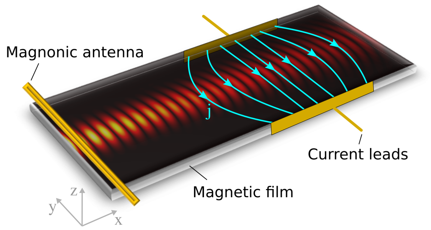
A similar nonreciprocal term in the dispersion relation can also be induced by an electric field 17 or by the antisymmetric exchange interaction, also known as Dzyaloshinskii-Moriya interaction (DMI) 18. Analogously to the Doppler shift induced by the currents, a frequency shift has been measured in ferromagnetic materials possessing DMI 19. For heterochiral ferromagnets (i.e., with spatially varying DMI), the reciprocal term causes a nontrivial refraction of spin waves at interfaces between regions with different DMI, as described by a generalized Snell’s law in Ref. 20. In this regard, the equivalency in the dispersion relations of SWs in the presence of DMI and SP current suggests that a spatially varying current density (as illustrated in Fig. 1) can be used to manipulate the propagation of SWs.
In this Letter, we detail the effect of a SP current on controlling the propagation of spin-waves. We show that the Zhang-Li STT induced by in-plane current has analogous effect to DMI for confining and controlling the propagation direction of magnons in the linear regime. We proceed to derive a Snell’s law to describe the scattering of spin-waves between regions with different current densities, and validate it by advanced simulations including solving Poisson’s equation within the micromagnetic framework. Finally we present selected tailored examples to illustrate how strategically applied current can be employed to advance logic and neuromorphic computing devices based on spin-waves.
1 Results and discussion
1.1 Spin-wave dispersion under applied current
Within the micromagnetic framework, we describe the magnetization of a thin extended ferromagnetic film by considering the vector field with constant magnetization modulus and the normalized magnetization direction at each point of the film 111In this paper we use an arrow for 3D vector fields such as the magnetization and the effective magnetic field and bold variables for 2D dimensional vectors in the plane such as the position , the -vector, and the current .. The dynamics of the magnetization is governed by the Landau-Lifshitz-Gilbert (LLG) equation
| (1) |
where is the gyromagnetic ratio, the dimensionless damping factor, and the effective field, which can be derived from the free energy by taking the functional derivative with respect to the magnetization: .
We extend the LLG equation by adding the torque which includes the adiabatic and non-adiabatic STT terms derived by Zhang and Li 10:
| (2) |
where
| (3) |
Here, is the two-dimensional differential operator, is a dimensionless constant that represents the degree of non-adiabaticity, the elementary charge and the Bohr magneton. The polarization is a property of the ferromagnet and does not depend on the magnetization. Although has the units of velocity, we refer to it as current since it is proportional to the SP current density . The most prominent effect of the STT is best understood by assuming small dissipation terms ( and ). In that case it is easy to prove that the solution of the LLG equation is given by if is the solution in absence of the STT. Put differently, adding the STT shifts the solution with a velocity 21. For instance, due to the STT, relaxed local structures such as domain walls and skyrmions will move with a velocity when the current is switched on. Accordingly, a SW packet traveling in the film will gain an additional velocity equal to . This insight will help to obtain an intuitive understanding of the results presented in this paper in which we study the effect of a non-uniform static current on the propagation of SWs.
The dynamics of the magnetization depends strongly on the characteristics of the magnetic film, incorporated in the free energy functional. In this paper, we take into account the contribution of exchange interaction and Zeeman energy due to applied bias magnetic field:
| (4) |
with exchange stiffness and bias field .
The ground state magnetization is the ferromagnetic (field-polarized) state in which the magnetization is aligned with the bias field . To study small deviations from the ground state it is useful to construct the right-handed coordinate system with . The effective field in this coordinate system becomes
| (5) |
where and . Here and in the next section, we focus on first order deviations from the ground state and consider the SW solution as , and , where represents the SW amplitude; is the SW angular frequency; k is the wave vector, and represents the damping of the SW. Substituting that into the LLG equation [Eq. (1)], with STT term given by Eq. (2) and effective field from Eq. (5), yields the dispersion relation (see supplementary material 22)
| (6) |
and damping parameter
| (7) |
where we define the length scale . Note that the damping of the SW decreases if the wave vector is parallel to the electron flow . Consequently, the attenuation length of a spin wave can be increased by applying a current opposite to the propagation direction, as predicted earlier by Seo et al. 23.
Propagation direction.—The dispersion relation consists out of circular isofrequencies in -space, which are shifted away from the origin due to the current. The center of the circular isofrequency is given by
| (8) |
and the radius by
| (9) |
with the minimal frequency .
The propagation velocity v of a wave packet is given by the gradient of the frequency in -space:
| (10) |
where defines the propagation direction. The velocity of the wave packet can be separated as
| (11) |
where and denote the component parallel and perpendicular to the wave vector respectively. Notice that, in general, the propagation direction is not parallel to the wave vector k, and the SW can be deflected in the presence of applied current.
1.2 Generalized Snell’s law
Let us now examine the propagation of SWs when experiencing nonuniform current distributions. For simplicity, we start with the example of a SW propagating between two regions with different current densities j, i.e. and . It is well known that SWs reflect at material boundaries, where the momentum parallel to the interface should be conserved. In the case of SP current, the change in current density is equivalent to an interface, and the momentum perpendicular to , i.e., , with the vector tangent to the interface, should be conserved. In our simple example that corresponds to , where the indices 1 and 2 refer to the incident and refracted waves respectively. If the propagation direction is parallel to the k vector, the well-known Snell’s law applies: , with and the incident and refracted angles respectively. However, since in our case the dispersion relation is asymmetric, the Snell’s law has to be adjusted as follows
| (12) |
where the angles are taken with respect to (i.e., the direction normal to the interface). Similarly generalized Snell’s laws for the refraction of SWs at domain walls and heterochiral interfaces were derived in Refs. 24 and 20.
1.3 Micromagnetic simulations
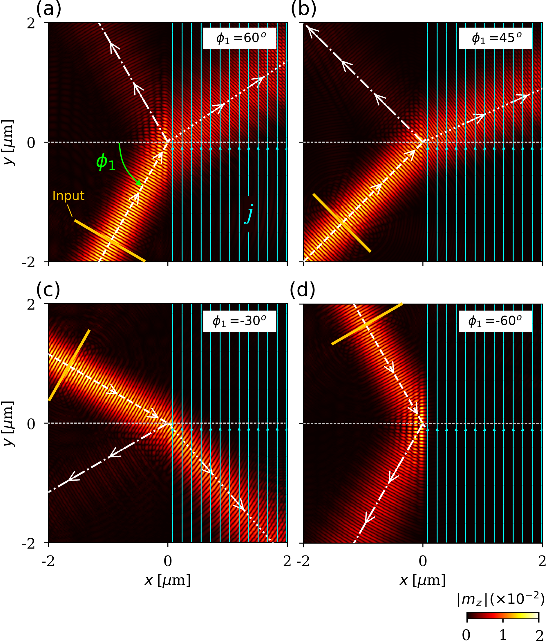
To realistically simulate a SW system in the presence of the SP current, we employ the micromagnetic framework and specifically its mumax3 implementation 25, 26 to calculate the SW refraction when propagating between two regions with different current densities.
The SW beams are created by a sinusoidal oscillating field applied in a narrow rectangular region (input antenna, see Fig. 2 (a)), where the field amplitude has a Gaussian profile in the transverse direction and is the oscillation frequency. For all simulations we consider , where T is the bias field applied along direction [see Methods section]. Fig. 2 (a-d) shows snapshots of the simulated SW propagation across the interface where the current density sharply changes, for different incident angles . White arrows denote the SW trajectories predicted by our Eq. (12), which are in excellent agreement with the micromagnetic simulations. Notice that the STT induced by the SP current can either deflect or confine the SWs. The critical incident angle above which the SW can not propagate for a given applied current, i.e., the SW undergoes total internal reflection, is obtained from our Snell’s law by imposing that the refracted wave is parallel to the interface (), as
| (13) |
Note that due to the asymmetric dispersion relation, the refraction is not symmetric for positive and negative incident angles. This is seen in the results for and in Fig. 2 (a,d), where only for the second case the total reflection of the SW is achieved.
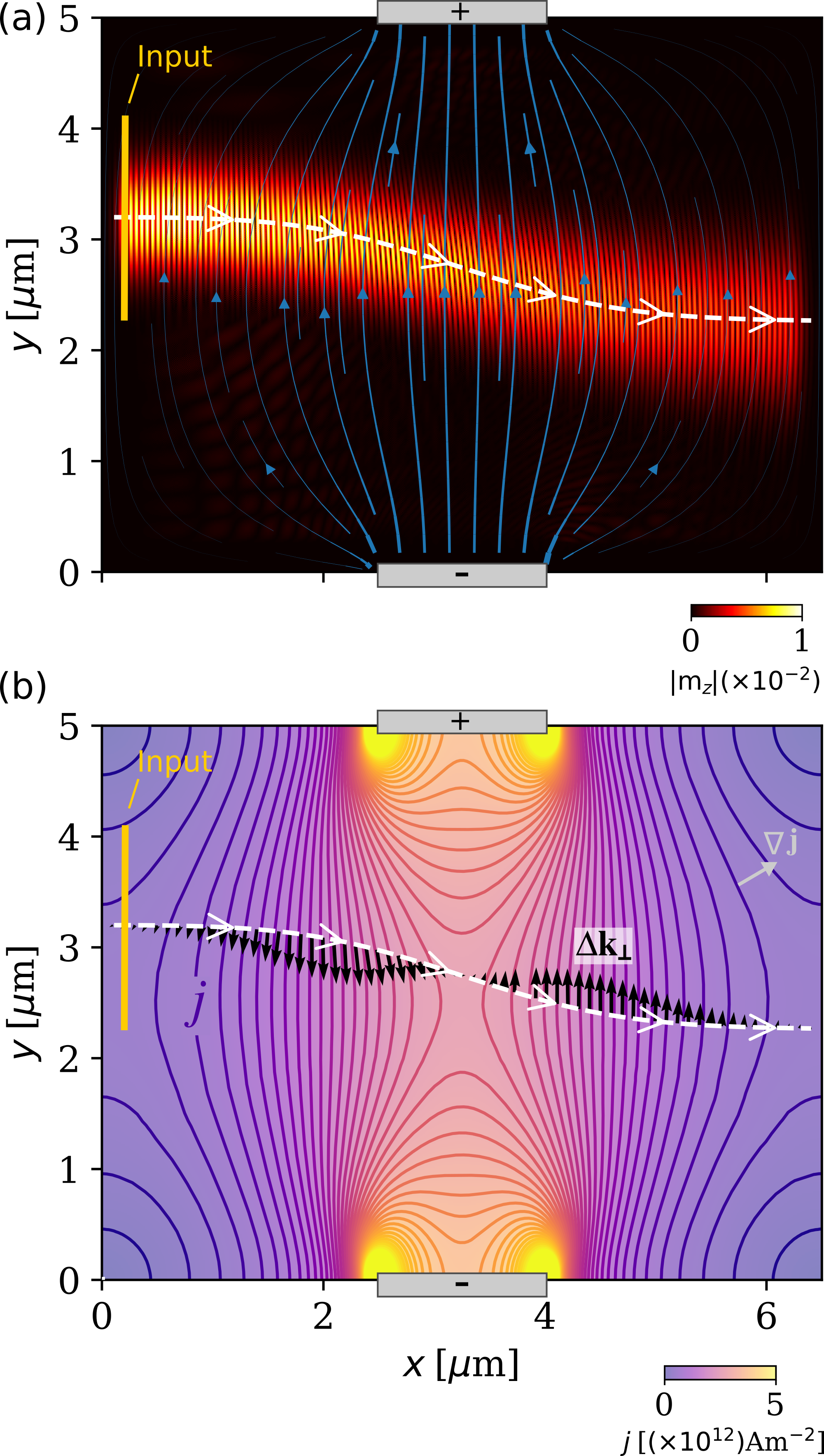
Poisson solver.—In practice, the current applied into the magnetic film will not exhibit a step-like distribution as considered in our previous example, but will spread continuously in the material obeying Poisson’s equation 27. To precisely calculate the interaction of SWs with such nonuniform current distributions, we implemented a Poisson solver in the micromagnetic simulation package mumax3 25. Fig. 3 (a) shows a snapshot of the simulated SW propagation across the nonuniform SP current density created between shown finite voltage contacts at the sample edges. Notice that the SW is pertinently deflected while crossing the region where current is applied, to finally reach a shifted propagation direction upon leaving the area pierced by current. Although both the direction and magnitude of the current continuously change as the SW propagates, our generalized Snell’s law still applies locally - the SW facing a local gradient in current density is effectively analogous to the earlier interface example. White arrows in Fig. 3 (a) indicate the SW trajectory calculated by iterating Eq. (12) as the SW propagates in the current distribution, where in each step the angle is taken with respect to the local . The predicted trajectory is in very good agreement with the simulation, demonstrating the general applicability of Eq. (12) even for nonuniform current distributions. Fig. 3 (b) shows the contour plot of the applied current density, where isolines can be seen as interfaces where the SW is refracted. quantifies the change in the propagation direction of the SW, shown as black arrows in Fig. 3 (b).
1.4 Multichannel SW selector
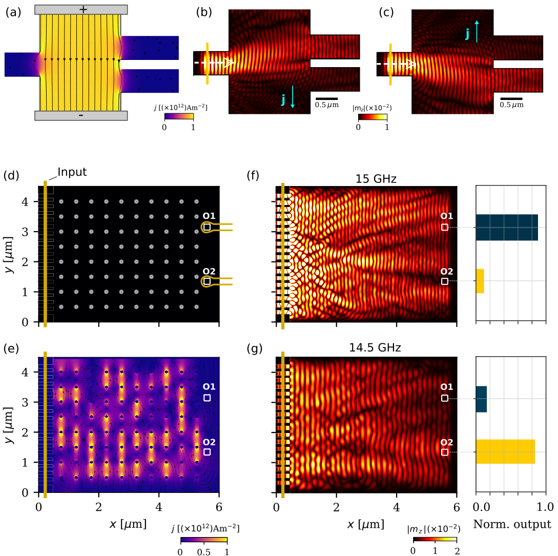
Performing logic operations with SWs generally requires combining different input waves that interfere with each other to generate a desired logic output state 5. The ability to guide SWs through nanochannels is therefore vital to the development of more complex SW-based circuitry. In this regard, SP currents can be used to precisely guide the SW in such devices, for example, to selectively “write” SWs in one of multiple nanotracks or logic gates in a larger microprocessor. We exemplify here such an application by simulating a multichannel SW selector, illustrated in Fig. 4 (a). The input SWs are generated in a channel on the left-hand side of the sample and propagate across a region where SP current is applied. By tuning the magnitude or direction of the applied current one can precisely deflect the SWs towards one of the output channels on the right side of the sample, as shown in Figs. 4 (b,c). Likewise, a frequency selector can be implemented considering the fact that SWs with different frequencies experience different deflections under the same applied current and can therefore be isolated into separate output channels.
1.5 Neuromorphic computing
Finally, we demonstrate the use of SP current for the design of neural-network hardware, based on SW propagation, where weights and interconnections of the network are realized by a pattern of the SP currents applied to the propagating substrate. Fig. 4 (d) illustrates the envisioned device. The input signal is created on the left and propagates across a region with a matrix of 80 voltage contacts [gray dots in Fig. 4 (d)] of 100 nm in diameter each. The read-out is taken from the two output antennas on the right side. An arbitrarily powered voltage matrix induces a distribution of the SP currents in the substrate that interacts with the input SWs. Training the neural network is equivalent to finding the current pattern that realizes the desired input-output mapping, for example, to classify different input signals by focusing them in different outputs. As suggested in Refs. 4 and 9, a back-propagation machine learning algorithm can be used for training a similar SW-based network, which can perform tasks such as vowel recognition and frequency classification. Here, we demonstrate that a simple Monte Carlo (MC) algorithm can perform the same task of training the neural network for simple classification problems. In our example, we perform a frequency-recognition operation, where we consider input SWs with frequencies and GHz. The neural network is trained to focus the SWs with 15 GHz to the output O and SWs with 14.5 GHz to the output O [see Figs. 4 (f,g)]. The voltage at each contact is randomly initialized in one of the three values: , or , with V, and a Metropolis algorithm is implemented by changing the voltage of one of the contacts at every MC step [see supplemental material 22]. The finally trained configuration [resulting in the current distribution shown in Fig. 4 (e)] is able to focus SWs of each frequency to the desired outputs as shown by the bar charts in Figs. 4 (f,g), and can therefore perform the classification operation. In the supplementary material, we show that the effects of Oersted and demagnetizing fields are negligible in our example 22. One should note however that the proposed neuromorphic application can be generalized for arbitrary scenarios, as long as all the relevant magnetic interactions are considered during the training process of the neural network. The here proposed fully electronic control enables facilitated reconfiguration of the neural network to perform different tasks within the same integrated circuit.
To identify the role of different material parameters in the current-induced SW scattering, and consequently in the proposed applications, let us consider the case of an SW propagating across two regions with different current densities, as in Fig. 2. In this scenario, for an incident angle and making use of Eqs. (12) and (3), the refraction angle of the SW is given by , where . Therefore, the current-induced SW scattering is maximized when is minimized. In other words, the SW scattering is maximized in materials with small exchange stiffness and for SWs with small wavenumber , as well as by increasing the SP current, represented by the polarization and applied current density . Moreover, it is worth mentioning here that applied current may locally increase the temperature of the system, and consequently affect the magnetic parameters such as the saturation magnetization , hence additional scattering may arise from such non-uniformity of the magnetic landscape in which SWs propagate. In Table 1 we show material properties of representative low-damping, metallic magnetic materials that can host spin waves and are therefore convenient candidates for the proposed control of SWs by SP current. As an additional example, we reproduced the neuromorphic application for the case of a Ni80Fe20 thin film in the supplementary material 22.
2 Conclusions
We have demonstrated the use of non-uniform spin-polarized current for the manipulation of spin-waves. We showed that the spin-transfer torque induced by the applied current has an effect analogous to DMI for confining spin-waves and controlling their propagation direction in the linear regime, and derived a generalized Snell’s law that describes the scattering of spin-waves between regions with different current densities. Finally, we implemented the calculation of the current distribution in micromagnetic simulations by solving the Poisson’s equation within the simulation package mumax3 (to be made available in the upcoming release of mumax4), in order to (i) validate the derived Snell’s law and (ii) demonstrate how strategically applied current distributions can be employed in magnonic logic and neuromorphic computing devices, thereby advancing the prospects of low-power spintronic hardware and artificial intelligence.
3 Methods
3.1 Micromagnetic simulations
For the simulations, we employ the micromagnetic framework MUMAX3 25, 26, where we consider nm thick magnetic films with saturation magnetization MAm-1, exchange stiffness pJm-1 30 and damping constant . The considered free energy density is given by Eq. (4), and the dynamics of the magnetization is governed by the LLG equation [Eq. (1)] with STT terms [Eq. (2)] accounting for in-plane applied currents. The in-plane bias field is set to , with T. For all simulations, we consider a system discretized into cells of size nm3. The polarization rate of the SP current is fixed at . The calculation of the current distribution is made by solving the Poisson’s equation for the considered geometries, where we assume the electrical conductivity as (m)-1.
This work was supported by the Research Foundation - Flanders (FWO-Vlaanderen, under Grant No. K226322N and 12A9223N), EoS ShapeME project, and Brazilian Agencies FACEPE, CAPES and CNPq.
Calculation of spin-wave dispersion relation under spin-polarized current; Monte Carlo training of neural network; Effect of Oersted and demagnetizing fields; Example of a spin-wave neural network in a Ni80Fe20 thin film.
References
- Christensen et al. 2022 Christensen, D. V.; Dittmann, R.; Linares-Barranco, B.; Sebastian, A.; Le Gallo, M.; Redaelli, A.; Slesazeck, S.; Mikolajick, T.; Spiga, S.; Menzel, S., et al. 2022 roadmap on neuromorphic computing and engineering. Neuromorphic Computing and Engineering 2022,
- Romera et al. 2018 Romera, M.; Talatchian, P.; Tsunegi, S.; Abreu A., F.; Cros, V.; Bortolotti, P.; Trastoy, J.; Yakushiji, K.; Fukushima, A.; Kubota, H., et al. Vowel recognition with four coupled spin-torque nano-oscillators. Nature 2018, 563, 230–234
- Shainline et al. 2017 Shainline, J. M.; Buckley, S. M.; Mirin, R. P.; Nam, S. W. Superconducting optoelectronic circuits for neuromorphic computing. Physical Review Applied 2017, 7, 034013
- Hughes et al. 2019 Hughes, T. W.; Williamson, I. A. D.; Minkov, M.; Fan, S. Wave physics as an analog recurrent neural network. Science advances 2019, 5, eaay6946
- Mahmoud et al. 2020 Mahmoud, A.; Ciubotaru, F.; Vanderveken, A. V., F.and Chumak; Hamdioui, S.; Adelmann, C.; Cotofana, S. Introduction to spin wave computing. Journal of Applied Physics 2020, 128, 161101
- Barman et al. 2021 Barman, A.; Gubbiotti, G.; Ladak, S.; Adeyeye, A. O.; Krawczyk, M.; Gräfe, J.; Adelmann, C.; Cotofana, S.; Naeemi, A.; Vasyuchka, V. I., et al. The 2021 magnonics roadmap. Journal of Physics: Condensed Matter 2021, 33, 413001
- Chumak et al. 2014 Chumak, A. V.; Serga, A. A.; Hillebrands, B. Magnon transistor for all-magnon data processing. Nature Communications 2014, 5, 1–8
- Chumak et al. 2015 Chumak, A. V.; Vasyuchka, V. I.; Serga, A. A.; Hillebrands, B. Magnon spintronics. Nature Physics 2015, 11, 453–461
- Papp et al. 2021 Papp, A.; Porod, W.; Csaba, G. Nanoscale neural network using non-linear spin-wave interference. Nature Communications 2021, 12, 1–8
- Zhang and Li 2004 Zhang, S.; Li, Z. Roles of Nonequilibrium Conduction Electrons on the Magnetization Dynamics of Ferromagnets. Physical Review Letters 2004, 93, 127204
- Ralph and Stiles 2008 Ralph, D. C.; Stiles, M. D. Spin transfer torques. Journal of Magnetism and Magnetic Materials 2008, 320, 1190–1216
- Wang et al. 2022 Wang, W.; Song, D.; Wei, W.; Nan, P.; Zhang, S.; Ge, B.; Tian, M.; Zang, J.; Du, H. Electrical manipulation of skyrmions in a chiral magnet. Nature Communications 2022, 13, 1–7
- Peng et al. 2021 Peng, L.; Karube, K.; Taguchi, Y.; Nagaosa, N.; Tokura, Y.; Yu, X. Dynamic transition of current-driven single-skyrmion motion in a room-temperature chiral-lattice magnet. Nature Communications 2021, 12, 1–7
- Bazaliy et al. 1997 Bazaliy, Y. B.; Jones, B. A.; Zhang, S.-C. Modification of the Landau-Lifshitz Equation in the Presence of a Spin-Polarized Current in CMR and GMR Materials. 1997, 57, 3213–3216
- Fernández-Rossier et al. 2004 Fernández-Rossier, J.; Braun, M.; Núñez, A. S.; MacDonald, A. H. Influence of a uniform current on collective magnetization dynamics in a ferromagnetic metal. Physical Review B 2004, 69, 174412
- Vlaminck and Bailleul 2008 Vlaminck, V.; Bailleul, M. Current-induced spin-wave doppler shift. Science 2008, 322, 410–413
- Mills and Dzyaloshinskii 2008 Mills, D. L.; Dzyaloshinskii, I. E. Influence of electric fields on spin waves in simple ferromagnets: Role of the flexoelectric interaction. Physical Review B - Condensed Matter and Materials Physics 2008, 78, 1–4
- Moon et al. 2013 Moon, S.-M., J.-H.and Seo; Lee, K.-J.; Kim, K.-W.; Ryu, J.; Lee, H.-W.; McMichael, R. D.; Stiles, M. D. Spin-wave propagation in the presence of interfacial Dzyaloshinskii-Moriya interaction. Physical Review B 2013, 88, 184404
- Cortés-Ortuño and Landeros 2013 Cortés-Ortuño, D.; Landeros, P. Influence of the Dzyaloshinskii–Moriya interaction on the spin-wave spectra of thin films. Journal of Physics: Condensed Matter 2013, 25, 156001
- Mulkers et al. 2018 Mulkers, J.; Van Waeyenberge, B.; Milošević, M. V. Tunable Snell’s law for spin waves in heterochiral magnetic films. Physical Review B 2018, 97, 104422
- Thiaville et al. 2005 Thiaville, A.; Nakatani, Y.; Miltat, J.; Suzuki, Y. Micromagnetic understanding of current-driven domain wall motion in patterned nanowires. Europhysics Letters 2005, 69, 990–996
- 22 See supplementary material at [url].
- Seo et al. 2009 Seo, S.-M.; Lee, K.-J.; Yang, H.; Ono, T. Current-induced control of spin-wave attenuation. Physical review letters 2009, 102, 147202
- Yu et al. 2016 Yu, W.; Lan, J.; Wu, R.; Xiao, J. Magnetic Snell’s law and spin-wave fiber with Dzyaloshinskii-Moriya interaction. Physical Review B 2016, 94, 140410
- Vansteenkiste et al. 2014 Vansteenkiste, A.; Leliaert, J.; Dvornik, M.; Helsen, M.; Garcia-Sanchez, F.; Van Waeyenberge, B. The design and verification of MuMax3. AIP Advances 2014, 4, 107133
- Leliaert et al. 2018 Leliaert, J.; Dvornik, M.; Mulkers, J.; De Clercq, J.; Milošević, M. V.; Van Waeyenberge, B. Fast micromagnetic simulations on GPU—recent advances made with. Journal of Physics D: Applied Physics 2018, 51, 123002
- Griffiths 2005 Griffiths, D. J. Introduction to electrodynamics. 2005
- Huang et al. 2008 Huang, S. X.; Chen, T. Y.; Chien, C. L. Spin polarization of amorphous CoFeB determined by point-contact Andreev reflection. Applied Physics Letters 2008, 92, 242509
- Conca et al. 2017 Conca, A.; Nakano, T.; Meyer, T.; Ando, Y.; Hillebrands, B. CoFeAlB alloy with low damping and low magnetization as a candidate for spin transfer torque switching. Journal of Applied Physics 2017, 122, 073902
- Papp et al. 2017 Papp, A.; Porod, W.; Csurgay, A. I.; Csaba, G. Nanoscale spectrum analyzer based on spin-wave interference. Scientific Reports 2017, 7, 1–9