Theory and experiments of spiral unpinning in the Belousov-Zhabotinsky reaction using a circularly polarized electric field
Abstract
We present the first experimental study of unpinning a spiral wave of excitation using a circularly polarized electric field. The experiments are conducted in the Belousov-Zhabotinsky(BZ) reaction, and the system is modeled using the Oregenator model. The mechanism of unpinning in the BZ reaction differs from that in the physiological medium. We show that the wave unpins when the electric force opposes the propagation of the spiral wave. We developed an analytical relation of the unpinning phase with the initial phase, the pacing ratio, and the field strength and verified the same.
The Belousov-Zhabotinsky (BZ) reaction has served as the prototype of a large class of systems that display excitation waves, including the waves of action potentials seen in the heart [1], brain [2], retina [3], and waves of communication in the social amoeba dictyostelium discoideum [4, 5]. Excitation waves in these systems exhibit strikingly similar spatio-temporal patterns such as expanding target waves or rotating spiral waves [6, 7, 8]. Recently there has been a renewed interest in the pattern formation in the BZ reaction because of the active nature of the chemical waves: their wavefronts are electrically charged [9, 10] and resultant changes in the surface tension on the droplets of BZ reagents in an oily medium can propel the droplets [11, 12].
A characteristic feature of excitation waves is their tendency to pin to heterogeneities in the medium [13, 14, 15, 16]. A pinned rotating wave requires a carefully administered stimulus to remove it from the heterogeneity [17]. This is especially pertinent in cardiac tissue since stable pinned rotating waves can be life-threatening [18, 17].
Several groups have proposed methods for controlling such pinned waves using either pulsed electric field [1, 19] or, more recently, circularly polarized electric field [20, 21, 22]. Numerical studies have shown that circularly polarized electric fields (CPEF) are more efficient in controlling cardiac excitation waves [22, 23, 20]. In particular, CPEF requires less energy and is more efficient in controlling pinned rotating waves [20, 21]. Our systematic investigations on the mechanism of CPEF indicated that the spiral wave could be unpinned if the frequency of the CPEF is more than a cut-off frequency [23].
It is observed that chemical waves are also prone to pinning [13], and they can also be unpinned using electric field [9, 24]. However, there is an essential distinction between the chemical wave and the waves in physiological tissue. In the latter, the electric force does not affect the excitation wave directly, instead, they unpin by inducing secondary excitations from the heterogeneities [25]. In the chemical medium, on the other hand, the wavefront contains charged ions such as and , which can be moved by the applied electric field, , i.e., the electric field in a chemical medium exerts an advective force directly on the wavefront [9, 26, 27]. Such an electric force on the wave is not reported in the physiological tissue. It is also observed that the chemical wave unpins as it moves away from the anode, and not when moving towards it [9].
So far, there have not been any experimental reports of unpinning spiral waves using CPEF, either in the chemical medium or the cardiac tissue. However, CPEF is realized in BZ medium to control spiral turbulence [28]. In this paper, we report the first experimental studies of spiral wave unpinning using CPEF in an excitable medium. However, the mechanism of how CPEF acts on a chemical wave is different from that of the cardiac excitation wave. In particular, we find no cut-off frequency for CPEF to unpin a chemical wave. We vary the pacing ratio, initial spiral phase, and field strength. We deduced that the wave unpins when the component of the electric field vector along the direction of the spiral equals or exceeds a critical field strength. Based on this, we predict the unpinning angle as a function of the initial position of the spiral wave, the frequency, and the strength of the electric field. We show that our analytical formulation agrees with experimental data and numerical results.
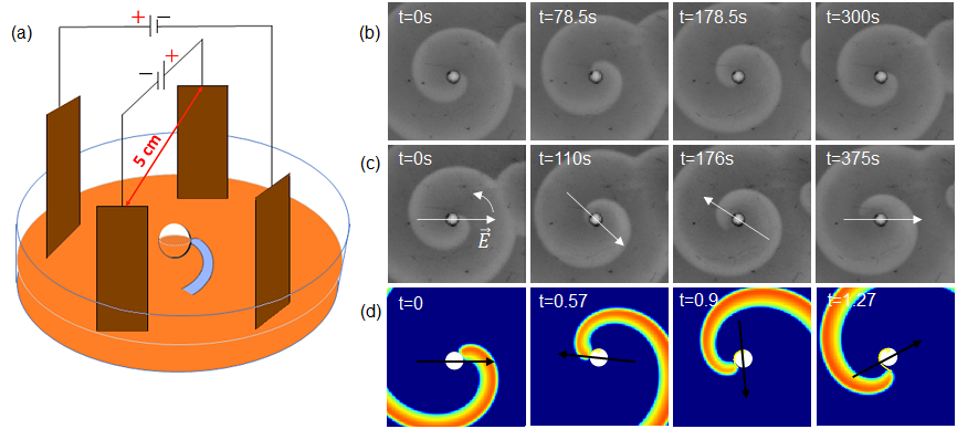
In this paper, we focus on the unpinning of an anti-clockwise (ACW) rotating spiral using a CPEF rotating in the same direction. We conducted our studies in the ferroin-catalyzed BZ reaction in a petri-dish, as described in detail in Ref. [9]. Briefly, we start with the following initial reagents: [] = 0.16 M, [] = 40 mM, [Malonic acid] = 40 mM, and [Ferroin] = 0.5 mM. The reaction mixture is embedded in 1.4 w/v of agar gel to avoid any hydrodynamic perturbations. The single reaction layer of thickness m is taken in a glass petri dish of diameter m. A circular excitation wave is created at the center of the reaction medium by inserting a silver wire. By disrupting the motion of the circular wavefront, a pair of counter-rotating spirals are created. To generate a pinned spiral wave, a glass bead of diameter mm is carefully placed at the tip of one of the spirals. The pinning of the spiral tip to the obstacle is confirmed after 1-2 rotations. An anticlockwise circularly polarized electric field (CPEF) is applied using two pairs of copper electrodes as in Fig. 1(a). Images of the reaction medium are recorded using a CCD camera at every interval for hours.
To model this experiment, we use a two-dimensional Oregonator model. The model equations are given by
| (1) |
| (2) |
Here, is the activator variable, and is the inhibitor variable (corresponding to the rescaled concentrations of [HBrO2] and the catalyst, respectively). is the circularly polarized electric field. The electric field is added as an advection term for the variables and . An obstacle is added to this domain by setting the diffusion coefficient of the activator to a very low value. Details of the model and the simulations are given in Ref. [9].
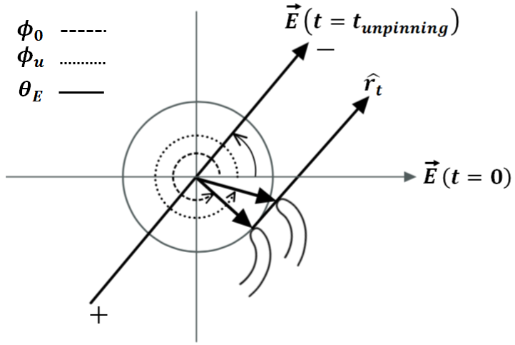
The rotating chemical wave in the BZ reaction medium can get anchored into the boundary of the glass bead and form a very stable pinned wave, as shown in Fig. 1(b). A similar situation occurs in the numerical simulation of the model equations, where the spiral wave can get anchored to the obstacle in the domain. It is known that this wave can be unpinned with an electric field [9, 24]. Here we employ the circularly polarized electric field (CPEF) using two cross-electrodes (see Fig 1.(a)). The CPEF can unpin the wave if the amplitude of the electric field equals or exceeds a certain threshold value (), as shown in Fig. 1(c). An arrow indicates the instantaneous direction of the electric field. Similar unpinning is also seen in the simulations [Fig. 1(d)]. To understand the unpinning process, we measure the location at which the wave unpins from the obstacle. We can quantify the spiral location by the phase of the spiral tip on the obstacle boundary. The phase is the angle of the spiral tip, measured in degrees from the -axis along the anticlockwise direction with the obstacle center as the origin. The phase of the spiral when we start the CPEF is denoted by and the phase when the spiral unpins from the boundary is denoted by [Fig. 2]. The instantaneous direction of the electric field is denoted by the angle . The direction of the spiral is along the tangent at the obstacle, and this direction is denoted by . We define the pacing ratio, , as the ratio of the frequency of the CPEF () to that of the spiral (), i.e., . We have varied from 0.25 to 3.
Our observations can be summarised as follows: (1) The chemical wave can be unpinned with CPEF for all pacing ratios (between 0.25 to 3), provided the strength of the electric field is equal or above a threshold.
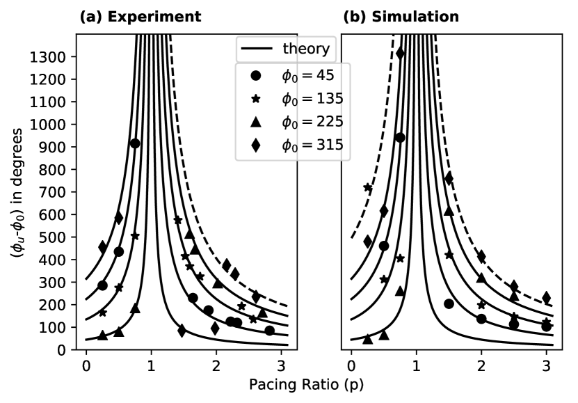
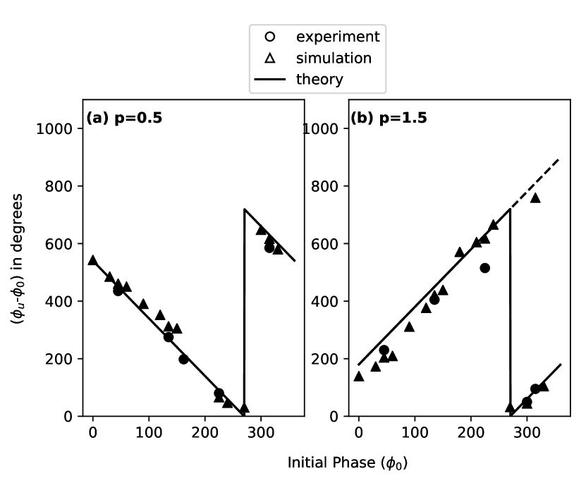
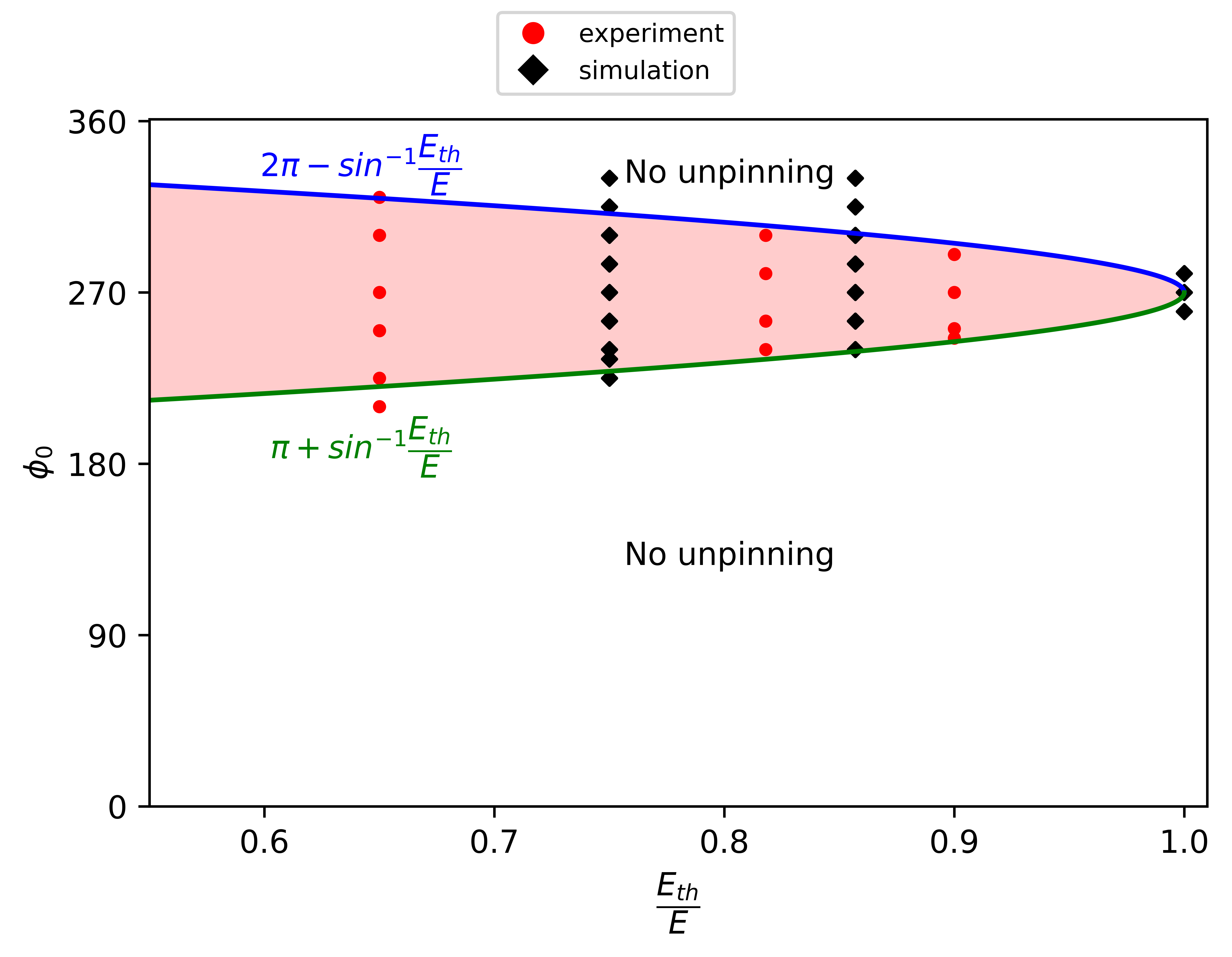
There is no cut-off frequency and both overdrive pacing () and underdrive pacing () are equally effective. (2) The spiral unpinning phase varies linearly with . It increases for overdrive pacing and decreases for underdrive pacing (Fig. 4). (3) (- ) varies with the pacing ratio, , as in Fig. 3. (4) Unpinning is not guaranteed within one rotation of the spiral. In a few cases, where either the relative rotation of the spiral-field pair varies quickly (extremely overdrive or underdrive pacing), or lies close to the expected (i.e., ( - 0), the spiral misses unpinning at the first expected phase. Here, the unpinning may happen later at a phase where the unpinning condition is satisfied again (dashed lines in Fig. 3). (5) It takes several rotations for the chemical wave to unpin as approaches 1 (when the spiral and the CPEF are rotating with the same frequency). For resonant pacing (), the wave cannot be unpinned except for a small range of initial conditions (). This range increases with the strength of the electric field (Fig. 5).
These results can be analyzed in light of our recent work with the DC electric fields [9]. We found that the electric field exerts a retarding force on the chemical wavefront, which is maximum when the field direction is along the direction of the wavefront. For a CPEF with field strength this condition is satisfied when . From this, we can estimate the unpinning angle as,
| (3) | |||||
| (4) |
When , the wave can be unpinned only when . The theoretical solid curves in Figs. 4 and 3 are based on the above equation.
For a field strength greater than , the wave must unpin when the component of along reaches the critical threshold, i.e., . This condition gives an upper-bound and lower-bound for possible spiral unpinning phases .
For overdrive pacing with , the unpinning phase window is given by
| (5) |
with a width . In most of the cases, the unpinning condition (Eq. 5) is satisfied at the lower bound of this range. However, unpinning is possible at any point inside the window (refer Fig.1 in the supplementary material).
For underdrive pacing i.e, for , the unpinning phase window is
| (6) |
The width of this window is . Depending on the strength of the electric field, the width of the window increases. The window reduces to a point when .
For p = 1, unpinning happens only if the following condition is satisfied.
| (7) |
Thus for the range of initial phases that lead to unpinning increases with the field strength, . Figure. 5(a) shows the initial spiral phases that lead to successful unpinning as a function of .
In summary, we have presented the first experimental studies using a circularly polarized electric field to unpin an excitation wave. We observed unpinning with overdrive, underdrive and resonant pacing. Because of the charge on the chemical wavefront, the mechanism of chemical wave unpinning differs from that in other excitable media. The wave unpins when the electric field component along the tangential direction of spiral propagation is equal or more than the critical threshold; i.e., when the electric force opposite to the instantaneous spiral propagation is above the threshold value. Based on this condition, we are able to predict the unpinning phase, and the same has been verified in simulations and in experiments.
The unpinning of a rotating chemical wave presents a unique physical situation. In our studies, the unpinning happens when the anode ‘catches’ the spiral from behind while chasing it. If it fails to halt the wave and overtakes it, it has to come back again to act on it. i.e., the wave can only be unpinned while propagating away from the anode. A similar kind of asymmetry in the chemical wave behavior in an external electric field has been observed in previous studies. The speed of chemical wave propagation decreases as it propagates towards the anode and it decreases as it rotates away from it. Depending on the velocity, the size of a free spiral core varies; as the spiral accelerates, the core-size decreases, and as it decelerates the core-size increases [27]. As a result, a drift of the spiral tip occurs in the medium. The drift occurs with a parallel component which is always directed towards the anode and a chirality-dependent perpendicular component [29]. The phenomenon of spiral drift is addressed in numerous experimental and computational studies with dc, ac, and polarized electric fields [29, 30, 31]. Most of the important field effects in the BZ reaction could be explained with the electromigration of and ions. Only a few studies investigated the effect of an electric field on a pinned spiral wave in the BZ reaction. In a unidirectional field, the spiral always unpins as it rotates away from the anode [24, 9]. In light of previous results, we can assume that the wave can only be unpinned when it is retarded by the electric field, and not when it is accelerated by it. During retardation, the core size increases, and the spiral can only pin weakly to obstacles smaller than the spiral core [14, 32]. This could be the reason for the asymmetric nature of the unpinning. As a prototype model, the BZ reaction is expected to show all the qualitative features observed in other excitable systems. On the contrary, our studies show that the chemical excitation waves interact uniquely with an external electric field.
Acknowledgements.
We thank Beneesh P B, Deepu Vijayasenan, Ajith K M, K V Gangadharan, and Muhammed Mansoor C B for discussions. Experiments were conducted using a grant (ECR/2016/000983) from Science and Engineering Research Board, Department of Science and Technology (SERB-DST), India.Author Contributions
S.V.A and T.K.S conceived the study. S.V.A performed the experiments, and P.S. built the experimental setup. S.P and A.S performed numerical simulations. S.V.A, A.S, and T.K.S analysed the data. A.S and T.K.S developed the theory. S.V.A and T.K.S wrote the paper. All authors helped to edit the paper.
References
- Luther et al. [2011] S. Luther, F. H. Fenton, B. G. Kornreich, A. Squires, P. Bittihn, D. Hornung, M. Zabel, J. Flanders, A. Gladuli, L. Campoy, and et al., Nature 475, 235 (2011).
- Huang et al. [2004] X. Huang, W. C. Troy, Q. Yang, H. Ma, C. R. Laing, S. J. Schiff, and J.-Y. Wu, J. Neurosci. 24, 9897 (2004).
- Yu et al. [2012] Y. Yu, L. M. Santos, L. A. Mattiace, M. L. Costa, L. i. C. Ferreira, K. Benabou, A. H. Kim, J. Abrahams, M. V. Bennett, and R. Rozental, Proc. Natl. Acad. Sci. U.S.A. 109, 2585 (2012).
- Noorbakhsh et al. [2015] J. Noorbakhsh, D. J. Schwab, A. E. Sgro, T. Gregor, and P. Mehta, Phys. Rev. E 91, 062711 (2015).
- Kamino et al. [2017] K. Kamino, Y. Kondo, A. Nakajima, M. Honda-Kitahara, K. Kaneko, and S. Sawai, Proc. Natl. Acad. Sci. U.S.A. 114, E4149 (2017).
- Zhang et al. [2019] Y. Zhang, F. Wu, C. Wang, and J. Ma, Phys. A: Stat. Mech. Appl. 521, 519 (2019).
- Zykov [2018] V. S. Zykov, Philos. Trans. Royal Soc. A 376, 20170379 (2018).
- Sinha and Sridhar [2014] S. Sinha and S. Sridhar, Patterns in excitable media: Genesis, dynamics, and control (CRC Press, 2014).
- Amrutha et al. [2022] S. V. Amrutha, A. Sebastian, P. Sibeesh, S. Punacha, and T. K. Shajahan, J. Phys. Chem. C 10.1021/acs.jpcc.2c01452 (2022).
- Steinbock et al. [1992] O. Steinbock, J. Schütze, and S. Müller, Phys. Rev. Lett. 68, 248 (1992).
- Jin et al. [2017] C. Jin, C. Krüger, and C. C. Maass, Proc. Natl. Acad. Sci. U.S.A. 114, 5089 (2017).
- Ryabchun et al. [2022] A. Ryabchun, D. Babu, J. Movilli, R. Plamont, M. C. Stuart, and N. Katsonis, Chem 8, 2290 (2022).
- Sutthiopad et al. [2015] M. Sutthiopad, J. Luengviriya, P. Porjai, M. Phantu, J. Kanchanawarin, S. C. Müller, and C. Luengviriya, Phys. Rev. E 91, 052912 (2015).
- Lim et al. [2006] Z. Y. Lim, B. Maskara, F. Aguel, R. Emokpae Jr, and L. Tung, Circulation 114, 2113 (2006).
- Zemlin and Pertsov [2012] C. W. Zemlin and A. M. Pertsov, Phys. Rev. Lett. 109, 038303 (2012).
- Shajahan et al. [2007] T. K. Shajahan, S. Sinha, and R. Pandit, Phys. Rev. E 75, 11929 (2007).
- Bittihn et al. [2010] P. Bittihn, A. Squires, G. Luther, E. Bodenschatz, V. I. Krinsky, U. Parlitz, and S. Luther, Philos. Trans. A. Math. Phys. Eng. Sci. 368, 2221 (2010).
- Gray and Wikswo [2011] R. Gray and J. Wikswo, Nature 475, 181 (2011).
- Punacha et al. [2019] S. Punacha, S. Berg, A. Sebastian, V. I. Krinski, S. Luther, and T. Shajahan, Proc. R. Soc. A 475, 20190420 (2019).
- Feng et al. [2014] X. Feng, X. Gao, D.-B. Pan, B.-W. Li, and H. Zhang, Sci. Rep. 4, 4831 (2014).
- Pan et al. [2016] D.-B. Pan, X. Gao, X. Feng, J.-T. Pan, and H. Zhang, Sci. Rep. 6, 1 (2016).
- Feng et al. [2022] X. Feng, X. Yin, J. Wen, H. Wu, and X. Gao, Chaos 32, 093145 (2022).
- Punacha et al. [2020] S. Punacha, A. N K, and T. K. Shajahan, Phys. Rev. E 102, 032411 (2020).
- Sutthiopad et al. [2014] M. Sutthiopad, J. Luengviriya, P. Porjai, B. Tomapatanaget, S. C. Müller, and C. Luengviriya, Phys. Rev. E 89, 052902 (2014).
- Pumir et al. [2007] A. Pumir, V. Nikolski, M. Hörning, A. Isomura, K. Agladze, K. Yoshikawa, R. Gilmour, E. Bodenschatz, and V. Krinsky, Phys. Rev. Lett. 99, 208101 (2007).
- Jiménez et al. [2013] Z. A. Jiménez, Z. Zhang, and O. Steinbock, Phys. Rev. E 88, 052918 (2013).
- Agladze and De Kepper [1992] K. Agladze and P. De Kepper, J. Phys. Chem. 96, 5239 (1992).
- Ji et al. [2013] L. Ji, Y. Zhou, Q. Li, C. Qiao, and Q. Ouyang, Phys. Rev. E 88, 042919 (2013).
- Schmidt and Müller [1997] B. Schmidt and S. C. Müller, Phys. Rev. E 55, 4390 (1997).
- Chen et al. [2006] J.-X. Chen, H. Zhang, and Y.-Q. Li, J. Chem. Phys. 124, 014505 (2006).
- Li et al. [2017] T.-C. Li, X. Gao, F.-F. Zheng, D.-B. Pan, B. Zheng, and H. Zhang, Sci. Rep. 7, 1 (2017).
- Pumir et al. [2010] A. Pumir, S. Sinha, S. Sridhar, M. Argentina, M. Hörning, S. Filippi, C. Cherubini, S. Luther, and V. Krinsky, Phys. Rev. E 81, 010901 (2010).