Calibration of the ICARUS cryogenic photo-detection system at FNAL
Abstract
The calibration of the ICARUS photo-detection system is based on a low power laser diode at 405 nm. Laser pulses arrive to one optical switch and then are sent to 36 UHV flanges, by 20 meters long optical patches. Light is then delivered to the ten PMTs connected to a single flange, by 7m long injection optical patches. Extensive tests of the used components and care in the design of the optical system have guaranteed to each PMT a sizeable calibration signal with minimal distortion, with respect to the original one. Gain equalization of PMTs has reached a 1 resolution. In this procedure data from background photons were also used. The distribution of the PMTs’ signal arrival time has a distribution with a resolution less than 1 ns, thus allowing a good determination of the absolute event timing. The status of the laser calibration system with its possible upgrades will be reported.
keywords:
Laser diodes , PMTs , calibration1 Introduction
ICARUS T600 [1] is presently used as far detector of the Short Baseline Neutrino (SBN) program at Fermilab (USA) to search for a possible LSND-like sterile neutrino signal at O(eV2 ) [2]. It is made of two identical cryostats, filled with about 760 tons of ultra-pure liquid Argon. Each cryostat houses two TPCs with 1.5 m maximum drift path, sharing a common central cathode. Charged particles interacting in liquid argon produce both scintillation light at 128 nm and ionization electrons. ICARUS is placed at shallow depth on the Booster Neutrino beam (BNB). To reduce the cosmic ray background, in addition to a full coverage cosmic ray tagger (CRT), a system based on 360 large area Hamamatsu R5912-MOD photomultipliers (PMTs) [3], directly immersed in liquid Argon, is used to detect scintillation light. To exploit the BNB bunch structure, for futher rejection of out-of-bunch cosmic events, an overall time resolution ns is needed. This and the trigger system require an accurate calibration in gain and time of each PMT.
2 The laser calibration system
The PMTs equalization may be performed by using fast laser pulses, as done in previous experiments such as Borexino at LNGS [4] and HARP at CERN PS [5]. The light pulse from a PLP10 Hamamatsu laser diode is sent to each PMT via a distribution system including an Arden Photonics Mode Scrambler (MS), a DD-100 OZ/Optics programmable attenuator(ATT), a 10 m armed fiber patch cable, followed by one 1x46 Agiltron optical switch (where 10 channels are spares). From this 20 m fiber patch cords go to VACOM UHV optical feedthroughs (36) on CF40 flanges, mounted on CF40-CF20 nibbles, as shown in figure 1 . Inside the T600 tank, 1x10 Lightel fused fiber splitters attached to each nibble deliver the input laser signal to the window of each PMT. While an optical switch delivers the laser signal to a single output channel, a 1xN optical switch distributes the input signal among N output channels. The light delivery system must have a minimal spread in channel-to-channel total delay () and delivered signal power in front of each PMT.
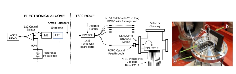
In addition laser pulses have to be delivered to the PMT’s photocathode with a minimal attenuation and without a deterioration of the original timing characteristics.
3 Optical components characterization
To keep costs low, commercial optical components (fibers, optical switches, fused optical splitters, …) were used. As these components are easily available only at Telecom wavelengths ( nm), we had to characterize their behaviour at 400 nm with a dedicated test bench at INFN Milano Bicocca. To minimize alignment problems multimode fibers (MM) instead of single mode ones (SM) were used. At this point, the remaining main task was to found a suitable optical switch and fused 1x10 optical splitters with channel-to-channel minimal spread in insertion losses (IL) and delay. The choice was to use an Agiltron 1x46 optical switch and Lightel 1x10 fused optical splitters. In the optical switch, the FWHM of the laser pulses is increased at most by and the insertion loss (IL) is less than 0.5 dB, with a cross talk dB. Channel-to-channel output uniformity is better than and the RMS of internal time delays is 10 ps. Instead, a typical splitter increases laser pulse FWHM of less than and has an IL less than 3 dB. For each splitter, the signal uniformity in the 10 output channels is less than aside one leading channel, by construction, that has to be attenuated. Average internal delays of the 36 splitters are within 80 ps (aside two, belonging to a different batch).
UHV optical feedthroughs convey the laser pulse inside the Icarus cryogenic tank. The adopted solution from VACOM, with a MM 50 m core fiber, had a measured transmission around 80 %, introduced an additional delay ps and a negligible additional time dispersion (FWHM). To adapt these flanges to the existing T600 chimneys CF40-CF200 nibbles are used, see figure 1 for details. As the splitters have to work, inside the T600 chimneys, at a slightly lower temperature than the T600 roof and the 7m injection patches at cryogenic temperatures, inside the LAr bath, tests were done to assess their dependence from temperature, using a Lauda thermal machine (precision 0C) in the range C and with bath inside a dewar, see reference [6].
4 System performances
At the PMTs’ front face, a total delay of the laser signal ( ns) with a channel-to-channel spread estimated at less than 200 ps was measured both in situ and in laboratory. Up to the UHV flanges a dB optical signal attenuation was measured. The attenuation of the 7 m injection patches was measured as dB for the full 410 sample (best 360 used).
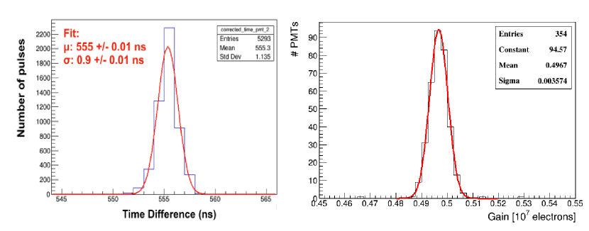
For calibration purposes, charge spectra from PMTs were recorded integrating laser signals over a 100 ns window. For each PMT data were taken at different voltages to allow the determination of the gain vs voltage curve and thus provide the voltage needed for a nominal gain set at . A fine tuning with background single photoelectrons is then applied to reduce the relative gain spread to less than , as shown in figure 2. In the same figure the distribution of the time difference between the trigger and the PMT signal is shown. Timing of PMTs signals is given by , where the trigger pulse is synchronized with the beam RF. Laser pulses permit the monitoring of possible variation of along the data taking and between different channels. With the obtained resolution of 1 ns, it is possible to determine the absolute timing of collected events, for trigger and cosmic rays rejection purposes.
As the PMTs’ response to calibration pulses is sizeable, as measured in situ using the optical attenuator, the replacement of the optical switch (10 PMTs calibrated in a single run) with a custom 1x36 optical splitter (360 PMTs calibrated in the same run) is foreseen in the next future. This will allow a much faster laser calibration procedure.
5 Conclusions
The light detection system of ICARUS T600 is fully operational allowing a regular data taking. Calibration of the PMTs’ gain has a spread less then while PMTs timing has a resolution better than 1 ns. Some upgrades are foreseen to improve the automation and reduce the time needed for the laser calibration procedures.
Acknowledgements
This work was supported by EU Horizon 2020 grant Agreements n. 74303, 822185, 858189 and 101003460.
References
- [1] M. Bonesini, A. Menegolli, PoS (EPS-HEP2019) (2019).
- [2] R. Acciarri, et al., arxiv.org/abs/arXiv:1503.01520.
- [3] B. Ali-Mohammadzadeh, et al., JINST 15 (10) (2020) T10007.
- [4] B. Caccianiga, et al., Nucl. Instr. Meth A496 (2003) 353.
- [5] M. Bonesini, et al., IEEE Trans. Nucl. Phys. 50 (4) (2003).
- [6] M. Bonesini, et al., JINST 15 (05) (2020) C05042.