360° Stereo Image Composition with Depth Adaption
Abstract.
360° images and videos have become an economic and popular way to provide VR experiences using real-world content. However, the manipulation of the stereo panoramic content remains less explored. In this paper, we focus on the 360° image composition problem, and develop a solution that can take an object from a stereo image pair and insert it at a given 3D position in a target stereo panorama, with well-preserved geometry information. Our method uses recovered 3D point clouds to guide the composited image generation. More specifically, we observe that using only a one-off operation to insert objects into equirectangular images will never produce satisfactory depth perception and generates ghost artifacts when users are watching the result from different view directions. Therefore, we propose a novel view-dependent projection method that segments the object in 3D spherical space and projects each part to a stereo camera pair facing in that direction. The individually projected results are then fused to remove any gaps or overlaying artifacts between parts. A user study demonstrates that our method can provide good depth perception and removes ghost artifacts. The view-dependent solution is a potential paradigm for other content manipulation methods for 360° images and videos.
1. Introduction
Advances in virtual reality (VR) and digital media technology have allowed people to virtually teleport to a virtual environment. This immersive experience provides tremendous opportunities in entertainment, education, and enriched experiences not directly accessible owing to safety or cost (laga2020survey). An economical way to construct such a virtual scene is to capture omnidirectional stereo images or videos from the real world. Therefore, there have been emerging research interests in 360° image and video processing for better immersive experiences in VR applications. But the question of how to manipulate the content of 360° stereo images remains less investigated. As a fundamental task in content manipulation, seamless image composition and cloning have been well-studied in the computer graphics and vision communities, especially for 2D images and videos (Jue_2007; farbman2009coordinates; luo2012perspective; dai2021learning). However, as demonstrated in the most recent 360° image/video processing work, such as stabilization (tang2019joint), depth estimation (wang2020360sd), optical flow estimation (li2022deep), and edit propagation (zhang2021efficient; zhang2022fast), the methods designed for normal 2D images cannot be easily extended to work for 360° images, because of their incorrect spatial relationship measurement in the spherical domain.
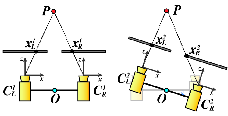
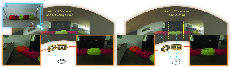
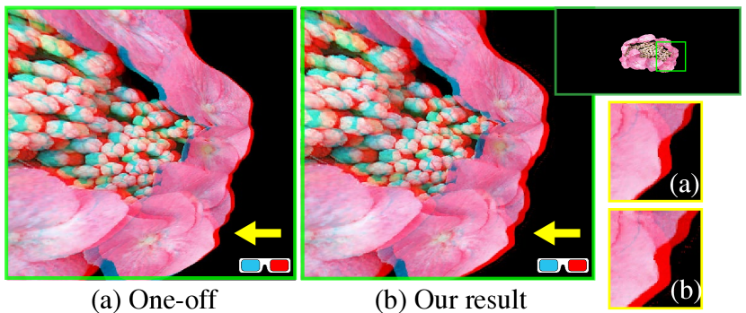
Besides the typical problems that any image composition method has to cope with, such as gradient mismatch and complex object boundaries, there is an additional challenge with 360° stereo images: the consistency of the depth perception when the user is focusing on any part of the composited result. That issue can be neglected in planar stereo image composition (tong2012stereopasting) where a pair of camera positions are defined to look at the scene center, since the field-of-view (FoV) is limited in 2D images. However, 360° stereo images allow users to rotate their view directions to focus on an arbitrary region of the scene. The 360° images/videos are pre-loaded for the left and right eyes and played by directly projecting the left/right panorama to the left/right viewport for efficiency. If the stereo composition is only conducted as a one-off operation for a predefined user position, i.e., directly pasting the source regions from the left-view and right-view to the stereo equirectangular images for the final result, the perceived depths will not be correct unless the user’s view direction is the same as the predefined cameras. Fig. 2 demonstrates the issue: When a user rotates their head with a VR headset, the depths of scene points vary, so the fixed disparity of a stereo pixel pair generated by the one-off composition can never satisfy all the possible view directions.
In this paper, we propose a novel method to insert stereo objects into a target 360° stereo image with a convincing appearance and well-preserved depth information when viewers change their viewing orientation. Our method uses the estimated depth information of both source and target stereo images to guide the generation of the stereo pair of inserted objects, ensuring the correct geometry when watching the object inserted at an arbitrary 3D position. For addressing the aforementioned depth inconsistency issue, we propose a solution where the generated disparities of stereo pixel pairs can fit different view directions of the virtual view pair. Instead of using a single pair of camera positions when generating the left and right panoramas, our camera model uses multiple pairs of camera positions facing in different directions. For different parts of the object, we separately generate the stereo content using the pairs of cameras looking in each direction and then merge the content of all the parts in the final left/right panoramas. More particularly, we build a deep neural network to learn to generate dense depth maps and object masks to produce high-quality stereo content when the object pose changes in the composited results, outperforming all the previous stereo image composition methods. In our user study, we find that our method offers the best depth perception, especially when the inserted object covers a large FoV in the final result.
Our contributions are as follows:
-
•
An omnidirectional stereo image composition algorithm, which can composite a stereo object into a 360° panoramic background for VR applications. Our method has good fidelity, ensuring the fundamental 3D geometries of the inserted objects by guiding the content manipulation in 3D space.
-
•
A novel solution to address the depth perception issue in stereo panorama content generation. We use a camera model that is more suitable to the geometry of stereo panoramas than a model that assumes projection onto a single plane.
-
•
A deep model that is able to synthesize dense and accurate depth maps and object masks to facilitate stereo image generation for different object poses.
2. Related Work
Our work involves efficient compositing of 3D objects into stereoscopic 360° panoramas. We briefly cover the key related work in image manipulation, 360° image processing, stereoscopic editing, and 3D object manipulation.
2.1. Image Matting, Composition, and Segmentation
Image composition is a basic operation for content manipulation, used initially for film and video production (fielding1965technique). Early methods focused on providing intelligent scissors for object segmentation to composite (mortensen1995intelligent; mortensen1998interactive). In recent decades, alpha matting (Jue_2007) and gradient-domain methods (perez2003poisson) have become mainstream approaches for composition. Matting allows us to extract accurate boundaries with transparency values of foreground pixels for realistic object insertion (smith1996blue; chuang2001bayesian). Gradient-domain methods, such as Poisson Blending (perez2003poisson), help find a smooth transition between the background and the inserted foreground. Previous work also focused on various aspects of image blending, such as the environment lighting effects (zongker1999environment; wenger2005performance; unger2003capturing). More recently, deep learning-based approaches have been proposed to increase the accuracy of the extracted soft masks of alpha matting (xu2017deep; dai2021learning; ding2022deepmatting) or improve the visual consistency between composited foreground and the target background (cong2020dovenet; wu2020jmnet; li2022bridgingmatting). The above methods handle 2D planar images very well. But they are not able to generate satisfactory results with stereo 360° images since an appropriate depth perception cannot be guaranteed.
2.2. 360° image analysis and processing
A great deal of recent work has attempted to understand and process 360° images and videos for better immersive experiences in VR applications. To provide better 3D information for mixed reality applications based on 360° videos, Feng et al. (feng2022depth360; feng2020foreground) and Wang et al. (wang2020360sd) proposed deep depth estimation networks working on the spherical domain and built large panorama datasets for training their models. Deep learning techniques have also been used effectively for the semantic understanding of 360° images, including saliency detection (360Saliency), object recognition (360recognition), and indoor holistic scene understanding (sun2021hohonet). Li et al. (li2021lighting360) developed a method of lighting and geometry estimation from 360 panoramic stereos. In the work of Li et al. (li2022deep), the dense correspondence estimation for 360° videos is improved by fusing the information of different sphere-to-plane projections. Although these techniques are capable of processing spherical 360° images properly, they are not able to be directly applied in stereo 360° image generation. Some researchers focus on omnidirectional view-synthesis from 360° image sequences to provide 6-DOF immersive experiences by explicitly (Chen20226dof360) or implicitly (barron2022mip360) reconstructing 3D geometry. Zhao et al. (zhao2021adaptive) and Xu et al. (xu2022rendering) proposed to use convolutional networks to predict 360° HDR images for a better illumination effect when inserting virtual objects into a target scene. But they are not designed for manipulating stereo image content. To improve the interactive experiences, researchers presented methods for allowing a better user simulation (martin2022scangan360) and adding social features to the VR video player (li2022bullet360; 9417718). We focus on providing richer experiences by allowing the user to modify scene content.
2.3. Stereoscopic Image Editing
Stereoscopic image editing has attracted much research in the past decade, initially prompted by the needs of stereoscopic 3D film production (mendiburu20123d). Wang et al. (wang2011stereobrush) investigated a novel workflow called StereoBrush for users to convert a 2D stereoscopic image to 3D instantly by drawing strokes on the 2D image. Other research focuses on stereoscopic editing for stereo visual comfort by applying image warping manipulation methods to adjust the image structure. Tong et al. (tong2012stereopasting) proposed a novel system named StereoPasting, inspired by StereoBrush. It solves the stereoscopic composition task using an energy minimization warping formula. Users get instant feedback while painting strokes on the 2D foregrounds. Luo et al. (luo2012perspective) developed an algorithm for seamless stereoscopic image cloning, which manipulates on both color appearance and perceived depth. It estimates the disparity in the gradient domain to make the disparities of the cloning region continuous at the boundary, and also adjusts the shape and size of the cloning area by applying a perspective-aware warping, based on the estimated disparity. However, both StereoPasting and Luo et al.’s algorithm are not plausible to deal with the large perspective differences or occlusion between foreground and background because the generated disparities between corresponding pixel pairs can be significantly distorted.
Other research in stereoscopic image processing focuses on how to estimate accurate disparity/depth maps (brown2003advances). Recent advances in stereo depth estimation consist of deploying deep networks embedding all steps of traditional pipelines and combining effective learning modules (Tosi_2018_ECCV; li2020revisiting). The estimated stereoscopic correspondences are used to conduct view-consistent image enhancement operations via deep networks, such as neural style transfer (chen2018stereoscopic). Due to the special distortions of 360° stereo images, deep networks that are delicately designed for estimating depth maps for stereo panoramic images were developed by Wang et al. (wang2020360sd), which assume vertical parallax between two views. Here, we use the depth information of the target scene and the geometric structure of the foreground object to allow the elements to be composited naturally while keeping a correct sense of occlusion and perspective.
2.4. Object Manipulation in 3D Space
Our work is also related to object modelling and editing methods in 3D for 2D images. Previous work that focused on editing a target object in 3D space needs either to reconstruct its basic geometry structure (chen20133) or to use point clouds (mandikal20183d). Van der Heuvel (van19983d) and Criminisi et al. (criminisi2000single) introduced techniques of 3D reconstruction from single images, particularly for artificial objects that usually contain substantial prior geometric knowledge. Images of humans, which lack this geometry, do however contain prior structural knowledge that can be used to reconstruct free-form and texture-mapped models (zhang2002single). The reconstruction and manipulation of human models have been significantly advanced by neural network-based technologies (su2021nerf; athar2021flame), where the geometry information is implicitly predicted and interpreted. To improve the fidelity of object insertion in a VR environment, Morioka et al. (morioka2016handy) proposed a method to let the inserted 3D object reflect the real-time lighting changes of the scene.
We choose to use point clouds to model the 3D foreground object because we can obtain the depth information from stereo images of the object. These 3D points are used to guide the warping and interpolation to generate the composited regions in the target equirectangular stereo pair. However, none of the above methods consider the depth consistency issue when the scene is presented as a 360° stereo image. In this paper, we propose a paradigm that can produce correct depth perception from an arbitrary view direction in a manipulated 360° stereo image.
3. Overview
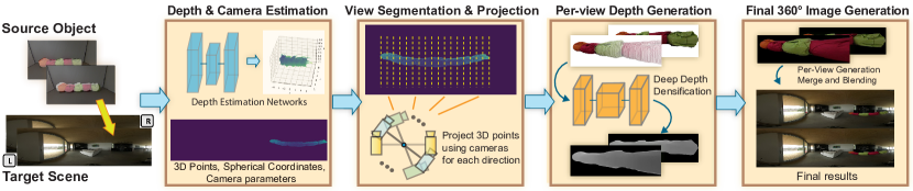
Fig. 3 shows the pipeline of our method for compositing a stereo object into a target omnidirectional stereo background image. There are two key points in our method: Firstly, we manipulate the image content with guidance from 3D space to avoid the distance metric issue in the spherical domain as mentioned in (zhang2021efficient); Secondly and more importantly, we apply view-dependent projection from 3D space to ensure appropriate disparities for different parts of the object. The 3D point clouds of the input stereo object and the target scene are reconstructed from the estimated disparities. According to the desired position and size of the inserted object, we transform the 3D points to a spherical coordinate system with the user’s virtual position as its origin, and segment the point clouds into multiple regions based on the horizontal angle . To generate proper depth perceptions for an arbitrary view direction, we build separate virtual camera pairs focused on each region, and apply view-dependent projections to obtain the initial sparse depth maps on the planar image domain. In our experiment, we find that denser segmentation always leads to higher visual quality. Therefore, we normally choose the smallest interval we can achieve to segment the 3D point cloud, which is the viewing angle covered by one column of the target equirectangular image. We then employ a deep depth densification model to estimate the dense depth maps and their alpha maps for all the view directions. The left and right color images are then generated with the guidance of the depth maps. For each view segment, we find the stereo equirectangular pixels within the segment’s FoV and overwrite them with the corresponding pixels in the generated planar image pair for that view. In addition, our system also overcomes the occlusion problem: during composition, our system can easily get the occlusion relationship between the inserted source object and the background objects. Correct occlusion enhances the natural depth perception, as it prevents depth conflict between the inserted object and the original panorama.
4. Algorithm
The inputs of the method are a pair of stereo images of the object to be inserted, with a masked region-of-interest (RoI), and a stereo panoramic image pair as the target scene. The output is the composited image pair with correct depth perception of the inserted object for arbitrary view directions. The critical challenge is to find a proper binocular camera model to project inserted objects to target panoramic images while preserving correct depth perception. Another challenge lies in the generation of a complete and smooth depth map especially when the desired inserted 3D position is different from the original source position.
4.1. Sparse 3D Reconstruction
We first estimate the depth map of the foreground object and the region around the desired position of the target scene. For inserting the object into the stereo panoramic target scene represented by equirectangular projection, the user is required to specify the position and the size of the object. We project the region-of-interest of the target scene to a planar image with a default FoV of 60° If the source object is in a stereo panorama as well, we use an FoV of no less than 60° to cover the horizontal angle extent of the object when projecting the object into a planar stereo crop. We apply Li et al’s sequence-to-sequence correspondence perspective deep model, named the STereo TRansformer (STTR), to estimate the disparity map from the stereo pairs (li2020revisiting).
Using the predicted horizontal disparities between the input rectilinear stereo image pair, we can generate a depth map of the foreground objects based on camera parameters. Assuming the focal length is and the baseline between the left and right camera is , the depth values for the pixels can be calculated from its estimated disparity : .
Given a pixel on the left-view image with a size of , we assumed a standard camera model located at the origin looking down the -axis. The 3D coordinates of this point in the world coordinate system are obtained by:
| (1) |
In the recovered sparse point cloud from the stereo pixels, we select the center point of the cloud as the object’s reference point to place in the target scene and about which to make any transformations, such as scaling and rotation. It also helps the user to correctly position the object in the target scene. Fig. 4 shows an example of a recovered 3D point cloud.
4.2. View Segmentation and Projection
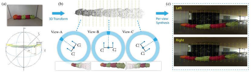
Having determined the transformations needed to meet the user’s desires, including the size, orientation and position of the object, we obtain the 3D point cloud for the object that is to be inserted in the target scene. To address the aforementioned challenge of inconsistent depth, we segment the point cloud into different parts according to the individual points’ directions from the user’s position. As shown in Fig. 4(a), we first transform world coordinates to a spherical coordinate representation by:
| (2) |
Then we segment the point cloud according to the points’ -values: we split the range of into intervals, i.e., each interval covers a range of , and segment the points of the object based on the horizontal angle intervals in which they fall. In our experiments, we found that some segments might only contain too few points when the user-specified pose is largely different with the original pose, because the point cloud was recovered from the view of the original stereo image. Therefore, we produce a dense depth map for the desired pose and scale of the target object using the deep depth densification network proposed later in Sec. 4.3, and then perform view segmentation on the point cloud generated using the dense depth map.
View-Dependent Projection In this step, we treat each segment of the point cloud with a virtual camera pair that focuses on the individual segment’s center. \neilWe generate a series of view-dependent projected point clouds, each in their specific camera space (Fig. 4(b)). The position and orientation of the user’s binocular views are defined as follows. The virtual viewing camera pairs are located on the -plane of the world coordinate system, with up-vector along the positive -axis. The initial position of \neilthe two cameras, and \neilare located on opposite sides of the origin on the -axis with a distance between the two cameras, which are at and , respectively. This initial pair’s viewing directions are parallel to the positive -axis. Given intervals, the system calculates the viewing direction for the th interval as:
| (3) |
Then, the rotation matrix for a such interval is computed based on the viewing direction, which is a rotation about -axis by an angle . We can define the desired position of and with associated viewing direction as:
| (4) |
The projected 3D point cloud of each segment for both views, and with the specific camera matrix are expressed as:
| (5) |
Using the known intrinsic matrix of both cameras for a specific segment, we then project the point clouds to 2D depth maps. The projected depth maps usually contain holes and gaps when the relative pose of the object to the camera changes. \neilThe following steps (see below) thus estimate a dense depth map to guide the generation of stereo RGB images for that view direction. Here, instead of just generating a depth map for the corresponding segment, we also generate sparse depths for the neighbouring regions in a certain field-of-view to facilitate the following dense depth map generation for each view.
4.3. Per-view Depth Generation
To ensure the perceived depths are correct when users are looking at different parts of the composited object, we propose to generate the dense depth maps and corresponding stereo RGB images based on the projected point clouds for each view \neildirection separately. The stereo images for each view \neildirection will be merged together to generate the final left and right panoramas.
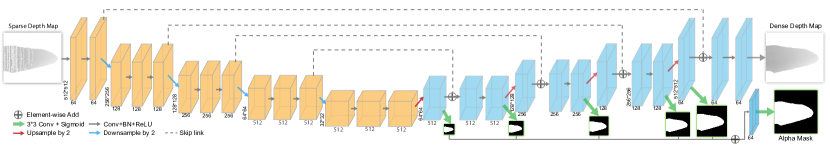
Given \neilthat the desired pose of an object can vary considerably away from the captured pose, the projected depth maps \neilcan be very sparse for \neilsome view directions of the stereo camera pairs. We \neilinitially attempted to directly fill the missing 2D pixels on the depth map by morphological interpolation-based methods as described in (ku2018depthCompletion). However, an interpolation-based method works only when the pose changes are subtle so that the missing points can easily find valid depth values in their neighbourhoods. If the object has a relatively large scaling and rotation, the valid points \neilare too sparse to provide sufficient reference values for the missing pixels to interpolate. Moreover, since we need to generate dense depth maps for each view, the long running time of morphological interpolation \neilhas a large negative impact on efficiency. Thus, we propose a deep depth densification network to solve the above issues when generating new depth maps. We show that our network generates dense depth maps efficiently with higher visual quality, especially for objects with sharp geometry features. \neilTo avoid the distortion in the equirectangular representation affecting the learning process, our deep model works in the 2D rectilinear image domain.
Architecture We build a convolutional generative network that takes a projected sparse depth map as input and predicts dense valid depths and transparencies for the target object. As shown in Fig. 5, a 2D sparse depth map goes through a U-Net-like architecture to produce a densified depth map. More specifically, we employ the following two learning schemes to improve the quality of generated depth maps: First, we explicitly predict a mask that indicates whether a pixel belongs to the target object in the final image, helping the network to learn whether a pixel should have a valid depth value. Second, we let the decoder learn from multi-scale masks to have a better capability of reconstructing the object’s geometry structure. For each scale level, we use a separate convolutional layer, upsampling operation, and sigmoid function to predict the masks at different scales, which are then fused by a concatenation operation at the end with some higher-scale contextual information.
In our experiment, the above schemes are shown to be effective, especially for improving the depth map quality for those regions with large sparsity.
Dataset Since it is tedious and laborious to collect a real-world stereo dataset with multiple views of the objects for training the above network, we build a synthetic dataset with ground truth depth maps of rendered objects. We use Unity3D to render RGB images and their associated dense depth maps with different positions, scales, and orientations. We select 30 classes of 3D shapes in the ShapeNet dataset (chang2015shapenet), covering a variety of categories of furniture, vehicle, housewares, and buildings. In each class, we randomly select 50 objects. For each object, we render 20 different poses, producing 20 dense depth maps, , and their corresponding masks, . The original pose for each object is chosen as its reference pose and a sparse point cloud is reconstructed from its depth map . The transformations, , between the other poses and the reference pose are then applied on to generate the sparse depth maps, . We use the sparse depth map, , to simulate the input data for the real-world use case, where the sparse depth map can be generated by transforming the reconstructed point clouds from the original stereo object to the desired 3D orientation and position. The corresponding dense map, , and mask, , can be used to supervise the learning process.
Training Procedure
The neural networks are trained to fill the gaps and missing points while preserving the important geometry structures for a sparse depth map. We use the following losses in the training procedure:
(1) The reconstruction loss, , an L2 loss applied on the predicted depth map, defined as:
where represents the predicted dense depth map from the sparse map .
\neil(2) The mask loss, . The network generates masks of different scales, which help it to better learn the global structure of the shape. is the loss of these smaller, subsidiary output masks, which is defined as:
where is the ground truth mask for the scale and is the predicted mask for scale .
\neil(3) The perceptual loss, , applied on the depth map to produce better details. \neilThis makes the overall loss:
By default, we set , , and as the weights for different terms. We split our datasets into a training set of 19950 images and a test set of 9000 images. We train our network by 100 epochs or make an early-stop when the losses on the validation data stop declining.
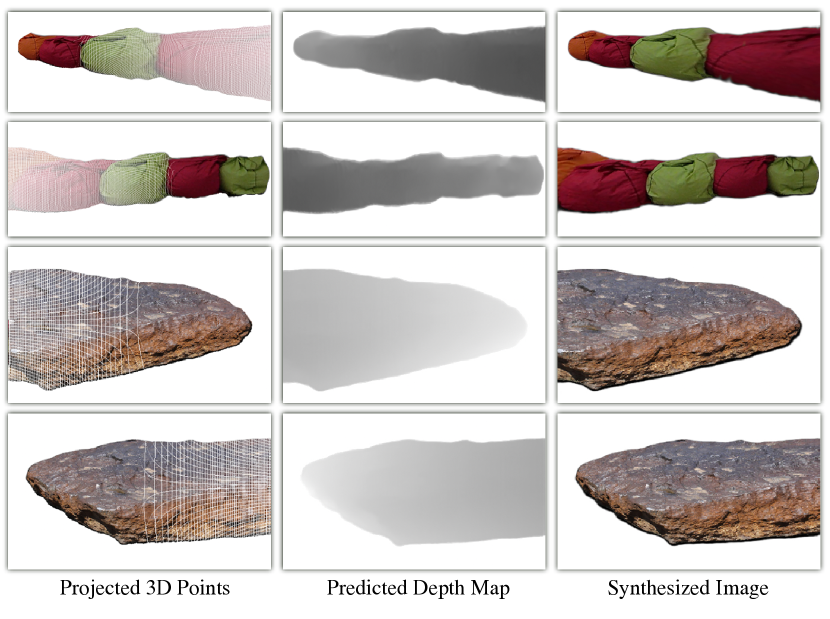
We show some results of our method in Fig. 6 and compare our method with some alternatives in Fig. 7. \neilThese demonstrate that it is hard for interpolation-based methods to properly fill the missing pixels in the boundary parts, since the transformed points can be very sparse in the projected depth map and cannot form any continuous line structures to wrap up the object. The use of the mask losses avoids the depth value “leaking” to pixels that should be outside of the object’s contours, and also makes the network more confident when estimating the depth values for pixels with strong geometry features. Using such a network, we are able to \neilrapidly produce all the dense depth maps where the camera pairs are focused on the centers of different 3D point segments.
4.4. Final Stereo Panorama Generation
Given the dense depth map for each view direction, we re-project each pixel to the original input stereo image to obtain its color value. In the original image, the system applies alpha matting (Germer2020) to generate soft edges for composition. To ensure a seamless composition, we also create an associated alpha mask by copying the alpha value of each referred original pixel. For the segments of the point cloud, we thus obtain stereo image pairs with their alpha masks. To accelerate the process, we \neilgenerate the depth map and stereo RGB images only in the involved part of the object and its neighbouring region, since the other parts, out of the specified view range, will not be used in the final result generation. \neilWe did experiment with feeding the sparse depth map of the \neilentire object into the neural net, but found that this does not produce better quality, but rather reduces the resolution of the focused segment of the object in the resultant image.
We compose the synthesized left and right views of each segment to the left and right views of the target panorama respectively. For stereo panoramas captured by 360° cameras, we obtain their depths using the 360° depth estimation method proposed in (feng2022depth360) to align the 3D scenes of the target and the source images. Then with the camera model introduced in \neilEq. 4, for each pair of cameras , we use \neiltheir view direction and the interval to obtain the affected pixels in the left and right views of the target panorama. Since the columns of an equirectangular image are naturally the pixels of different horizontal viewing angles, we just need to \neilidentify the affected columns and project those spherical pixels to the 2D image plane of the synthesized image or to find the pixels to overwrite the original colors. The pixels’ alpha values will be used to ensure that only valid pixels will be used and seamlessly blended. Finally, depending on whether the inserted region contains background pixels surrounding the object boundary, we optionally perform Poisson Blending (perez2003poisson) on the synthesized regions in the left and right views.
We find that a larger number of segments always means better visual quality. Therefore, in our default settings, the viewing angle intervals are decided by the horizontal resolution of our target panoramic images and are normally set as the viewing angle represented by a single column. For example, for a panorama with a resolution of , \neilwe use and our interval is \neilthus . In our experiments, we found that the per-column synthesis will not introduce artifacts regarding the spatial continuity of the object’s appearance, because the changes between neighbouring columns are subtle and neglectable. Finally, we \neilcan compare the depth of the inserted object with that of the panorama to determine the occlusion relationship for better composition.
5. Experiments and Results
In this section, we evaluate the key parts of our system, demonstrate our stereo image compositing results, and compare them with other stereo composition methods. We also conduct a user study to evaluate the depth perception quality of the generated results.
5.1. Implementation
The source object can be from any \neilkind of stereo images, such as images captured by 2D/360° stereo cameras or rendered stereo images, and single RGB-D images. Our system allows the user interactively to mark their objects of interest and obtain their alpha masks. For consumer-grade stereo cameras for which the intrinsic parameters are available, we can directly use these to offer a better sense of the real-world size of the operated objects. For example, we used and for images captured by a ZED camera. Otherwise, we set some constant values for and for convenience and let the user adjust the object’s size for the stereo data (Xian_2020_CVPR) collected from the internet. When refining the final appearance, gradient-domain methods such as Poisson Editing are provided as an optional operation for users.
On a \neilsingle CPU core of an Intel Xeon E5-1620 with an RTX3090Ti GPU, the average execution time of our method is 7 minutes for generating a composition result with a resolution of using a per-column view segmentation (\neil, 0.09° as the view interval and the object covers an FoV of 90° ), including object segmentation, depth estimation, point cloud processing, view-dependent projection and the final fusion and refinement steps. The computation time reduces linearly according to the number of segments that are needed for covering the inserted object.
5.2. Component Evaluation
5.2.1. Depth adaption vs. One-off composition
We first evaluate our novel composition paradigm working for 360° stereo images, where we perform view-dependent segmentation and generate the stereo content for each segment. Differing from the 2D stereo composition method that takes the stereo contents as input and \neilapplies one-off object insertion operations on the left and right views of the target image, our method is able to generate correct depth perception. A basic requirement for a stereo image pair is that there should be only horizontal disparity for each corresponding pixel pair when the viewer is looking at that point, to fit the layout of human eyes. \neilAny vertical disparity will cause incorrect stereo matching and possible eye strain. Thus, we quantitatively estimate the disparities produced by our view-dependent image generation approach and compare them against the disparities contained in the stereo 360° image pair generated from a single view direction.
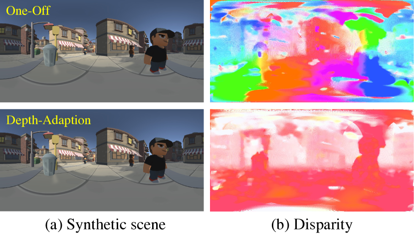
We use Unity3D to generate two synthetic full-FoV stereoscopic results using the depth adaption method and the one-off method, respectively. Using such synthetic data, we are able to avoid possible 3D reconstruction errors when working on real-world data, so that the comparison can \neilfocus only on the generated disparities. We built several 3D scenes. For the one-off method, we use only the initial left and right camera positions described in Sec. 4.2 and render two 360° images as the stereo pair. For our depth adaption method, we segment the 3D scene as in Sec. 4.2 according to the view angle range covered by each column of the panorama, and render the pixels within the view range using the pair of cameras looking at that direction. Then the per-column results are combined together to form the final stereo panorama with view-dependent left and right content. Fig. 8 shows such an example. Note that the per-column method does not introduce any visual artifacts. We use one of the state-of-the-art deep optical flow prediction methods (yuan2021panoof), to measure the displacement of each point between the left and right equirectangular images, since optical flows are essentially the dense correspondences between a pair of images. \neilWe desire that the projected planar images for the user to watch with stereo glass or VR headset contain only horizontal disparities. However, in the equirectangular representation, there might be a minor vertical disparity for a pair of corresponding pixels that only have a horizontal disparity in the planar stereo images, which is caused by the plane-to-sphere projection for the two points with different longitudes. Fortunately, the baseline between the two cameras is normally small compared to the object’s depth, making such a vertical disparity caused by plane-to-sphere projection \neilnegligible, so that we still anticipate that \neilthe user will see only horizontal displacements in the estimated correspondences for the result of our approach.
In Fig. 8, we visualize the estimated dense correspondences between the left and right views of the stereo pairs of both the one-off method and our approach, respectively. We use different hues to show the directions of the displacement vector. Our approach consistently generates only horizontal displacements with different magnitudes. However, the one-off method produces displacements in all directions, with the direction of displacement depending on the object’s depth and distance from the image’s center line. These displacements represent vertical disparity, which causes eye strain. We use the mean-square error (MSE) of the estimated flow vectors as a quantitative metric to measure the difference in the perceived depth quality between the two methods. The MSE of the one-off method’s result is 308.5, which means the perceived depth of the two methods will be considerably different. We also compare the perceived visual quality on real stereo examples in our user study in Sec. 5.5.
5.2.2. Deep Depth Densification
Our deep model for depth densification is built for generating a dense depth map from a sparse projected point cloud. To demonstrate the necessity of the dedicated deep network, we compare it with two possible alternatives: depth map completion methods and point cloud completion methods. Most depth map completion methods are designed for improving the depth map quality of a given RGB-D image. They need a complete RGB image to guide the depth completion, which is not available in our task because the dense RGB image for the desired pose is also missing. Thus, we choose to compare with the method of (ku2018depthCompletion) because it can perform depth completion based on only an input sparse depth map.
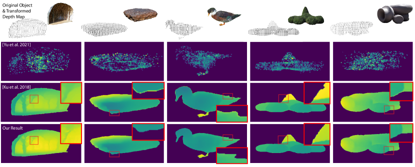
Some results of the depth completion method proposed in (ku2018depthCompletion) are shown in the third row of Fig. 7. However, due to the limitations of their morphological operations when filling the missing pixels, their method fails to maintain geometric details, such as the trees’ edges in the first example in Fig. 7. Their method can also easily propagate incorrect depth values to its neighbours, causing undesirable depth effects like in the boundary regions of the second and fifth examples. Finally, their method may generate incorrect object shapes as in the third and fourth examples, because their method cannot predict which positions have valid pixels of the foreground object. Our deep depth densification method overcomes the above issues and produces higher-quality depth maps. It should be also noted that our method is 6 times faster than the method of (ku2018depthCompletion).
In the comparison between point cloud completion and our deep depth densification, we feed the transformed sparse point cloud to one of the state-of-the-art deep point cloud completion methods, PointTr (yu2021pointr) and project it to generate the depth map for the target view. We found that the point cloud completion method focuses more on the global 3D structure and the integrity of the model and fails to generate sufficient depth details for a specific view. The mandatory sampling step of their method is also a reason for the failure of the dense depth map generation. It cannot guarantee that all the geometric details of the depth map are preserved after the sampling step. Some typical examples are shown in Fig. 7, where our method generates depth maps with significantly better visual quality than PointTr.
We also consider NeRF-based approaches to directly learn to generate novel views. Unlike most NeRF-based approaches that need a number of input views to reconstruct a neural radiance field, PixelNeRF (yu2021pixelnerf) and Depth-Supervised NeRf (deng2022Nerf) only need one or few input images to synthesize new images of novel perspectives. However, PixelNeRF and DSNeRF cannot generate sharp and clear textures from the stereo pair to achieve a satisfactory visual quality for the composition task, since the stereo baseline is normally short, and the depth constraints estimated by structure-from-motion from a stereo pair will be limited. Therefore, we chose to use the densified depth map to guide image generation.
5.3. Results
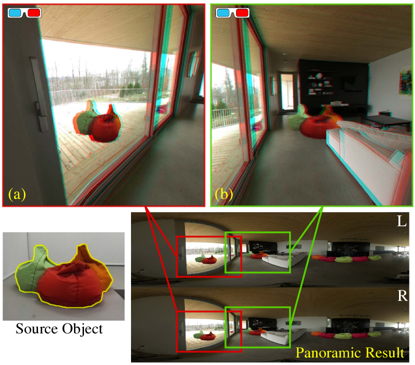
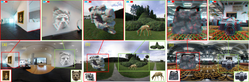
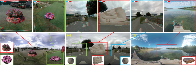
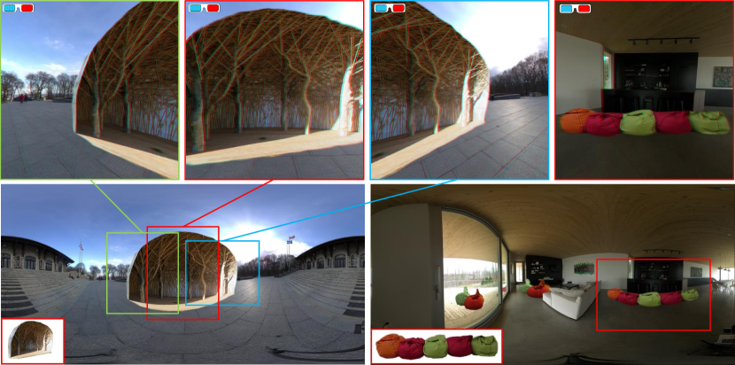
Some composition results of our approach are presented in Fig. 11. For each example, the stereo panoramic scenes are shown at the bottom using the equirectangular projection of its left view. The inset windows demonstrate the segmented source objects and the zoom-in windows visualize the composited stereo objects using anaglyph images. We also include all the stereo 360° results in our supplementary materials, which can be viewed with VR headsets to achieve a better depth perception. From the results where we change the objects’ orientation, size and position, we can see that our method is suitable for processing panoramic images as it is able to recover and manipulate the 3D geometry information to guide the pixel generation. We naturally avoid the computation for adapting to equirectangular distortions when pasting the object into an arbitrary position. We also generate correct panoramic disparities using this 3D-guided approach. Fig. 10 shows a result where we achieve natural composition results by considering the occlusion relationship with the backgrounds. The occlusions between the composited objects and the original object show the depth consistency achieved by our method. In Fig. 11 (a) and (f), we can see the Poisson Blending step can make the color of the object fit the target scene naturally. Our method is particularly suitable for coping with wide objects covering a large FoV, which are more common in 360° image editing tasks. Fig. 12 show two such examples, where our approach achieves correct disparities in the left and right end of the composited objects.
5.4. Comparisons
Directly treating equirectangular images as normal 2D images when applying the image cloning operation cannot generate correct equirectangular distortion, which is important for maintaining the inserted object’s shape when viewing it in a headset or a 360-degree image player. Considering the incorrect equirectangular distortion will also lead to problematic disparities when viewing the region of interest of the result, we therefore do not make further comparisons with the 2D planar image composition methods proposed for monocular 2D images.
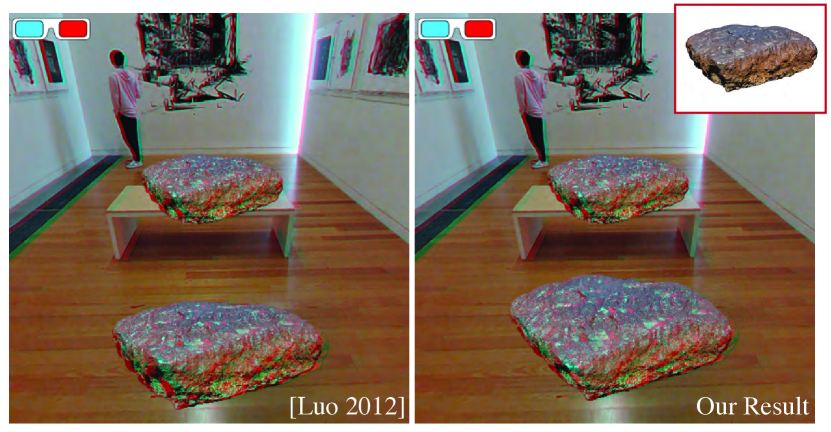
For objects that only cover a narrow FoV, an alternative method to insert stereo objects to the target panoramic scene is \neilto project the relevant part of the panorama to a 2D image plane and \neilto then insert the object \neilinto the planar stereo image before projecting back. The composition methods of Luo et al. (luo2012perspective) and Tong et al. (tong2012stereopasting) are proposed for image cloning and composition in stereo 2D images. The latter method needs a substantial amount of user interaction. Therefore, we choose to compare with the method of Luo et al. that relies on mesh-based deformation to demonstrate the effectiveness of our stereo content manipulation and generation method. In Fig. 13, we show their composited stereo images and the 2D result generated using our deep depth densification and view-dependent content generation. Due to the limited capability of the mesh-based deformation method on the perspective changes of the object, our method can produce more realistic results when the desired orientation and relative position of the target object \neilis notably different from the original capture.
Fig. 9 shows examples of both the one-off method and our method. Viewing the anaglyph stereo images, it is clear that our method produces only desirable horizontal disparities, while the one-off method produces incorrect results that include undesirable vertical disparities. We evaluate the perceived visual quality of the two methods in our user study.
5.5. User Study
We conduct a user study to validate our method subjectively. We used ten panoramic images of different foreground objects. We generated two results for each scene: one result where we directly project all 3D points to the left and right equirectangular image to guide the pixel generation with a fixed pair of cameras (one-off) and the other result using our view-dependent projection, where we choose the FoV of each column of a panoramic image as the interval of our view-segmentation, i.e., 0.09° There were 14 participants (six males, and eight females, aged from 25 to 52). After a short training session using two stereo scenes, the participants were asked to watch the ten groups of two stereo panoramas in Oculus Quest 2, and assess the two panoramas based on the visual quality by giving a score from 1-bad to 5-good. They were also asked to mark three positions where they found the visual qualities were most different between the two shown panoramas. Finally, they were asked to choose one of the two compared panoramas that had better visual comfort. We presented the foreground objects in front of a black background to avoid any confounding factors from a textured or image-based background.
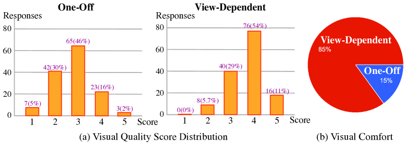
Fig. 14 and Tab. 1 report the user study results. The view-dependent result achieves a much higher mean score than the one-off results which may be attributable to no ghost artefacts being perceived by participants, especially at the boundary or the regions with sharp and clear structures. This is consistent with our intuition that using a large number of segments with small intercepts can benefit the capture of foregrounds by rendering all parts of the foreground from appropriate eye positions. We performed a paired-samples t-test between the scores of the results of the one-off method and our approach. As shown in Tab. 1, the result indicates that the visual quality of our method is significantly better than the one-off method at a significant level . Most of the participants reported that the regions far away from the composited object’s center have noticeable quality differences. Depending on the textures and colors, the participants might have a different level of sensibility to such a difference, which causes a minor variance in the reported positions. In terms of visual comfort preference, the preferred method is our view-dependent approach in 85% of the responses. For more information on the details and results of our user study please refer to our supplementary document.
| Score | Mean | Std | P-Value |
|---|---|---|---|
| One-Off | 2.807 | 0.847 | \multirow2* |
| View-Dependent | 3.714 | 0.742 |
Limitations and Future Work \zfl The proposed approach has three limitations. First, if the depth estimation method fails to predict an accurate depth map of the source stereo object, our image generation method based on depth maps might not be able to produce satisfactory results when the user wants to change the object’s 3D pose due to the incorrect 3D-to-2D projection. Second, our approach does not model the illumination effect of the composited object. In future work, we will reconstruct the lighting information and the 3D geometry of the target scene to illuminate the object. Finally, our current system relies on the user’s input to decide the object’s 3D pose and position. More advanced pose adjustment methods can be potentially employed to create more realistic results.
6. Conclusion
The goal of this paper is to address stereo 360° image composition with desired poses and positions of the inserted object, especially when the user composites an object with desired pose and scale that covers a large FoV into an omnidirectional stereo image. The goal has been achieved by developing a novel composition algorithm that keeps the basic 3D geometry of the composited object, while also achieving a high-quality depth perception for an arbitrary view in the panoramic scene. Particularly, a view-dependent projection method can make the composited content adapt to different view directions. The results show that the composited foregrounds can keep geometry information when the perspective, position or size of the object change. The user study demonstrates our method achieves the highest quality of depth perception when we make the view-dependent projection method with a fine segmentation.