Further author information: (Send correspondence to M. J. Clark)
M. J. Clark: E-mail: mj.clark@bristol.ac.uk
Entanglement distribution quantum networking within deployed telecommunications fibre-optic infrastructure
Abstract
Quantum networks have been shown to connect users with full-mesh topologies without trusted nodes[1, 2]. We present advancements on our scalable polarisation entanglement-based quantum network testbed, which has the ability to perform protocols beyond simple quantum key distribution. [3, 4] Our approach utilises wavelength multiplexing, which is ideal for quantum networks across local metropolitan areas due to the ease of connecting additional users to the network without increasing the resource requirements per user. We show a 10 user fully connected quantum network with metropolitan scale deployed fibre links, demonstrating polarisation stability and the ability to generate secret keys over a period of days with a network wide average-effective secret key rate of bps.
keywords:
Quantum Communication, Quantum Network, Quantum Key Distribution, Entanglement1 INTRODUCTION
In the future landscape of Quantum Technology a method of interconnecting different quantum systems will be required. The prevailing direction is towards a Quantum Internet (QI) [5], constructed by interconnecting Quantum Networks (QNs). QNs have been demonstrated in both metropolitan scale [6, 7] and long distance configurations [8, 9], however most have focused solely on Quantum Key Distribution (QKD) based networks. This has been the case as the most near term application of a QI is QKD. Methods for building QNs beyond simple QKD have been explored and in general are based on Entanglement Distribution (ED). Such QNs have mainly used photon pair sources to distribute entanglement on a metropolitan scale [1] and across long distance [10]. Some have used single photons from local quantum systems to entangle multiple systems over distance [11]. Progress has been made in generating multi-partite entangled photon states [12], but there are still challenges in producing a scalable network while connect many users together.
As Quantum Technology advances a scalable method of distributing entanglement, that allows for multiple simultaneous use cases, is required. Developing ED QNs for a metropolitan scale area with minimised resource overheads is essential, while still allowing for a system to be scaled up to a larger set of users. The QN discussed below is a based on ED and allows for protocols beyond simple QKD. [3, 4]
2 THE QUANTUM NETWORK
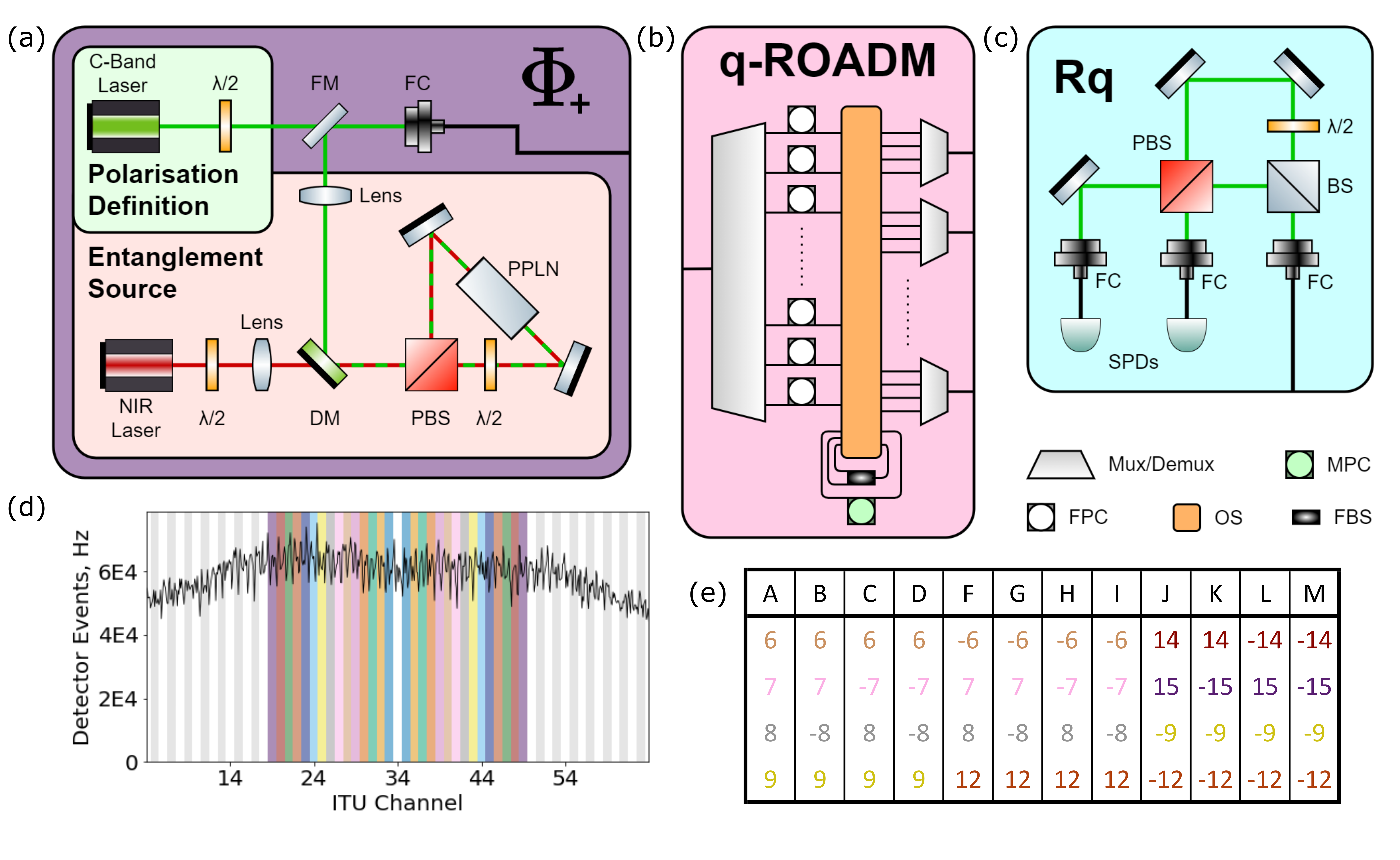
The Entanglement Source (ES) of the QN, shown in Figure 1 (a), is a Sangac Interferometer that produces entangled photon pairs through type-0 Spontaneous Parametric Down Conversion. A continuous wave nm laser is used to produce spectrally non-degenerate photon pairs with a central wavelength of nm. Figure 1 (d) shows the frequency spectrum of the ES output, and how that light is cut into International Telecommunication Union (ITU) channels by the quantum-enabled Reconfigurable Optical Add-Drop Multiplexer (q-ROADM), as shown in Figure 1 (b). The central frequency of the output is at THz, corresponding to ITU channel 34, such that the entanglement is shared pairwise around this channel. We label ITU channels 19 to 49 as Logical Channel (LC) to respectively.
LCs then share entanglement with their negative counterpart. It is key to note here that all ITU channels, in the range ITU and ITU , have 1-to-4 beam splitters applied to them inside the q-ROADM, such that receiving one LC allows a user to communicate with up to 4 other users. This allows a users to receive one LC in this configuration, where 4 would be required in a configuration without splitting. Although this increases the loss on the links by dB, it reduces the resource requirement of the ES and the q-ROADM by requiring fewer ITU channels to connect all users.
Once separated, each split LC travels though a separate Fibre Polarisation Controller (FPC), and finally each set of LCs are combined into a single fibre. A set of LCs are selected for a single user to receive, such that they share entanglement with all other users in the network, as shown in Figure 1 (e). This may be performed dynamically such that the connectivity of a network may be continuously changed. Dynamicity allows for situations where an actively switched network would improve the performance aswell as LC reassignment when network users are changed. The light from the single fibre is then measured by a user inside of a Quantum Receiver (Rq). This measurement has a passive basis choice, preformed by a beam splitter, and then overlaps one of the two measurements from each basis onto one from the other basis reducing the number of Single-Photon Detector (SPD) required at each user. Once all users are receiving photons from the ES, correlations are calculated between every pair in the network, allowing users to generate a Secret Key (SK) through the Bennett-Brassard-Mermin QKD protocol[13, 14], commonly known as the BBM92 protocol.
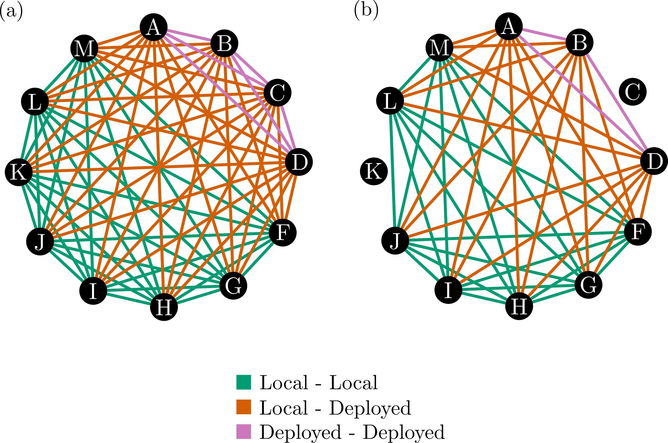
This infrastructure constructs a QN consisting of 12 users with a full mesh topology, as shown in Figure 3 (a). There are four remote users; Alice, Bob, Chloe, and Dave each connected through a deployed fibre link with bounce-back link losses of; dB, dB, dB, and dB respectively. The remaining eight users; Faye, Gopi, Heidi, Ivan, Jo, Kevin, Lea, and Marek are connected through local fibre.
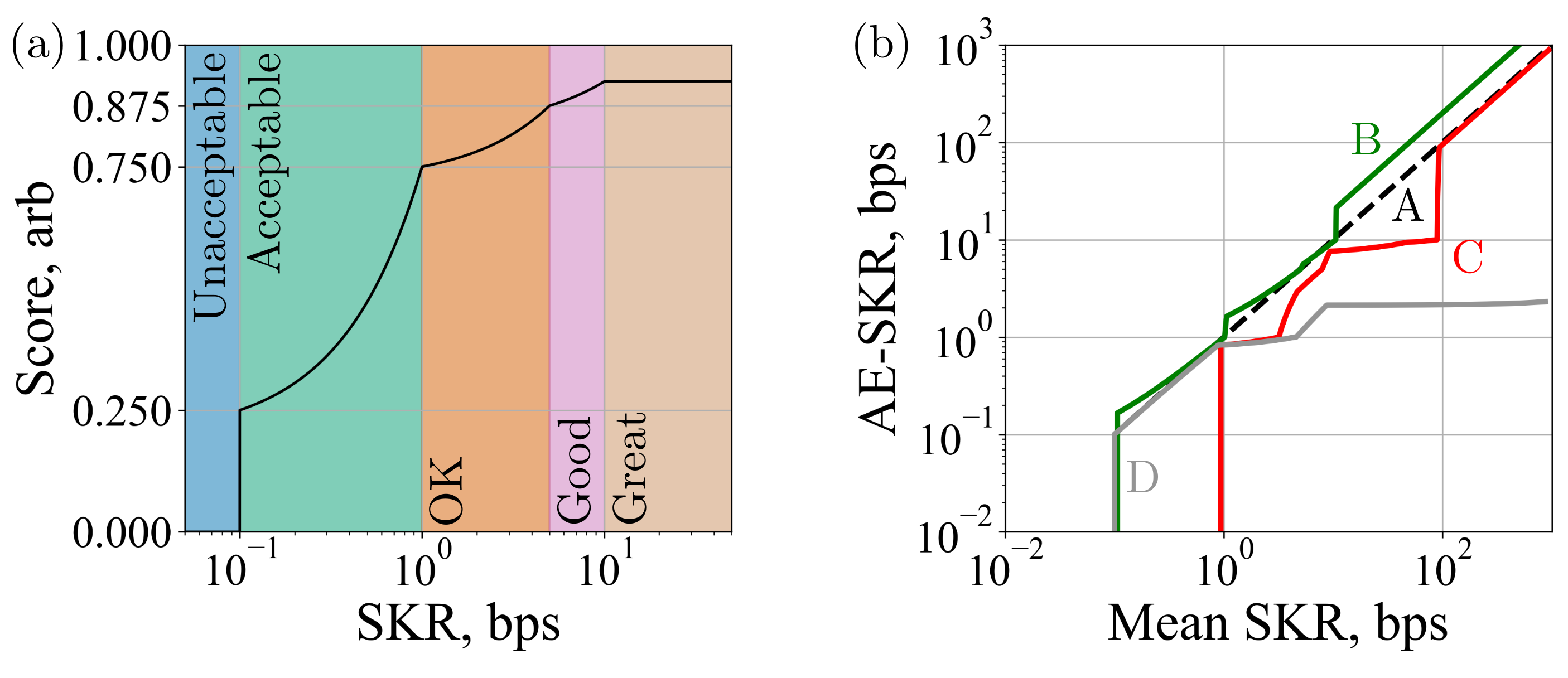
To assess the quality of the network a metric is required. The mean SKRs of a network often ignore links that are non-functional due to the increased SKRs of other links. We select an interpolation function, as shown in figure 2 (a). This allows the choice of a failure condition in the network, here a link with SKR bps, the score would be 0. A network score is then given by;
| (1) |
where is the number of links in the QN, is the SKR of link , and is the interpolation function. To retrieve an analogue to the QN mean SKR, taking the score weighing into account, the inverse of can be applied to . This weighted mean is called the Average Effective Secret Key Rate (AE-SKR). The same process can be followed to generate the AE-SKR of a subgroup of links, such as the connectivity scenario or for a single user. Figure 2 (b) shows how a small number of under-preforming link affects the scaling of a network AE-SKR.
3 RESULTS AND DISCUSSION
| User | Average Visibility |
|---|---|
| Alice | |
| Bob | |
| Chloe | |
| Dave | |
| Faye | |
| Gopi | |
| Heidi | |
| Ivan | |
| Jo | |
| Kevin | Failed |
| Lea | |
| Marek |
In order to show entanglement, and therefore generate a SK, between separated users with a shared ES, the definitions of polarisation must match between Rqs. To do this a canonical method of manual fibre neutralisation is used [15]. This is performed by sending an attenuated classical signal comprised of two orthogonal polarisation definitions, Horizontal (H) and Anti-Diagonal (A) light, to the Rqs from the Polarisation Definition setup, as shown in Figure 1 (a). The average polarisation visibility of each user is provided in Table 1. It is clear that of the users have visibilities above , however Kevin failed the neutralisation steps with an estimated visibility of . Due to the poor quality of the polarisation visibility, Kevin will not be included in the QN. However, it is key to note here that the estimated Quantum Bit Error Rate (QBER) of the Kevin Links were below 0.1, despite the measurement basis orthogonality issue with the Rq. The timing jitter of the SPDs used by Chloe were significantly higher than other users. As such Chloe is deemed to be a failed user and shall not be included in the QN. Although Chloe is a failed user, it is key to note that all links to other users could successfully generate a SK. This is despite the QBER being close to the maximum SK generating QBER, but the SKR quickly dropped below the failure condition due to polarisation drifts. The presented QN is therefore a fully connected 10 user QNs, as shown in Figure 3 (b), with no difference in resource allocation to a fully connected 12 user QN, as shown in Figure 3 (a).
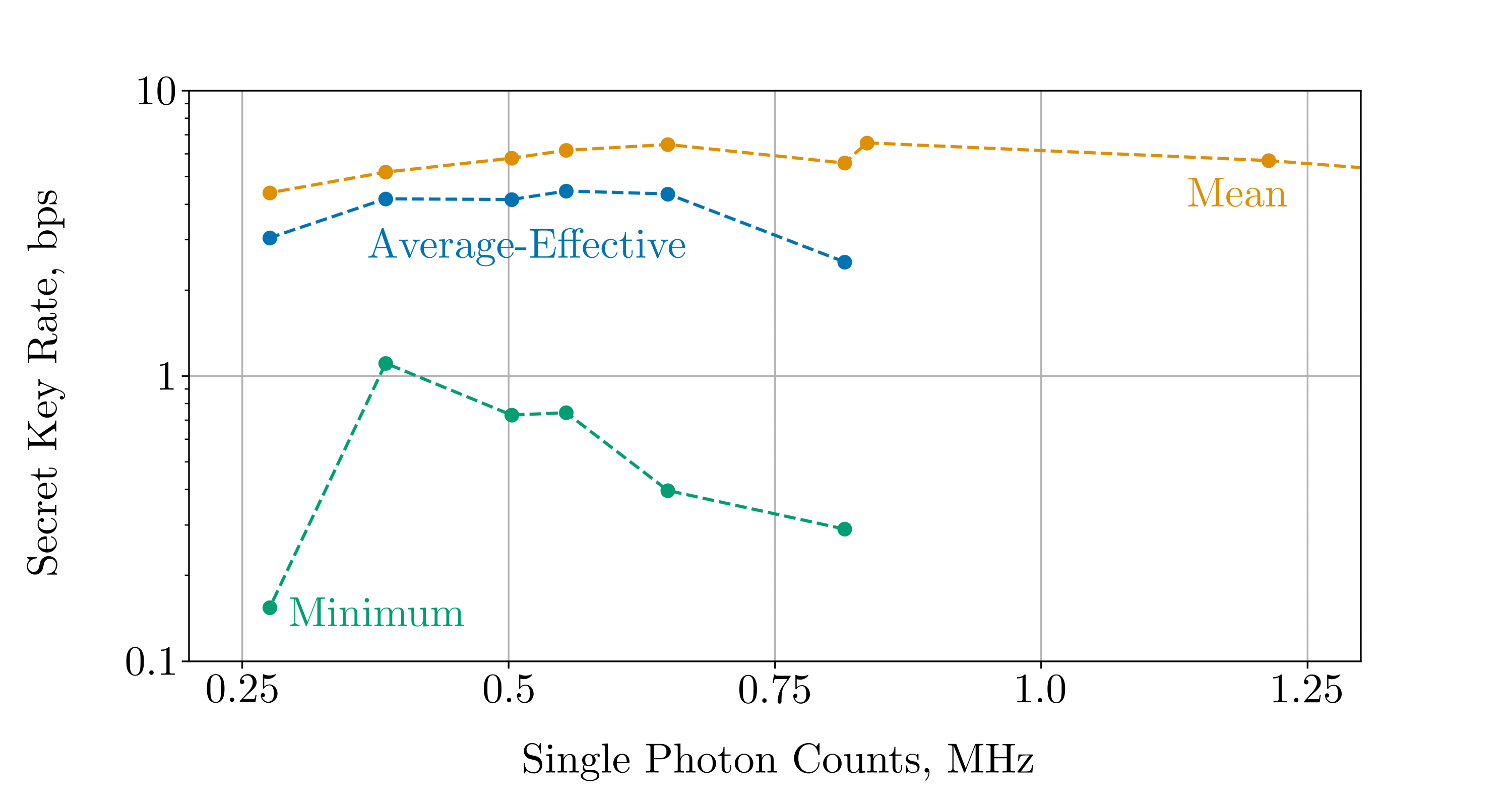
Once all users are receiving entangled pairs and the definitions of polarisation match, the optimal pump power must be found. This is done by adjusting the laser power and measuring the number of single photon counts measured in an unused LC. Here the reference count rate is measured on LC . Figure 4 shows the relation between the reference counts and the SKR. Here it can be seen that the mean SKR remains high for much higher count rates, even past where the minimum SKR is zero. The AE-SKR is consistent between MHz and MHz, so a corrected count rate of MHz was selected for the network.
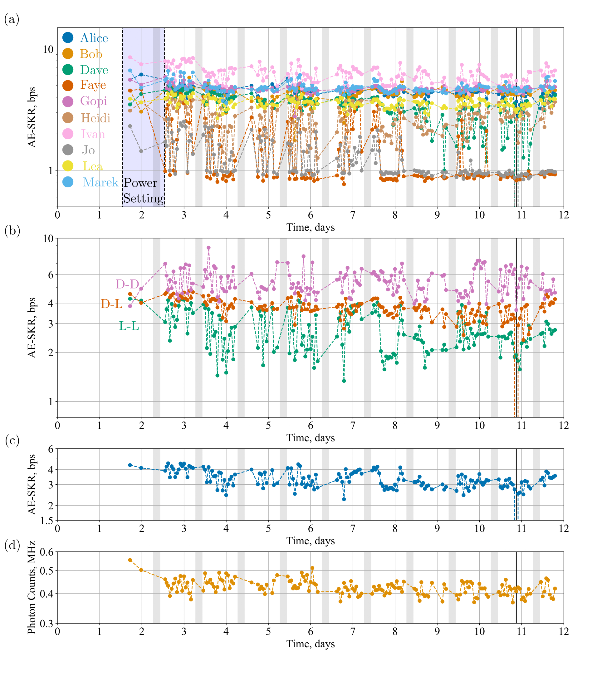
When the Neutralisation of all QN links is complete network up-time is defined to have started. The count rate of the LCs are set between and days, as shown by the blue region in Figure 5 (a). Two data points, closest to the selected pump power, are shown in this region. Most users AE-SKR stays stable across the whole time range. Some users; Faye, Heidi, and Jo, fluctuate in AE-SKR after setup but stabilise after some time. One user, Dave, fluctuates across the whole time set and then the link with user Jo fails after days of network up-time. This point is the Network Failure point, shown in Figure 5 as as the vertical black line, and the network would be reset. Notably, even though the network was deemed to have failed, the failure was reached by one link dropping to bps. As can be seen in Figure 5 (c), the network recovers functionality after the failure condition was reached.
Figure 5 (b) shows the three connectivity scenarios presented in Figure 3 (b). The scenario with the highest AE-SKR was when both users are connected though deployed fibre, with bps, as shown in Table 2. This occurred as the detectors with the highest efficiency and Rqs with the lowest loss were given to the deployed users, therefore higher transmission loss is balanced with the more efficient measurement. The scenario where the AE-SKR was lowest was when both users were connected with local fibre. The stability of all three scenarios is similar with approximately fluctuation from the full time AE-SKR to the minimum and maximum AE-SKR. This demonstrates that across the whole days there was a stable and fully functional user fully connected QN.
| Scenario | AE-SKR | Maximum | Minimum |
|---|---|---|---|
| Alice | |||
| Bob | |||
| Dave | |||
| Faye | |||
| Gopi | |||
| Heidi | |||
| Ivan | |||
| Jo | |||
| Lea | |||
| Marek | |||
| Local-Local | |||
| Local-Deployed | |||
| Deployed-Deployed | |||
| Full Network |
4 CONCLUSION
Here we have demonstrated the setup and operation of a polarisation based 10 user fully connected ED QN, with the resources for a 12 user fully connected ED QN. The QN demonstrated a minimum polarisation stability duration of days through both local and deployed fibre links with network wide AE-SKR of bps, as shown in Table 2. Previously, ED QNs based on entangled photon pairs with passive polarisation compensation, with deployed fibre links have only shown up to a day of continuous polarisation stability before the QN is reset [1]. It is also shown that the links between users with deployed fibres demonstrate similar stability to users with only local fibre links. This improvement in stability indicates that the limitation of metropolitan scale ED QNs is likely to be the polarisation stability of the distribution devices rather than the deployed fibre links. The large concentration of fibre lengths that sit in a relatively small area within the distribution devices leads to large polarisation drifts from small environment drifts. Metropolitan scale deployed fibres do not have a large influence on the stability of a QN, and as such scaling QNs up to arbitrary deployed links should be possible, to the limit of the fibre loss of each link.
Acknowledgements.
This work was supported by the UK Engineering and Physical Sciences Research Council (EPSRC) grants EP/SO23607/1, for the Quantum Engineering Centre for Doctoral Training, Centre for Nanoscience & Quantum Information, University of Bristol, and EP/T001011/1 for the Quantum Communications Hub. This work was supported by the Ministry of Science and Education (MSE) of Croatia [contract No. KK.01.1.1.01.0001]References
- [1] Joshi, S. K., Aktas, D., Wengerowsky, S., Loncaric, M., Neumann, S. P., Liu, B., Scheidl, T., Lorenzo, G. C., Samec, Z., Kling, L., Qiu, A., Razavi, M., Stipcevic, M., Rarity, J. G., and Ursin, R., “A trusted node-free eight-user metropolitan quantum communication network,” Science Advances 6, eaba0959 (9 2020).
- [2] Wang, R., Alia, O., Clark, M. J., Bahrani, S., Joshi, S. K., Aktas, D., Kanellos, G. T., Peranić, M., Lončarić, M., Stipčević, M., Rarity, J., Nejabati, R., and Simeonidou, D., “A Dynamic Multi-Protocol Entanglement Distribution Quantum Network,” in [Optical Fiber Communication Conference (OFC) ], paper Th3D.3, Optica Publishing Group (3 2022).
- [3] Huang, Z., Joshi, S. K., Aktas, D., Lupo, C., Quintavalle, A. O., Venkatachalam, N., Wengerowsky, S., Lončarić, M., Neumann, S. P., Liu, B., Samec, Z., Kling, L., Stipčević, M., Ursin, R., and Rarity, J. G., “Experimental implementation of secure anonymous protocols on an eight-user quantum key distribution network,” npj Quantum Information 2022 8:1 8, 1–7 (3 2022).
- [4] Pelet, Y., Puthoor, I. V., Venkatachalam, N., Wengerovsky, S., Loncaric, M., Neumann, S. P., Liu, B., Samec, Z., Stipčević, M., Ursin, R., Andersson, E., Rarity, J. G., Aktas, D. V., and Joshi, S. K., “Unconditionally secure digital signatures implemented in an eight-user quantum network*,” New Journal of Physics 24, 093038 (10 2022).
- [5] Wehner, S., Elkouss, D., and Hanson, R., “Quantum internet: A vision for the road ahead,” (10 2018).
- [6] Chung, J., Eastman, E. M., Kanter, G. S., Kapoor, K., Lauk, N., Peña, C., Plunkett, R., Sinclair, N., Thomas, J. M., Valivarthi, R., Xie, S., Kettimuthu, R., Kumar, P., Spentzouris, P., and Spiropulu, M., “Design and Implementation of the Illinois Express Quantum Metropolitan Area Network,” arxiv:2207.09589 [quant-ph] (7 2022).
- [7] Chen, T.-Y., Wang, J., Liang, H., Liu, W.-Y., Liu, Y., Jiang, X., Wang, Y., Wan, X., Cai, W.-Q., Ju, L., Chen, L.-K., Wang, L.-J., Gao, Y., Chen, K., Peng, C.-Z., Chen, Z.-B., and Pan, J.-W., “Metropolitan all-pass and inter-city quantum communication network,” Optics Express 18, 27217 (12 2010).
- [8] Tang, B.-Y., Chen, H., Wang, J.-P., Yu, H.-C., Shi, L., Sun, S.-H., Peng, W., Liu, B., and Yu, W.-R., “Free-running long-distance reference-frame-independent quantum key distribution,” npj Quantum Information 2022 8:1 8, 1–8 (9 2022).
- [9] Chen, Y. A., Zhang, Q., Chen, T. Y., Cai, W. Q., Liao, S. K., Zhang, J., Chen, K., Yin, J., Ren, J. G., Chen, Z., Han, S. L., Yu, Q., Liang, K., Zhou, F., Yuan, X., Zhao, M. S., Wang, T. Y., Jiang, X., Zhang, L., Liu, W. Y., Li, Y., Shen, Q., Cao, Y., Lu, C. Y., Shu, R., Wang, J. Y., Li, L., Liu, N. L., Xu, F., Wang, X. B., Peng, C. Z., and Pan, J. W., “An integrated space-to-ground quantum communication network over 4,600 kilometres,” Nature 2020 589:7841 589, 214–219 (1 2021).
- [10] Neumann, S. P., Buchner, A., Bulla, L., Bohmann, M., and Ursin, R., “Continuous entanglement distribution over a transnational 248 km fiber link,” Nature Communications 2022 13:1 13, 1–8 (10 2022).
- [11] Pompili, M., Hermans, S. L., Baier, S., Beukers, H. K., Humphreys, P. C., Schouten, R. N., Vermeulen, R. F., Tiggelman, M. J., dos Santos Martins, L., Dirkse, B., Wehner, S., and Hanson, R., “Realization of a multinode quantum network of remote solid-state qubits,” Science 372, 259–264 (4 2021).
- [12] Avis, G., Rozpȩdek, F., and Wehner, S., “Analysis of Multipartite Entanglement Distribution using a Central Quantum-Network Node,” (3 2022).
- [13] Bennett, C. H., Brassard, G., and Mermin, N. D., “Quantum cryptography without Bell’s theorem,” Physical Review Letters 68, 557 (2 1992).
- [14] Waks, E., Zeevi, A., and Yamamoto, Y., “Security of quantum key distribution with entangled photons against individual attacks,” Physical Review A 65, 052310 (4 2002).
- [15] Peranić, M., Clark, M., Wang, R., Bahrani, S., Alia, O., Wengerowsky, S., Radman, A., Lončarić, M., Stipčević, M., Rarity, J., Nejabati, R., and Joshi, S. K., “Polarization compensation methods for quantum communication networks,” arxiv:2208.13584 [quant-ph] (8 2022).