A universal DNA computing model for solving NP-hard subset problems
Abstract
DNA computing, a nontraditional computing mechanism, provides a feasible and effective method for solving NP-hard problems because of the vast parallelism and high-density storage of DNA molecules. Although DNA computing has been exploited to solve various intractable computational problems, such as the Hamiltonian path problem, SAT problem, and graph coloring problem, there has been little discussion of designing universal DNA computing-based models, which can solve a class of problems. In this paper, by leveraging the dynamic and enzyme-free properties of DNA strand displacement, we propose a universal model named DCMSubset for solving subset problems in graph theory. The model aims to find a minimum (or maximum) set satisfying given constraints. For each element involved in a given problem, DCMSubset uses an exclusive single-stranded DNA molecule to model as well as a specific DNA complex to model the relationship between and other elements. Based on the proposed model, we conducted simulation and biochemical experiments on three kinds of subset problems, a minimum dominating set, maximum independent set, and minimum vertex cover. We observed that DCMSubset can also be used to solve the graph coloring problem. Moreover, we extended DCMSubset to a model for solving the SAT problem. The results of experiments showed the feasibility and university of the proposed method. Our results highlighted the potential for DNA strand displacement to act as a computation tool to solve NP-hard problems.
Keywords: DNA computing; subset problems; NP-hard; DNA strand displacement.
Introduction
The existence of NP-hard problems that cannot be solved in a polynomial time (unless P=NP) has inspired researchers to exploit new computing models. DNA computing, as a novel computing model, leverages the Watson–Crick complementary pairing principle and predictable double helical structure, and has been extensively studied by researchers from various areas, including mathematics [1, 2, 3], computer science [4, 5], and biology [6, 7]. Original work on DNA computing was undertaken in 1994 by Adelman [8], who provided an inspiring theory for solving intractable computational problems with biotechnology, and experimentally verified the principle by a simple example of the Hamiltonian path problem. Adelman’s work created a new computing method for solving combinatorial problems, which is called molecular parallelism by Reif [9]. Although scholars have expressed skepticism toward molecular computation owing to its capability to handle only simple problems [10], this argument was quickly destroyed by Lipton [11], who demonstrated the feasibility of solving the SAT problem by extending Adelman’s method. Recent studies in [1, 12] have shown that DNA computing can solve the graph coloring problem effectively.
In 1998, to simplify the process of solution detection, Roweis et al. [13] proposed a sticker-based model for DNA computation, called the sticker model, involving neither enzymes nor PCR extension. More importantly, the original double-stranded structures can be recovered through memory strands after secondary annealing, which allows for the reuse of the DNA material. Based on the sticker model, in 2002, Zimmermann et al. [14] designed DNA algorithms to solve the counting version of a series of NP-hard problems, including -cliques, independent -sets, Hamiltonian paths, and Steiner trees. Also in 2002, Braich et al. [15] solved a 20-variable instance of the 3-SAT problem based on the separation operation of the sticker model.
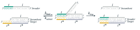
Based on the sticker model, in 2000, Yurke [16] proposed the DNA strand displacement technology, which aims to construct nucleic acid systems with desired dynamic properties. A toehold-mediated strand displacement reaction is described as a molecular dynamic process of replacing a desired single-stranded DNA (called incumbent) from a duplex (i.e., a double-stranded DNA with a sticky end) with an input single-stranded DNA (called invader) that consists of the desired single-stranded DNA and the complementary strand of the sticky end (i.e., the toehold) to create a more stable complex (a double-stranded DNA) [17, 18]. Figure 1 illustrates the principle of the strand displacement reaction. Compared with the traditional self-assembly models, DNA strand displacement can be completed spontaneously at room temperature. Moreover, the DNA strand displacement is enzyme-free, which provides with more flexibility in constructing molecular circuits. Significant literature has been published on DNA strand displacement. In 2011, Qian and Winfree [5] proposed a reversible strand displacement logic gate, called a seesaw gate, based on which they designed a 4-bit square-root circuit containing 130 DNA strands. The seesaw gate has been widely used as a simple building block for constructing large-scale circuits and neural networks [4]. In 2014, Machinek et al. [19] proposed a method of creating mismatched base pairs to achieve the kinetic control of strand displacement. In 2020, Wang et al. [20] designed DNA switching circuits based on DNA strand displacement for digital computing. Moreover, Liu et al. [17] proposed a DNA strand displacement circuit called the cross inhibitor, which is time-sensitive and allows interactive inhibition between two input signals. More recently, leveraging the property of programmable interactions between nucleic acid strands, Jung [6] expanded the capabilities of cell-free biosensors by designing DNA displacement interference circuits. Zhu et al. [21] first experimentally demonstrated that DNA strand displacement could be applied to encryption.
Several studies have utilized DNA strand displacement to solve intractable combinational optimization problems. In 2018, Tang et al. [22] applied DNA strand displacement to solve the 0-1 programming problem, where the model is built based on circular DNA. However, the method is impractical because the number of required species of fluorescence is equal to the number of variables. Therefore, in 2021, the same team [2] designed a chemical reaction network through three reaction modules (i.e., weighted, sum, and threshold) to solve 0-1 integer programming problems. The reliance on fluorescence was reduced significantly. Also Yang et al. [23] proposed a method to solve the SAT problem, which uses a specific origami structure to represent the solutions and detects the solutions by DNA strand displacement.
Although many models of DNA computation have been proposed to solve various types of problems, many of these models were designed to solve only one type of problem. As a result, more energy and effort are required to design distinct models for different problems. Several attempts have been made to reduce the operational complexity by simplifying the models, and great processes have been attained [24, 25]. However, different models require different environmental conditions (e.g., temperature, enzyme, and equipment), which hampers the compatibility between models, even though all these models are simplified extremely. This results in a high cost when using DNA computing to solve different problems, which hampers the popularization of molecular computers with powerful capability, like electronic computers.
To deal with the above challenges, researchers have begun to design universal models of DNA computation. In 2019, Woods et al. [26] utilized tiles to construct an iterated boolean circuit, which can be used to simulate Turing machines [27], universal boolean circuits [28], and cellular automata [29]. In 2020, Wang et al. [20] designed a circuit for digital computation by combining DNA strand displacement and switching circuits, which can be applied to a variety of scenarios, such as molecular full adder [30] and the 4-bit square-root circuit [3, 31]. In 2022, Xie et al. [32] designed a three-way junction-incorporated double hairpin unit by combining single-stranded gates [33] and exponential amplification reaction [34], which can achieve multiple functions and applications, including a 4-to-2 encoder [35], 1-to-2 demultiplexer [36], 1-to-4 demultiplexer [37], and multi-input OR gate.
However, regarding NP-hard problems, previous DNA computing models are still problem dependent, making the development of universal DNA computing models fascinating but challenging. Among NP-hard problems, there are many classic problems, such as the minimum dominating set, the maximum independent set, and the minimum vertex covering, which aim to find minimum or maximum subsets that satisfy some given restricted conditions. These problems belong to the subset problem in graph theory. This paper proposes a universal DNA computing model named DCMSubset for solving these problems. Given a vertex, DCMSubset utilizes the Watson–Crick complementary pairing principle to model the relationship of the vertex by a specific DNA complex. The set of such DNA complexes corresponding to all vertices forms the computation gate circuit of DCMSubset. Different elements (vertex or edge) are represented by different single-stranded sequences. Thus, each element is equipped with a separate detection gate that uses DNA strand displacement reactions to accurately detect the element. To demonstrate the feasibility of DCMSubset, we conducted simulation and biochemical experiments on the above three subset problems, the results of which show the universality of DCMSubset. We observed that graph coloring could also be solved by DCMSubset, which is a direct application of the maximum independent set. Moreover, we extended DCMSubset to a suitable model for solving the SAT problem. The results suggest the potential of DCMSubset to solve a wider range of NP-hard problems.

Results
The principle of DCMSubset. Regarding subset problems, modeling elements and their relations using DNA molecules is fundamental to constructing universal models. This paper focuses on problems related to graphs, where a graph is often described as a 2-tuple (, ) such that represents the vertex set of , and (a set of two-element subsets of ) represents the edge set of . Two vertices are adjacent if and only if they are the ends of an edge of , while a vertex is incident with an edge if and only if the vertex is an end of the edge. Given a vertex , the set of vertices adjacent to is called the neighborhood of , and is called the close neighborhood of ; similarly, the set of edges incident to is called the edge-neighborhood of , and is the close edge-neighborhood of .
The problem we consider in this paper, named -SUBSET[], can be formally described as follows.
Problem 1
-SUBSET[]: Given a graph and a property , the problem asks to find a subset of with the minimum (or maximum) cardinality such that satisfies .
Below is an account of the design of DCMSubset for solving -SUBSET[] problems.
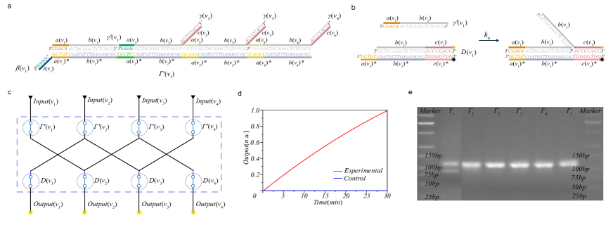
Based on , we first determine the underlying set of the problem; generally, or . For each element , we design a 29-nt single-stranded DNA (denoted by ) to represent it and use a DNA complex (denoted by ) to characterize a relation (that is relevant to , e.g., the adjacent relation and the incident relation) between and other elements. consists of a 5-nt toehold domain , a 16-nt branch migration domain , and a 8-nt branch migration domain . is obtained by binding all s () to a long single-stranded (denoted by ) that consists of a 5-nt toehold at its 3’-end and the complementary strands and of and , respectively, for , where is either or an element associated with . All s for build the computation gate circuit of DCMSubset. To illustrate this modeling method, we consider the star graph , shown in Fig. 2 a, where the vertex set and the edge set . We, for example, consider the adjacent relation and . For , is modeled as a 29-nt single-stranded (see Fig. 2 b) and the close neighborhood of is modeled as a duplex (see Fig. 2 c for an illustration of ).
Each computation gate corresponding to an element receives an exclusive input signal strand (the complementary strand of ) as the invader to displace the incumbent strands, that is, and for , where is an element associated with . See Fig. 2 d for the strand displacement reaction of and , which releases , and a stable double strand (). The computation gate mechanism can be expressed via the following reaction:
To detecte the released single strands by the computation gate circuit, we need a detection gate for each element to recognize the released single strands. For each element , the detection gate of , denoted by , is a duplex that binds an incumbent strand consisting of and to an target strand consisting of and . Here, the incumbent strand carries a fluorophore at its 3’-end, and the target strand carries a quencher at its 5’-end. Because the quencher is close to the fluorophore, the fluorescence is inhibited in . When the invader exists, its toehold binds to the domain of , and branch migration moves gradually to the domain , which releases a single-stranded with a fluorescence signal for monitoring and a stable beacon-labeled double-stranded . See Fig. 2 e and f for the structure of and the strand displacement reaction between and , respectively. All s build the detection gate circuit of DCMSubset for . The detection gate mechanism can be expressed via the following reaction:
DCMSubset consists of computation gate circuit and the detection gate circuit, which work as follows.
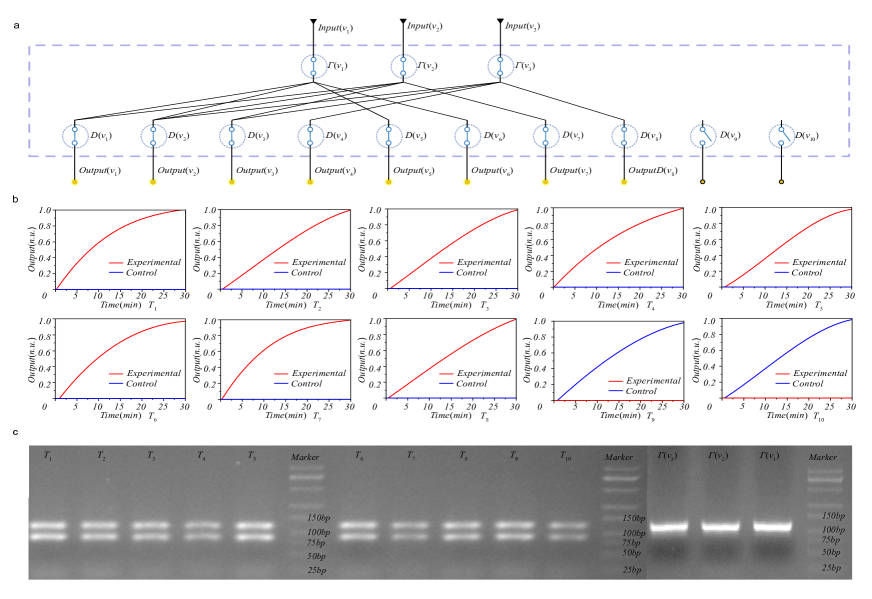
Regarding a -SUBSET[] problem on the underlying set , for the purpose of finding a minimum (or maximum) subset satisfying , we have to traverse over all the subsets of . To determine whether a subset satisfies , we first add the computation gates (), (),…, () into a tube and then divide equally into tubes , , …, . Second, we add the detection gates () into the th tube for . Third, we add all , , to each for and detect the fluorescence signals. It should be noted that computation gates should be designed in compliance with the property ; that is, the design should ensure that is a solution of if and only if the combination of fluorescence signals in all () is a certificate of the property (e.g., the fluorescence signals in all tubes are detected or none of the tubes are detected).
Feasibility of DCMSubset. To verify the feasibility of DCMSubset, we conducted a biochemical experiment for detecting the close neighborhood of the vertex in the Peterson graph P (as shown in Fig. 2 g). We first designed the input strands , computation gate (), and detection gates , , , and ; see Supplementary Table S1 and S2 for the details of these strands. To verify that () can release single strands and , we found it sufficient to prepare four tubes (say and ) such that contains the mixture of and for . For each , we first added (10 1 ) and the computation gates (10 2 ); then, we added (10 1 ); finally, all were put into a fluorescence quantification PCR machine for detecting the fluorescence output. The experimental results are shown in Fig. 2 h, from which we can see that the fluorescence signals in all these tubes are captured.
In addition, we can observe that the strand displacement reaction for (Eq. (2)) is triggered by the toehold domain and proceeds from the branch migration domains and ; the input strand for (Eq. (1)) contains and ; contains , , and . Therefore, two kinds of experiments were carried out to analyze the possible leakage reactions: (1) the reactions of and for ; and (2) the reactions of and for and .
Regarding the first kind of experiment, we prepared four tubes ( ). For each tube , we added the mixture of (15 0.67 ) and (15 0.67 ). Regarding the second experiment, we prepared 12 tubes denoted by ( and ), to which we added (15 1.33 ) and (15 0.67 ). To monitor the fluorescence signals, we put all the tubes and into the fluorescence quantification PCR machine. It can be seen that no fluorescence signal is detected in all these tubes (see Fig. 2 i and j). This indicates that the possible leakage reactions in DCMSubset do not affect the accuracy of the detection gate.
Below is the applications of DCMSubset to three important subset problems in graph theory: the minimum dominating set, the maximum independent set, and the minimum vertex cover. All graphs considered in the paper contain no loop or parallel edge, i.e., simple graphs.
Application to minimum dominating set. Given a graph , a dominating set (DS) of is a subset of such that every vertex in is adjacent to a vertex in .
Problem 2
The minimum dominating set (MDS) problem requires finding a DS of the minimum cardinality.
We used DCMSubset to find an MDS of the Peterson graph shown in Fig. 2 g. In order to reduce costs, we first dealt with the solution space by some preprocessing with a theoretical guarantee. We needed the following two results, where Proposition 1 follows directly from the definition of DS, and Proposition 2 was obtained by Bruce [38] in 1996.
Proposition 1
If is a DS of a graph , then , where .
Proposition 2
Let be an MDS of a graph such that every vertex is adjacent to at least three vertices. Then, .
As for any vertex of , it has for any with . Thus, according to Proposition 1, any dominating set of contains at least three vertices. Moreover, by Proposition 2, we know that any MDS of contains exactly three vertices. Therefore, the solution space is the set of all 3-subsets with cardinality ; that is, . For description convenience, we used , to denote the 120 candidate solutions in .
We now focus on finding an MDS of using DCMSubset. As previously mentioned, for , is modeled as a single-stranded that consists of three parts: , , and . The adjacent relation of is modeled as a duplex (i.e., the computation gate of ), which is hybridized by for all and a long single-stranded , where consists of a 5-nt toehold and the complementary strands of and . The detection gate is a duplex that is hybridized by a single strand consisting of and and a single strand consisting of the complementary strands of , , and . See Supplementary Tables S1 and S2 for the details of these strands.
The experiments are described as follows. We prepared 120 groups of experiments for testing the solution space, where each group consists of 10 tubes. The th group of experiments was used to determine whether is an MDS of . We use to denote the th tube in the th group, where . We first added (12.5 l 1.1 M) and the three computation gates and (each 4 l 5.5 M) corresponding to the three vertices in to each tube . Then, we added , and (each 2.5 l 5.5 M) to . Finally, all tubes were put into the fluorescence quantification PCR machine for detecting the fluorescence output. See Fig. 3 a for the diagram of the first group of experiments, which corresponds the candidate solution = {, , }.
According to the above discussion, a vertex for some implies that must be released by the displacement reactions of and . Therefore,
Theorem 1
The th candidate solution is a DS of if and only if the fluorescence signal in is detected for all .
Here, we emphasize that we stopped our experiments as soon as a solution was found, and all groups of experiments were conducted similarly (if all the 120 groups of experiments were implemented, then all of the MDS of could be found). Thus, only 12 groups of experiments were implemented, corresponding to the inputs (candidate solutions) , , , , , , , , , , , and . By Theorem 1, , is a DS if all of the 10 tubes of the th group of experiments output fluorescence signals. Figure 3 b shows the result of fluorescence detection of the first group of experiments, in which the ninth and tenth tubes do not yield a fluorescence signal, which implies that is not a DS of . The results of fluorescence detection of the other 11 groups of experiments are shown in Supplementary Fig. S1–S3, from which we see that is a DS of and also an MDS of .
To test that the experiments can produce the desired outcomes (double-stranded in Eq. (1)), we separately carried out agarose gel electrophoresis experiments for pure and the mixture of and . Figure 3 c shows the experimental results corresponding to the three inputs , and (the results of the other 11 groups of experiments are shown in Supplementary Fig. S3), from which we see that a new band between 75 bp and 100 bp is produced in the mixture solution, while no new band is produced in the pure solution. This result is consistent with the design of DCMSubset because the double-stranded structure formed by the strand displacement reaction of and (Eq. (1)) has the length 89 bp.
Application to maximum independent set. Given a graph , an independent set (IS) of is a subset such that any two vertices in are not adjacent.
Problem 3
The maximum independent set (MIS) problem requires finding an IS of the maximum cardinality.
We used DCMSubset to find an MIS of Peterson graph (see Fig. 2 h). Analogously, we first reduced the solution space by some preprocessing with theoretical guarantee. We utilized the following two results: Proposition 3 follows directly by the pigeonhole principle and the fact that the set of vertices with the same color is an independent set; Proposition 4 was obtained by Lovász in 1979 [39].
Proposition 3
Let be an IS of an -vertex graph . Then, , where is the chromatic number of , that is, the minimum number of colors assigned to the vertices of such that no two adjacent vertices receive the same color.
Proposition 4
Let be an MIS of an -vertex graph . Then, , where is the adjacency matrix of , and and are the maximum and minimum eigenvalues of , respectively.
As the chromatic number of a graph that is neither isomorphic to (the complete graph on four vertices) nor an odd cycle is at most the maximum degree [40], it follows that , so any MIS of contains at least four vertices, according to Proposition 3. Additionally, the maximum and minimum eigenvalues of the adjacency matrix of are 3 and -2, respectively, which implies that an MIS of contains at most four vertices, according to Proposition 4. Therefore, an MIS of contains exactly four vertices, and the solution space is the set of all 4-subsets with the cardinality =210; that is, = {{, , , },{, , , },…,{, , , }}. We use , to denote the 210 candidate solutions in .
We now focus on the experiment of finding an MIS of base on DCMSubset. All key components were designed in a manner similar to the MDS problem except for a slight change to the computation gate . Here, each was modified by just deleting the component of at the 5’-end, and the other components were unchanged. We denote as the new computation gate; see Fig. 4 a for . The experiments were conducted as follows. We prepared 210 groups of experiments for testing the solution space, where each group used one tube. The th group of experiments (denoted by ) aimed to determine whether is an MIS of . Suppose that = . We first added the four detection gates , , , (each 5 0.916 ) and the four computation gates , , and (each 5 1.832 ) to . Then, we added , , and (each 5 0.916 ) to . Finally, was put into a fluorescence quantification PCR machine for detecting the fluorescence output. See Fig. 4 c for the circuit diagram of the first group of experiments, which corresponds to the solutions = {, , , }.
It is clear that if an arbitrary vertex is adjacent to one of and , then () is released by () for some and then detected by ; moreover, if is an IS, then no () for is released by () for any . We can observe that and can only produce a partial strand of () that consists of only and , denoted by . Also, and do not produce fluorescence signals (see Fig. 4 b). Therefore, the following result holds.
Theorem 2
The th candidate solution is an IS of if and only if no fluorescence signal is detected in .
Also, we stopped our experiments as soon as a solution was found. Thus, we only conducted 49 groups of experiments, corresponding to the candidate solutions {,,,}, {,,,}, {,,,}, {,,,}, {,,,}, {,,,}, {,,,}, {,,,}, {,,,}, {,,,}, {,,,}, {,,,}, {,,,}, {,,,}, {,,,}, {,,,}, {,,,}, {,,,}, {,,,}, {,,,}, {,,,}, {,,,}, {,,,}, {,,,}, {,,,}, {,,,}, {,,,}, {,,,}, {,,,}, {,,,}, {,,,}, {,,,}, {,,,}, {,,,}, {,,,}, {,,,}, {,,,}, {,,,}, {,,,}, {,,,}, {,,,}, {,,,}, {,,,}, {,,,}, {,,,}, {,,,}, {,,,}, {,,,}, and {,,,}, where {,,,} is an MIS, while the others are not ISs of . Figure 4 d shows the result of fluorescence detection of the first group of experiments, which implies that is not an IS of . Figure 4 e shows the result of agarose gel electrophoresis of the first group of experiments. The results of the other 48 groups of experiments are shown in Supplementary Figs. S4–S5, from which we see that is an IS of and an MIS of .
As a direct extension, we observe that the DCMSubset circuit can be used to solve the -coloring problem, which requires us to determine whether there exists an assignment of colors to the vertices of a graph such that no two adjacent vertices receive the same color. As such an assignment is a -coloring of if and only if every set of vertices that receive the same color is an IS of , it is enough to enumerate all -partitions of (i.e., divide into disjoint subsets), and for each -partition (where and for and ), we can determine whether (for ) is an IS of using the DCMSubset circuit for the MIS problem. If is an IS for all , then corresponds to a -coloring (vertices in is colored with ); otherwise, does not correspond to a -coloring, and we consider the next -partition.
Below we argue the applications of DCMSubset to the minimum vertex cover problem. As the experiments were implemented in the same way as the MDS problem, we only verified the correctness of the designed circuits by simulation experiments.
Application to minimum vertex coverage. Given a graph , a vertex covering (VC) of is a subset such that each edge is incident with at least one vertex of .
Problem 4
The minimum vertex covering (MVC) problem requires us to find a VC of the minimum cardinality.
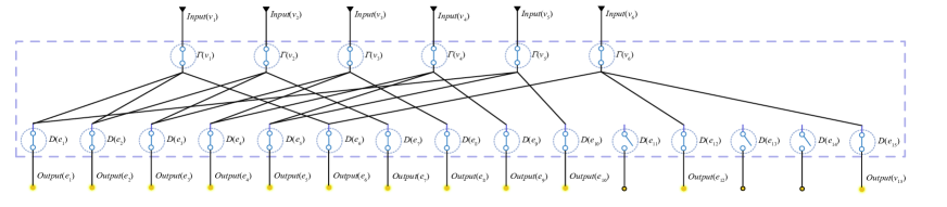
Next, we constructed the DCMSubset circuit for finding all MVCs of the Peterson graph . Because an MVC involves both vertices and edges of a graph, we had to model both of these two types of elements. While all of the key components of the circuit were designed in the same way as that for the MDS problem, single-stranded and complex , for were added to model the edges of and their detection gate. Moreover, each computation gate , , indicating the incident relation, was hybridized by for and a long single-stranded consisting of a 5-nt toehold and the complementary domains of and . Here, , , and are the three edges that are incident with . See Supplementary Fig. S8 for the illustration of .
For an -vertex graph , it is well known that (first observed by Gallai [41] in 1959), where and are an MIS and MVC of . Therefore, an MCV of contains six vertices, and the solution space is the set of all 6-subsets of with the cardinality . Let .
The simulation experiments were implemented as follows. We prepared 210 groups of experiments. For each , the th group of experiments involves 15 specific experiments, for the purpose of determining whether is an MVC of . We use to denote the th experiment in th group, where . Let . For each group , we first added (), then the six computation gates (each ), and finally the six inputs (each ), where . To assess whether is a VC, we detected the concentration of the output signal using DSD simulation tool. See Fig. 5 for the circuit of the first group of experiments, which corresponds to the inputs for .
Through the above analysis, we obtained the following result.
Theorem 3
is a VC of if and only if the concentration of the output signal in is detected for all .
We conducted 210 groups of simulation experiments, corresponding to the 210 candidate solutions {,,,,,}, {,,,,,}, , {,,,,,}, where {,,,,,}, {,,,,,}, {,,,,,}, {,,,,,}, and {,,,,,} are MVCs. The simulation results are illustrated in Supplementary Figs. S11–S17.
Discussion
We demonstrated that DCMSubset could be applied to subset problems in graph theory. In contrast with previous DNA computing models, DCMSubset is more general.
Splitting computation gates. We observed that when a vertex had a big neighborhood, the single-stranded in the computation gate was significantly longer. This may increase the likelihood of error in the process of molecular assembly. We attempted to solve this problem by a splitting method with regard to computation gates. Consider the computation gate shown in Fig. 2 c, which is obtained by binding , to a single-stranded . It is clear that the length of increases with the increase of . We controlled the length of by splitting into subsets with a similar cardinality. We took as an example to show the splitting method, and other cases could be dealt with similarly. First, construct a covering of that consists of three subsets , and , where and . Then, the computational gate (see Supplementary Fig. S10 a) of is split into three components (see Supplementary Fig. S10 b), (see Supplementary Fig. S10 c), and (see Supplementary Fig. S10 d), where for , is the duplex hybridized by all for and a single-stranded that consists of a 5-nt toehold at its 3’-end and the complementary strands of and for . Here, a slight change to and should be done by deleting the domain from their strand (we use to denote the remainder of after deleting its domain). Correspondingly, the input single-stranded is replaced by three short single strands , , and (see Supplementary Fig. S10 e), where is the complementary of , for . Because and do not produce fluorescence signal (see the previous experiments for the MIS problem, as shown in Fig. 4 b), the strand displacement reaction for computation gate (Eq. (1)) can be replaced by the following three reactions.
Application to SAT. In the previous sections, we demonstrated that DCMSubset can be used to solve subset problems in graph theory. To further extend the scope of its applicability, we attempted to solve other problems by DCMSubset. A DCMSubset-based approach for the SAT problem is described as follows.
Problem 5
The SAT problem aims to determine whether there is a truth assignment of 0 (‘false’) or 1 (‘true’) to a set of boolean variables that makes a conjunctive normal form (CNF) true, where for and () is called a literal, which is either or the negative of for some .
It is clear that has true value if and only if every clause has true value. Our target is to design a DNA circuit based on the method of DCMSubset to determine the truth value of each clause for a given truth assignment to the boolean variables.
Unlike in the models for graph problems, for each , we used single strands and (see Supplementary Fig. S6 a) to present and , respectively. Here, and were designed as follows: In the direction from 5’ to 3’, consists of a toehold domain and two branch migration domains and ; consists of the complementary domains , , and of , , and . Observe that although the bases between and are complementary along the 5’ to 3’ direction, they are not hybridized into a double strand owing to the restriction of their directions.
The computation gate was designed for each clause , , obtained by binding all for (here, = if the corresponding literal is the negative form of ; otherwise, =) to a single-stranded , via the toehold domain (or ) and branch migration domain (or ). Note that was designed different from the previous design; we reserved a toehold domain for every ; see Supplementary Fig. S6 c.
Now, for each truth assignment , where represents the truth value of the variable , we designed input strands (see Supplementary Fig. S6 b), as follows: When , is denoted by , which (in the direction from 5’ to 3’) consists of the toehold domain and the complementary domains and of and , respectively; when , is denoted by , which (in the direction from 5’ to 3’) consists of the toehold domain and two branch migration domains and . For the same reason as that for and , and cannot hybridize into a double-stranded complex.
Each computation gate receives input signal strands , ) as the invader to displace the incumbent strands , where ). If and only if and have the same symbol (i.e., either and , or and ), the incumbent strands can be replaced by the strand displacement reaction of this group of inputs and .
The detection gate was designed for each literal in , , , which is obtained by binding the target strand (a complementary strand of ) to a single-stranded output, via the branch migration domains (or ) and (or ). When the invader exists, the strand displacement reaction of and can occur and produce an output single. Supplementary Fig. S6 d illustrates the work flow diagram of DCMSubset on SAT. In Supplementary Fig. S6 c, we give a molecular implementation of the DCMSubset circuit for the SAT problem.
For each truth assignment , we carried out groups of experiments to determine the truth value of each clause . denotes the th group of experiments. Regrading each group of experiments, we added (), for (each ), and inputs corresponding to the truth assignment (each and total ) to . Then, we detected the content change of output signal by DSD simulation. According to the above analysis, the truth value of is true if and only if the output content increases in . Therefore, is true under if and only if the output content increases in all these groups of experiments. See the supplementary case analysis for an example of solving the SAT problem.
Based on our results, we posit that DCMSubset can also be used to design DNA circuits for other classes of NP-hard problems, such as the Hamiltonian problem, which we will attempt to realize in our future work.
Methods
Materials and apparatuses. The DNA oligonucleotides (oligos) used in this study were purchased from Sangon Biotech (Shanghai). All DNA oligos were purified by Sangon using HPLC. Agarose, 10TE Buffer, 50TAE Buffer, 4S Green Plus Nucleic Acid Stain, Sterilized ddH2O, and DNA Marker A (25-500bp) were purchased from Sangon Biotech. The DNA loading buffer (6) was purchased from biosharp (Guangzhou). The concentration of DNA oligonucleotides was measured using a NanoPhotometer@ N120 (Implen, Munich, Germany). All samples were annealed in a polymerase chain reaction thermal cycler (Thermo Fisher Scientific Inc., USA). The PCR analyses were carried out in QuantStudio 3, using the QuantStudio Design Analysis Software v.1.5.1 (Applied Biosystems, MA, US). Agarose gel electrophoresis was carried out in BG-subMINI with BG-Power 600 (BayGene, Beijing). The DNA image on the gel was taken on AlphaImager HP (Protein Simple, San Jose, CA) gel documentation system.
Individual unlabeled DNA oligos were dissolved in 1TE buffer (nuclease free, pH 7.88.2) containing 12.5 mM Mg2+ to a final concentration of 100 M according to the information provided by the supplier, and stored at 4 ∘C. Oligos labeled with dyes or quenchers were dissolved in Sterilized ddH2O to a final concentration of 100 M, according to the information provided by the supplier, and stored in light-proof tubes at 4 ∘C.
DNA sequences. All the DNA sequences used in our study are listed in Supplementary Tables S1 and S2. The DNA sequences were designed to meet several requirements: (a) To balance the reaction rate, the GC content of all DNA strands was maintained at 50 70; (b) We ensured the stability of the formed molecule; (c) To reduce the leakage of logic gates in the DCMSubset model, we avoided duplication of three consecutive bases at the same position in all toehold domains. Initially, the original sequences were obtained by using Nupack, and were then modified by hand.
Molecular Assembly. All sequences that were assembled had to be checked to ensure that no secondary structures affecting strand displacement were generated. We found by NUPACK check that the generation rate of all logic gate secondary structures was not higher than 0.2 at 37∘C. Here, we used the NUPACK to obtain the minimum free energy structure (listed in Supplementary Table S3), where the relevant parameters required for simulation are shown in Supplementary Table S4. All (x) complexes and complexes (listed in Supplementary Table S1) were assembled by mixing the corresponding single strands with equal molar concentrations and equal volumes. Moreover, all (x) complexes (listed in Supplementary Table S1) were assembled by mixing the corresponding single strands using the concentration ratio (x)∗: = 1.1 : 1. Depending on the buffer for dissolving (x)∗ and (which was sterilized ddH2O), to ensure the same ion concentration of (x) and (x), we added an additional TAE containing 37.5 mM Mg2+ to neutralize the ion concentration when assembling (x), in addition to mixing (x)∗ and . Further, (x)∗, , and TAE/Mg2+ were mixed with equal volume. We obtained the concentrations of the diluted DNA single strands using the instrument. We took two approaches to ensure the accuracy of the measured concentrations: (1) the solution was fully shaken and centrifuged before each measurement; and (2) three measurements were taken and averaged as the final concentration used.
Considering that length and number of single strands were different for the assembled computation and detection gates, we use two different annealing procedures to assemble logic gates. The computation gates (x) and were first held at 95∘C for 3 minutes, then cooled to 60∘C at a rate of 1∘C/min, and then cooled to 4∘C at a rate of 0.33∘C/min. Finally, the computation gates were stored at 4 ∘C. The detection gates were first held at 95∘C for 3 minutes, then cooled to 35∘C at a rate of 0.6∘C/min, and then cooled to 4∘C at a rate of 1∘C/min. Finally, the detection gates were stored in the dark at 4∘C. These steps were performed on a PCR thermal cycler.
Agarose gel electrophoresis. The DNA solutions were analyzed in a 5 Agarose gel in a 1 TAE buffer after running for 25 min at a constant power of 110 V using BG-subMINI and BG-Power 600, and imaged with the gel documentation system. 1 TAE was obtained by using ultrapure water to dilute 50 TAE. To prevent DNA samples from running out of the gel during electrophoresis, we used a DNA loading buffer (6) (2l) to color the DNA samples (8l) before performing electrophoresis. Also, we used DNA Marker A (25-500bp) (7l) as a reference for the DNA samples (10l).
The 5 agarose gel was prepared as follows: First, agarose (2.5 g powder) was dissolved in a 1TAE buffer (50 ); then, it was heated until the powder was completely dissolved, and 4S Green Plus Nucleic Acid Stain (10 l) was added to dissolve it fully; finally, it was poured into a membrane tool with a comb and cooled into a solid before being prepared for use.
Simulation and fluorescence kinetics experiments. Simulation for dynamic analysis was completed by Visual DSD. The simulation duration was set to 600 s.
All fluorescence kinetic detection was performed using the QuantStudio 3 equipped with a 96-well fluorescence plate reader. The fluorescence detection procedure was as follows: First, in the Hold Stage, the temperature was decreased to 4 ∘C by a rate of 1.6 ∘C per second, and then the sample was quickly put into QuantStudio 3; second, in the PCR Stage, the temperature was increased to 23 ∘C by a rate of 3 ∘C per second; finally, the fluorescence intensity of the sample was measured every 3 min at 23 ∘C.
References
- [1] Xu, J., Qiang, X., Zhang, K., Zhang, C. & Yang, J. A DNA computing model for the graph vertex coloring problem based on sa probe graph. \JournalTitleEngineering 4, 61–77 (2018).
- [2] Tang, Z. et al. Solving 0–1 integer programming problem based on DNA strand displacement reaction network. \JournalTitleACS Synthetic Biology 10, 2318–2330 (2021).
- [3] Benenson, Y. DNA computes a square root. \JournalTitleNature Nanotechnol 6, 465–467 (2011).
- [4] Xu, J., Chen, C. & Shi, X. Graph computation using algorithmic self-assembly of DNA molecules. \JournalTitleACS Synthetic Biology 11, 2456–2463 (2022).
- [5] Qian, L., Winfree, E. & Bruck, J. Neural network computation with DNA strand displacement cascades. \JournalTitleNature 475, 368–372 (2011).
- [6] Qian, L. & Winfree, E. Scaling up digital circuit computation with DNA strand displacement cascades. \JournalTitleScience 332, 1196–1201 (2011).
- [7] Jung, J. K., Archuleta, C. M., Alam, K. K. & Lucks, J. B. Programming cell-free biosensors with DNA strand displacement circuits. \JournalTitleNature chem biol 18, 385–393 (2022).
- [8] Jung, J. K. et al. Cell-free biosensors for rapid detection of water contaminants. \JournalTitleNature biotechnol 38, 1451–1459 (2020).
- [9] Adleman, L. M. Molecular computation of solutions to combinatorial problems. \JournalTitleScience 266, 1021–1024 (1994).
- [10] Reif, J. H. Parallel molecular computation. In Proceedings of the seventh annual ACM symposium on Parallel algorithms and architectures, 213–223 (1995).
- [11] Lo, Y.-M., Yiu, K. & Wong, S. On the potential of molecular computing. \JournalTitleScience 268, 481–482 (1995).
- [12] Lipton, R. J. DNA solution of hard computational problems. \JournalTitleScience 268, 542–545 (1995).
- [13] Roweis, S. et al. A sticker-based model for DNA computation. \JournalTitleJournal of Computational Biology 5, 615–629 (1998).
- [14] Zimmermann, K.-H. Efficient dna sticker algorithms for NP-complete graph problems. \JournalTitleComputer Physics Communications 144, 297–309 (2002).
- [15] Braich, R. S., Chelyapov, N., Johnson, C., Rothemund, P. W. & Adleman, L. Solution of a 20-variable 3-SAT problem on a dna computer. \JournalTitleScience 296, 499–502 (2002).
- [16] Yurke, B., Turberfield, A. J., Mills, A. P., Simmel, F. C. & Neumann, J. L. A DNA-fuelled molecular machine made of dna. \JournalTitleNature 406, 605–608 (2000).
- [17] Liu, C. et al. Cross-inhibitor: a time-sensitive molecular circuit based on DNA strand displacement. \JournalTitleNucleic Acids Research 48, 10691–10701 (2020).
- [18] Zhang, D. Y. & Winfree, E. Control of dna strand displacement kinetics using toehold exchange. \JournalTitleJournal of the American Chemical Society 131, 17303–17314 (2009).
- [19] Machinek, R. R., Ouldridge, T. E., Haley, N. E., Bath, J. & Turberfield, A. J. Programmable energy landscapes for kinetic control of DNA strand displacement. \JournalTitleNature Communications 5, 1–9 (2014).
- [20] Wang, F. et al. Implementing digital computing with dna-based switching circuits. \JournalTitleNature Communications 11, 1–8 (2020).
- [21] Zhu, E., Luo, X., Liu, C. & Chen, C. An operational DNA strand displacement encryption approach. \JournalTitleNanomaterials 12, 877 (2022).
- [22] Tang, Z., Yin, Z., Yang, J., Sun, X. & Cui, J. The circular DNA model of 0–1 programming problem based on dna strand displacement. In 2018 14th International Conference on Natural Computation, Fuzzy Systems and Knowledge Discovery (ICNC-FSKD), 173–177 (IEEE, 2018).
- [23] Yang, J., Pang, X., Tang, Z., Yang, X. & Liu, C. DNA strand displacement computing model for the sat problem. In Journal of Physics: Conference Series, vol. 2026, 012040 (IOP Publishing, 2021).
- [24] Zhang, X., Zhang, W., Zhao, T., Wang, Y. & Cui, G. Design of logic circuits based on combinatorial displacement of DNA strands. \JournalTitleJournal of Computational and Theoretical Nanoscience 12, 1161–1164 (2015).
- [25] Yang, C. et al. A versatile DNA-supramolecule logic platform for multifunctional information processing. \JournalTitleNPG Asia Materials 10, 497–508 (2018).
- [26] Woods, D. et al. Diverse and robust molecular algorithms using reprogrammable DNA self-assembly. \JournalTitleNature 567, 366–372 (2019).
- [27] Currin, A. et al. Computing exponentially faster: implementing a non-deterministic universal turing machine using DNA. \JournalTitleJournal of the R Society Interface 14, 20160990 (2017).
- [28] Lee, W., Yu, M., Lim, D., Kang, T. & Song, Y. Programmable DNA-based boolean logic microfluidic processing unit. \JournalTitleACS Nano 15, 11644–11654 (2021).
- [29] Cook, M. et al. Universality in elementary cellular automata. \JournalTitleComplex Systems 15, 1–40 (2004).
- [30] Margulies, D., Melman, G. & Shanzer, A. A molecular full-adder and full-subtractor, an additional step toward a moleculator. \JournalTitleJournal of the American Chemical Society 128, 4865–4871 (2006).
- [31] Zhou, C., Geng, H., Wang, P. & Guo, C. Programmable DNA nanoindicator-based platform for large-scale square root logic biocomputing. \JournalTitleSmall 15, 1903489 (2019).
- [32] Xie, T. et al. DNA circuits compatible encoder and demultiplexer based on a single biomolecular platform with dna strands as outputs. \JournalTitleNucleic Acids Research 50, 8431–8440 (2022).
- [33] Shah, S. et al. Using strand displacing polymerase to program chemical reaction networks. \JournalTitleJournal of the American Chemical Society 142, 9587–9593 (2020).
- [34] Reid, M. S., Le, X. C. & Zhang, H. Exponential isothermal amplification of nucleic acids and assays for proteins, cells, small molecules, and enzyme activities: an expar example. \JournalTitleAngew. Chem. International. Edit 57, 11856–11866 (2018).
- [35] Kang, D. et al. DNA biomolecular-electronic encoder and decoder devices constructed by multiplex biosensors. \JournalTitleNPG Asia Materials 4, e1–e1 (2012).
- [36] de Luis, B. et al. A 1-to-2 demultiplexer hybrid nanocarrier for cargo delivery and activation. \JournalTitleChemical Communications 56, 9974–9977 (2020).
- [37] Thomas, P. et al. 1-to-4 analog demultiplexer with up to 128 gs/s for interleaving of bandwidth-limited digitizers in wireline and optical receivers. \JournalTitleIEEE. Journal of Solid-State Circuits 56, 2611–2623 (2021).
- [38] Reed, B. Paths, stars and the number three. \JournalTitleCombinatorics, Probability and Computing 5, 277–295 (1996).
- [39] Lovász, L. On the shannon capacity of a graph. \JournalTitleIEEE. Trans. Information Theory 25, 1–7 (1979).
- [40] Brooks, R. L. On colouring the nodes of a network. \JournalTitleMathematical Proceedings of the Cambridge Philosophical Society 37, 194–197 (1941).
- [41] Gallai, T. Über extreme punkt- und kantenmengen. \JournalTitleAnnales Universitatis Scientiarium Budapestinensis de Rolando Eötvös Nominatae, Sectio Mathematica 2, 133–138 (1959).
Acknowledgements
This work was supported in part by National Natural Science Foundation of China under Grant 61872101; in part by Natural Science Foundation of Guangdong Province of China under Grant 2021A1515011940.
Author contributions
Conceptualization, E.Z. and X.L.; Investigation, E.Z., X.L. and C.L.; Methodology, E.Z., X.L. and X.S.; Supervision, J.X. and X.S.; Writing-original draft, E.Z. and X.L.; Writing-review and editing, E.Z. and C.L. All authors have read and agreed to the published version of the manuscript.
Competing interests
The authors declare no conflict of interest.
Supplementary information Supplementary information is available for this paper at here.