A full quantum mechanical approach assessing the chemical and electromagnetic effect in TERS
Abstract
Tip-enhanced Raman spectroscopy (TERS) is a valuable method for surface analysis with nanometer to angstrom-scale resolution, however, the accurate simulation of particular TERS signals remains a computational challenge. We present a unique approach to this challenge by combining the two main contributors to plasmon-enhanced Raman spectroscopy and to the high resolution in TERS in particular, the electromagnetic and the chemical effect, into one quantum mechanical simulation. The electromagnetic effect describes the sample’s interaction with the strong, highly localized and inhomogeneous electric fields associated with the plasmonic tip, and is typically the thematic focus for most mechanistic studies. On the other hand, the chemical effect covers the different responses to the extremely close-range and highly position-sensitive chemical interaction between the apex tip atom(s) and the sample, and, as we could show in previous works, plays an often underestimated role. Starting from a (time-dependent) density functional theory description of the chemical model system, comprised of a tin(II) phthalocyanine sample molecule and a single silver atom as tip, we introduce the electromagnetic effect through a series of point charges that recreate the electric field in the vicinity of the plasmonic Ag nanoparticle. By scanning the tip over the molecule along a 3D grid, we can investigate the system’s Raman response on each position for non-resonant and resonant illumination. Simulating both effects on their own already hints at the achievable signal enhancement and resolution, but the combination of both creates even stronger evidence that TERS is capable of resolving sub-molecular features.
I Introduction
Since its first experimental demonstration in the year 2000, tip-enhanced Raman spectroscopy [1, 2, 3] has become an immensely useful tool for the study of surface-bound molecules. Under certain conditions, even sub-molecular features can be resolved[4, 5, 6, 7, 8, 9, 10, 11], which was controversially discussed as this is way beyond the limit of conventional light microscopy. Similar to surface enhanced Raman spectroscopy (SERS)[12, 13, 14, 15], the basis of TERS is the surface plasmon generated by irradiating a nanoparticle (or nano-structured tip) close to the analyte.[16, 17]
The exact nature of the underlying mechanisms that enable such a high resultion are still under investigation, but are broadly categorized into two contributions[14]. The first of these is the electromagnetic effect[18, 19, 20, 21, 22, 23, 24], describing how the highly inhomogeneous electromagnetic fields from the plasmonic tip interact with the sample and enhance the Raman response, especially in a so-called pico-cavity between the plasmonic tip and a possible metal substrate.[25, 26, 27, 28, 29, 30] The other one being the chemical effect[31, 32, 33, 34, 35, 36, 23], describing how the molecule’s electronic structure changes while in proximity to the plasmonic particle. In TERS, this is especially relevant, since the scanning tip can be moved very precisely to different areas of the sample molecule, exhibiting site-specific responses to the changeing chemical environment.
Several studies focus heavily on the plasmon in different nanoparticle configurations and therefore mainly try to understand the electromagnetic effect, as published by the groups of Aizpurua[4, 37, 26, 38, 15, 39], Jensen[40, 41, 42, 43, 28, 44], or Schatz[45, 46, 47, 48, 49]. In particular, the discrete interaction model/quantum mechanics (DIM/QM) method [50, 51, 40] operates on a similar quantum chemical level of theory, and includes an atomistic model for the nanoparticle, however, no explicit metal atoms are present in the quantum chemical simulations. Most approaches typically assume a kind of ’medium-range’ regime, where the plasmonic particle is sufficiently close to the sample to meaningfully enhance the Raman signal, but distant enough to neglect the chemical interactions. Since the electromagnetic effect is already relatively well-described with classical electrodynamics[52], we follow a strategy that builds a model system from the chemical point of view.
Our quantum mechanical approach starts from a high-level simulation of the sample molecule and incorporates the plasmonic tip into those simulations as accurately as possible. To properly account for the chemical effect, a small part of the nanoparticle is fully incorporated into the quantum chemical simulations, in the form of the apex atom. Extending this previously established[53, 54, 55, 56] model, the electric field in vicinity to the plasmonic nanoparticle is added to these simulations through a series of point charges. This tip model (apex atom and field-creating point charges) is then scanned over the immobilized sample molecule, tin(II) phthalocyanine (SnPc), and allows the study of short-range chemical interaction between tip and molecule, as well as the influence of the much larger plasmonic nanoparticle on the whole system. Additionally, since both parts of the tip model are separable, we can evaluate and quantify the system’s behaviour if only one of the two effects is active and therefore study how they influence each other.
The results of this new, purely quantum mechanical approach are presented in the following contribution. In the first part, the energy of the incident radiation is assumed to be far from any electronic excitations of the sample molecule, i.e. non-resonant conditions. Here, the chemical effect (no external point charges) and the electromagnetic effect (no explicit tip atom) are investigated separately first, and then how the full model system behaves, with respect to the two contributions. The second part focuses on resonant conditions, and how the included electric fields influence the molecular properties that are relevant for the system’s resonant Raman response under the IMDHO model. While the same quantum chemical system (SnPc-Ag) has been investigated before[54], the addition of the external electric fields proves to be a valuable extension of the model and provides further insight into the mechanism governing TERS.
II Computational Details
II.1 Finite Element Simulations
The RF module of Comsol Multiphysics® 5.0[57] was used to solve Maxwell’s equations in a finite element setup in order to obtain the field distribution in the vicinity of the silver tip. Here, the underlying equation that governs the electric field is:
| (1) |
with the permittivity and the relative permeability set to 1 and the wave number of the free space depending on the speed of light :
| (2) |
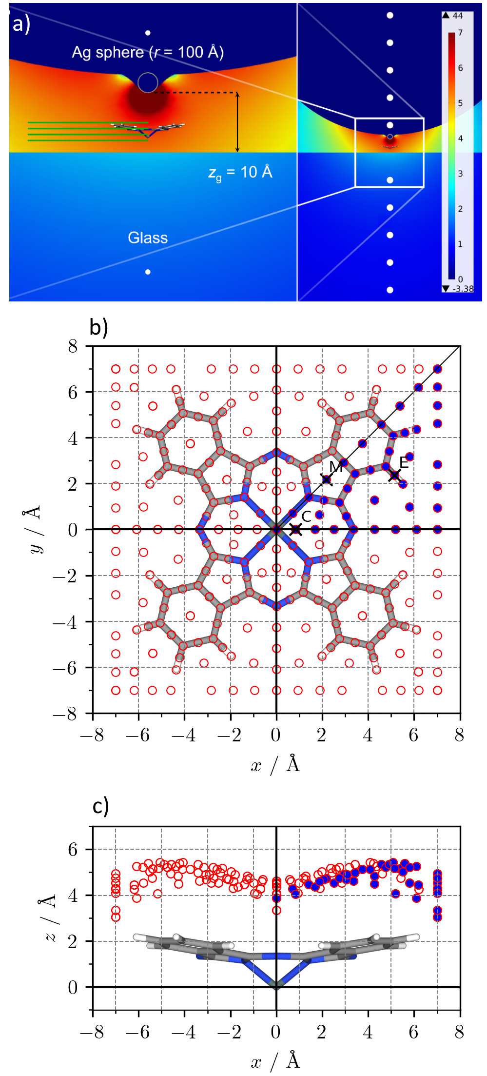
The following computational setup is based on the procedure introduced by Trautmann et al.[27] The Simulations were performed in a cubic system of size 700x700x with periodic boundary conditions (Floquet periodicity) at the side walls (- and -direction) and top and bottom walls (-direction) defined as periodic port boundaries. For modelling the field distribution near the tip, a spherical nanostructure (radius ) above a flat surface, acting as substrate (glass, ), was created. A substructure was modelled as solid of revolution from a Gaussian profile resembling a single atom that protrudes from the otherwise smooth surface, creating an atomic scale plasmonic substructure. The Gaussian profile was defined as:
| (3) |
with determining the width of the Gaussian profile and resembling the protrusion for a silver atom with an atomic radius of . The gap between the substrate and the lowest point of the nanoparticle was set to . Material settings for the silver nanoparticle were taken from Ref. [58].
The incident field, with an electric field strength of (),[59] entered the system from the bottom port with an angle of , where the incident power was obtained as:
| (4) |
with being the speed of light, vacuum permittivity, and air refractive index, respectively. The minimal tetrahedral mesh size was set to in a sphere around the nanoparticle and otherwise to reduce the computational cost.
The electric field distribution obtained by the finite element calculations was then mimicked by ten point charges - five above and five below the glass substrate at , respectively, see Fig. 1a)) (white dots). Two sets of these ten point charges were obtained to model the oscillating electric field at opposing field orientations: the positive (crest) and negative (trough) extreme values. Each set of point charges was introduced in the subsequent quantum chemical calculations employing Gaussian16[60], respectively, to mimic the field distribution in the vicinity of SnPc-Ag, i.e., at four layers of calibration points covering the investigated molecule and located 2 (90 grid points), 3 (129 grid points), 4 (140 grid points), and (151 grid points) above the glass substrate, see Fig. 1a)) (green dots). The electric field at these calibration points, modelled by these point charges, differs from the electric field obtained by the preliminary finite element simulations merely by (mean absolute deviation), while a maximum deviation of less than is obtained at the edge of the calibration layers (at ). The magnitude of the charges is scaled so that the field strength at the molecule’s position is about .
II.2 Quantum Chemical Simulations
The simulation of the full TERS experiment follows our previously published [53, 55, 54] (TD)DFT-based protocol, with the inclusion of the above mentioned point charges to complement the tip model. All quantum chemical calculations were carried out with Gaussian16[60] on the DFT or TDDFT level of theory, respectively, using the range-separated CAM-B3LYP[61] functional and 6-311+G**[62, 63] triple- basis set. For the heavy atoms (Sn, Ag) the electronic core potentials MWB46 and MWB28 and their respective basis sets[64] were used. The D3 dispersion correction with Becke-Johnson dampening was employed for all calculations.[65] The added point charges follow the movement of the tip atom in the -plane, above and below the SnPc molecule. All considered tip positions are shown in Fig. 1b) and c), the three positions that are discussed in detail are highlighted.
To elucidate the interplay of the chemical and the electromagnetic effect, in the SnPc-AgE system, two sub-systems were investigated as well. One without the field-creating point charges, SnPc-Ag, where only the chemical interaction between the Ag atom and the sample molecule are observed, and one without the Ag atom, SnPcE, that only shows the molecule’s response to the electric fields. The SnPc-Ag system, and with it the chemical effect, was discussed in-depth previously in Fiederling et al. [54].
In line with previous studies, the detection of the Raman signal is assumed to be mostly in -direction and therefore the intensity of each mode is dependent on the -component of the respective derivative of the (transition) polarizability tensor
| (5) |
For the non-resonant case, the polarizability derivatives are calculated directly by the quantum chemistry package. In the resonant case, transition polarizability derivatives are required and are calculated using the independent-mode displaced harmonic oscillator model (IMDHOM)[66]
| (6) |
Here, is the dimensionless displacement, the vertical excitation energy from the ground-state to excited-state and a damping factor describing homogeneous broadening (chosen as ), while represents the energy of the irradiating laser. The function , neglecting Franck-Condon factors, is given by:
| (7) |
III Results
In this section, we present the simulated TERS response of the full SnPc-AgE system and compare it to the responses of both sub-systems (SnPc-Ag and SnPcE) as well as to the free SnPc molecule. This allows us to separate the chemical (sub-system SnPc-Ag, in-depth discussed in Fiederling et al. [54]) from the electromagnetic effect (SnPcE), as modelled by the applied electric fields, and see how both interact with each other. First, the non-resonant response is evaluated with incident radiation at , assumed to be far away from any electronic excitations. In the second part, only the resonant response to the incident light is investigated, with its wavelength chosen according tothe predicted electronic excitations.
III.1 Non-Resonant
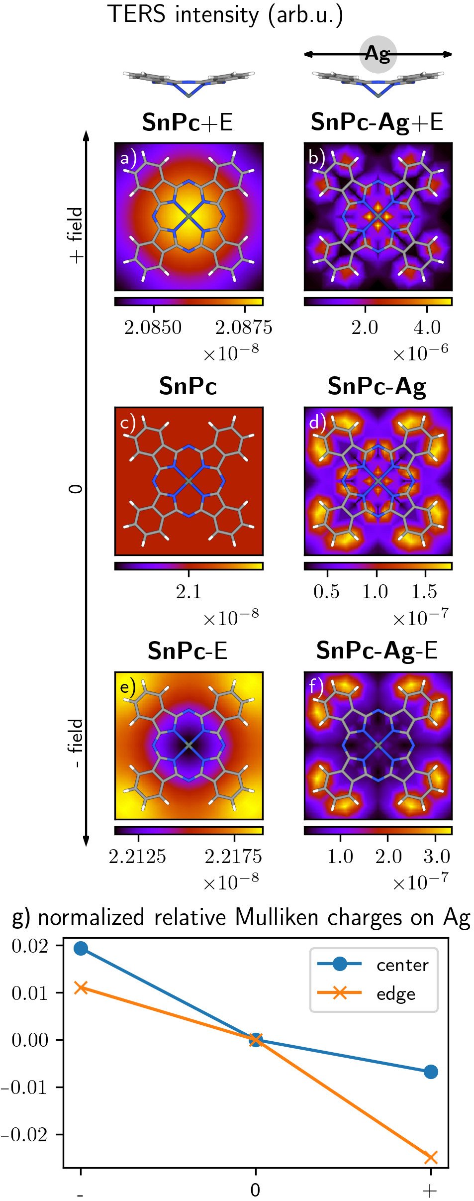
Applying the non-homogeneous electric field from the COMSOL calculations to the SnPc molecule without adding the Ag atom at the tip’s apex barely affects the molecules TERS response, as Fig. 2 a) and e) shows. The integrated intensity slightly increases for the negative field direction, while the positive direction slightly decreases the intensity. In both cases, the variation in intensity over the whole map is small, but exhibits one common feature: The central area of the molecule is brighter for the positive field direction and darker for the negative direction with respect to the map’s edges. Otherwise, there is no indication of any sub-molecular resolution. A possible explanation could be an increased electron density on the very polarizable and slightly out-of-plane outer -system in case of the negative field direction and the reverse effect for positive direction. The outermost hydrogen atoms are roughly closer to the field-creating point charges above the tip than the central Sn atom, resulting in a deviation in field strength in -direction.
For the other sub-system with only the tip atom and no external field, the response is very different. The overall intensity increases by roughly one order of magnitude and there are several equally bright, sub-molecular features. Those features correspond to three distinct regions over the molecule: the center directly around the Sn atom, the middle ’ring’ on top of the alternating C-N atoms, and the edge above the C-H bonds.
Combining both sub-systems to form the full system with the Ag atom at the tip apex and the electric field (Fig. 2 b) and f)), signal intensity generally rises and at least some of the sub-molecular structures from Fig. 2 d) are still present. In case of the positive field direction, this increase in intensity is roughly one order of magnitude with regard to the chemical sub-system and two orders of magnitude with regard to the electrostatic sub-system. All three features from the field-free chemical sub-system are still present in the map, but the ’edge’ and ’middle’ areas show less intensity than the bright ’center’ structure. This corresponds well with the Ag-free case (Fig. 2 a), where the intensity in the center of the map is slightly higher. For the negative field direction, only the ’edge’ structure remains bright, while ’middle’ and ’center’ vanish into the background. The maximum intensity increases barely by a factor of 2. Similar to the positive case, this fits the result from the respective Ag-free sub-system, where the center of the map exhibits a slightly lower intensity. In both cases, the resulting maps for the whole system reveal that both effects are interacting heavily with each other, boosting the overall degree of detail and intensity.
The different behaviour of the three features under opposite field directions can be explained by looking at the field-induced partial charge on the Ag atom. For better visualization, the charges shown are relative to the charge at the ’middle’ position in the respective sub-system, as the charge at this position is the least influenced by changing electric fields. Additionally, the charges are normalized to the respective position’s charge with no external electric field, leading to Fig. 2g). Here, it is evident that the ’center’ structure is far more sensitive to the positive field than the negative one, reflecting the bright and dark ’center’ in the respective map. Especially in the case of negative field direction, charge and intensity are barely influenced. On the ’edge’ position, the behaviour is reversed: The charge is strongly affected by the negative field, resulting in a high intensity there. The positive field does not have an equally strong effect on the tip, and the map shows a less pronounced intensity on this position.
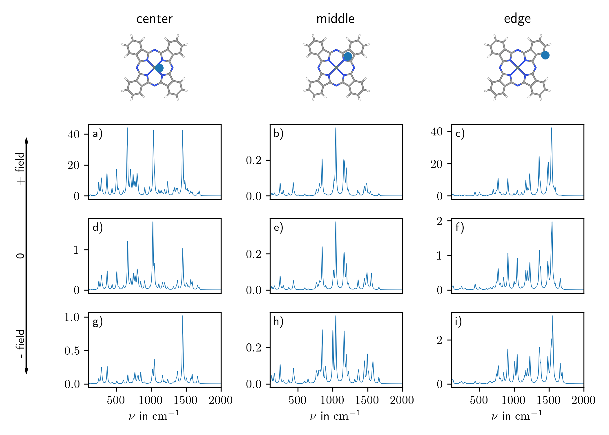
Looking at the TERS spectra (Fig. 3) for the three selected positions and possible external electric fields, it is evident that in case of the ’middle’ position (Fig. 3b), e), and h)), the field’s influence is relatively weak. The peak with the highest intensity belongs to the same normal mode in all cases, and its intensity stays rougly the same, regardless of the external field. However, small variations in the spectra are visible, such as the second-highest peak at slightly losing intensity in SnPc+E and gaining it in SnPc-E.
For the ’center’ and ’edge’ positions, the changes are much more pronounced. In the ’center’, without field, three peaks are prominent in the TERS spectra (Fig. 3d)). For the SnPc-Ag+E case, those three peaks stay relevant, though their relative intensities change. Furthermore, the overall intensity of the spectrum increases by more than one order of magnitude. In contrast, for the reversed field direction, SnPc-Ag-E, most of the spectrum stays at roughly the same intensity as without field, with two of the three prominent peaks mostly vanishing.
At the ’edge’ position, similar phenomena are observed. For the positive field direction, the overall intensity grows, especially for peaks that were already dominating the spectrum, like the one at . The negative field direction also shows a slight increase in the overall intensity in this case, mostly preserving the relative intensities across the spectrum compared to the field-free case.
III.2 Resonant
If the energy of the incident light matches that of a dipole-allowed electronic transition, the molecule’s response is no longer governed by the (non-resonant) Raman effect, but rather by the resonant one. In this case, the signal intensity is proportional to the square of the derivative of the transition polarizability, see eq. 5. Therefore, according to eq. 6, two major contributors to a strong resonant Raman response are the transition dipole moment (in -direction) of the state in resonance and its excitation energy.
Fundamentally, there are three different classes of excited states to consider here: local excitations of the SnPc molecule, charge-transfer excitations (in either direction) between the silver tip and the molecule, and local excitations on the silver tip (plasmons for larger clusters of metalic atoms). The last type of excitation will not be discussed here, as the accurate description of plasmons is not possible with the single-atom model employed for the tip herein.
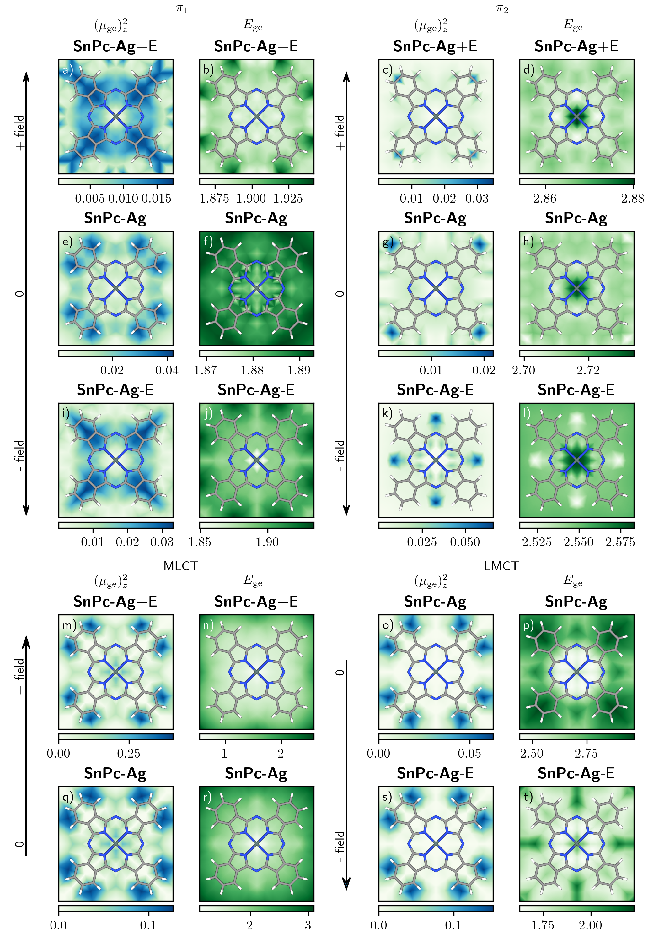
In line with previous results[54, 55], local excitations on the molecule (mostly of character here) are relatively insensitive to tip positioning and applied electric fields, both in terms of excitation energy and transition dipole moment, as Fig. 4 shows. Typically, these states are also polarized in the molecular plane, which makes them nearly invisible for detection in -direction. The SnPc molecule is not wholly planar, therefore these transitions might contribute to signal strength (and therefore sub-molecular resolution) at the slightly upwards-angled edges of the molecule, but are otherwise only of minor importance for signal intensity and resolution.
In case of SnPc-Ag, charge-transfer states between molecule and tip exist (in the observed energy window) in both directions, i.e. as metal-to-ligand charge transfer (MLCT)and ligand-to-metal charge transfer (LMCT). For SnPc-AgE, depending on the field direction, one of them gets shifted to lower energies (on average about ), while the other one is shifted significantly higher, outside the observed energy window, therefore Fig. 4 only shows maps for two CT states, respectively. In contrast to the transitions, the excitation energies are highly dependent on the tip position, regardless of the applied electric field. The field therefore influences the resolution through strong shifts in excitation energies, where mostly the regions with matching resonance show strong signals. However, the transition dipole moment shows a remarkable independence from tip-position and even somewhat from the direction of the charge transfer, while its magnitude changes with field strength. Here, the electric fields only play a role in enhancing the signal strength, and do not affect the resolution.
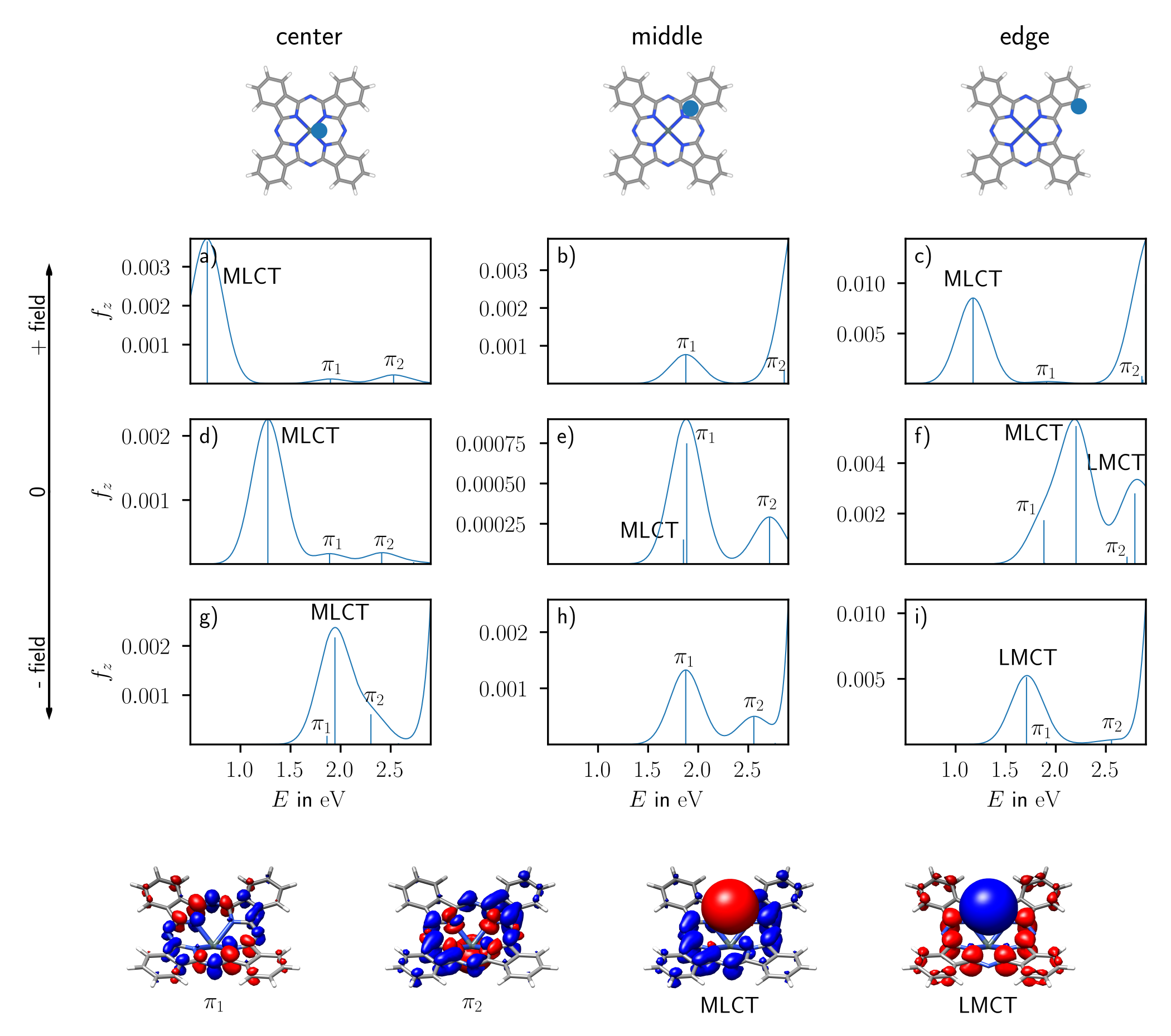
The same general behaviour of excited states can be oberved in the UV/vis spectra (Fig. 5). For the ’middle’ position (Fig. 5b), e), and h)), mostly only the two sets of near-degenerate states are accessible in the visible region. As mentioned above, they are mostly -polarized, and the transition dipole moment vector has only a small component in -direction to be visible here. The molecule-centered states are relatively unaffected by the external fields present in b) and h), both in terms of oscillator strength and excitation energy. Charge-transfer states do exist, but are dark () at this position.
At the ’center’ and ’edge’ positions, the states behave accordingly, but are overshadowed by charge-transfer states, that therefore govern the resonant regime. Already without any external fields, excitation energy and oscillator strength of these states are highly dependent on the tip’s position, as we could previously[54] show. With fields, the CT states’ oscillator strengths (and squared transition dipole moments, see Fig. 4) are increased slightly in case of SnPc-Ag-E to moderately (SnPc-Ag+E). Additionally, the excitation energies are shifted according to field and charge transfer direction. The highest peaks in the field-free case (see d) and f)) are states with electron transfer from the Ag tip to the molecule and are therefore stabilized in SnPc-Ag+E (negative charge above Ag), as the respective peaks are shifted to lower excitations energies in a) and c). Similarly, in case of SnPc-Ag-E, this charge-transfer state is shifted to higher excitation energy in g) and replaced by another state with opposite charge transfer character (i.e. from molecule to tip) in i). Due to the enormous sensitivity of the resonance Raman signal on the tip position, the applied field (direction), and excitation energy, we decided not to compare the obtained resonant TERS maps in detail.
IV Conclusion
This contribution extends our previous model of a possible TERS experiment further by incorporating inhomogeneous (static) electric fields from a plasmonic nanoparticle, advancing our understanding beyond the chemical effect. The electric fields, introduced through sets of point charges, represent examplarily the extreme values reached during the oscillation of the plasmon. Our sample molecule, tin(II) phthalocyanine (SnPc), is scanned by a single silver atom and accompanying point charges, mimicking the chemical and electromagnetic interaction with the plasmonic tip in a full quantum mechanical setup. The system’s response is compared to the same setup without either the silver atom, only showing the effect of the fields, and the SnPc-Ag system, without any field contributions. This allows us to understand both effects independently and their interaction, in particular regarding signal intensity and possible sub-molecular resolution. We described the system using DFT, TDDFT, and FEM, while registering the Raman response only in -direction; though our approach is easily generalizable to different levels of theory and other illumination-observation geometries.
In case of non-resonant conditions, we observed a slight increase in signal intensity by introducing the electric fields to the SnPc molecule, with relatively uniform change over different tip positions, only slightly highlighting either the center or the edge of the map. However, the inclusion of the silver atom at the tip’s apex introduces strong differences over the whole Raman map, hinting at a sub-molecular resolution. The combined systems exhibit the same features from the one only including the silver tip, folded together with the signal increase from the field, along with the highlighting of different features (center / edge). We rationalize this through changing partial charges at the tip atom, reacting to the different chemical environments over different parts of the molecule.
Under resonant conditions, we identify charge-transfer states between tip and molecule as the major contributors to high lateral resolution and signal intensity. The excitation energy of these states is highly dependent on tip position as well as field direction and strength. However, the transition dipole moment, an important factor for the resonance Raman intensity, is only dependent on the tip position, and therefore the chemical environment. Incorporating electric fields only increases the overall magnitude of the transition dipole moment, not its pattern.
Both non-resonant and resonant cases hint at the underlying idea that the chemical interaction between molecule and tip atom shapes the resolution, while the strong electric fields mainly increase signal intensity and function as a means to highlight certain chemical features, e.g. through choice of excitation wavelength. Nevertheless, the chemical contribution and the field effect are strongly influencing each other and should not be considered seperately.
Several additional factors could not be included in this model so far, including any chemical interaction with the substrate, as well as dynamic electric fields from the plasmon, and any sort of ’backwards’ interaction from molecule to plasmon.
acknowledgements
KF thanks Karl Michael Ziems for fruitful discussions. The authors gratefully acknowledge funding from the European Research Council (ERC) under the European’s Horizon 2020 research and innovation programme – QUEM-CHEM (grant number 772676), “Time- and space-resolved ultrafast dynamics in molecular plasmonic hybrid systems“. This work was further funded by the Deutsche Forschungsgemeinschaft (DFG, German Research Foundation) – CRC 1375 NOA (project number 398816777), project A4. All calculations were performed at the Universitätsrechenzentrum of the Friedrich Schiller University Jena.
References
- Stöckle et al. [2000] R. M. Stöckle, Y. D. Suh, V. Deckert, and R. Zenobi, “Nanoscale chemical analysis by tip-enhanced Raman spectroscopy,” Chemical Physics Letters 318, 131–136 (2000).
- Hayazawa et al. [2000] N. Hayazawa, Y. Inouye, Z. Sekkat, and S. Kawata, “Metallized tip amplification of near-field Raman scattering,” Optics Communications 183, 333–336 (2000).
- Anderson [2000] M. S. Anderson, “Locally enhanced Raman spectroscopy with an atomic force microscope,” Applied Physics Letters 76, 3130–3132 (2000).
- Zhang et al. [2013] R. Zhang, Y. Zhang, Z. C. Dong, S. Jiang, C. Zhang, L. G. Chen, L. Zhang, Y. Liao, J. Aizpurua, Y. Luo, J. L. Yang, and J. G. Hou, “Chemical mapping of a single molecule by plasmon-enhanced Raman scattering,” Nature 498, 82–86 (2013).
- Fang et al. [2014] Y. Fang, Z. Zhang, L. Chen, and M. Sun, “Near field plasmonic gradient effects on high vacuum tip-enhanced Raman spectroscopy,” Physical Chemistry Chemical Physics 17, 783–794 (2014).
- Klingsporn et al. [2014] J. M. Klingsporn, N. Jiang, E. A. Pozzi, M. D. Sonntag, D. Chulhai, T. Seideman, L. Jensen, M. C. Hersam, and R. P. V. Duyne, “Intramolecular Insight into Adsorbate–Substrate Interactions via Low-Temperature, Ultrahigh-Vacuum Tip-Enhanced Raman Spectroscopy,” Journal of the American Chemical Society 136, 3881–3887 (2014).
- Sun et al. [2014] M. Sun, Z. Zhang, L. Chen, S. Sheng, and H. Xu, “Plasmonic Gradient Effects on High Vacuum Tip-Enhanced Raman Spectroscopy,” Advanced Optical Materials 2, 74–80 (2014).
- He et al. [2019] Z. He, Z. Han, M. Kizer, R. J. Linhardt, X. Wang, A. M. Sinyukov, J. Wang, V. Deckert, A. V. Sokolov, J. Hu, and M. O. Scully, “Tip-Enhanced Raman Imaging of Single-Stranded DNA with Single Base Resolution,” Journal of the American Chemical Society 141, 753–757 (2019).
- Jiang et al. [2015] S. Jiang, Y. Zhang, R. Zhang, C. Hu, M. Liao, Y. Luo, J. Yang, Z. Dong, and J. G. Hou, “Distinguishing adjacent molecules on a surface using plasmon-enhanced Raman scattering,” Nature Nanotechnology 10, 865–869 (2015).
- Lee et al. [2019] J. Lee, K. T. Crampton, N. Tallarida, and V. A. Apkarian, “Visualizing vibrational normal modes of a single molecule with atomically confined light,” Nature 568, 78–82 (2019).
- Richard-Lacroix et al. [2017] M. Richard-Lacroix, Y. Zhang, Z. Dong, and V. Deckert, “Mastering high resolution tip-enhanced Raman spectroscopy: Towards a shift of perception,” Chemical Society Reviews 46, 3922–3944 (2017).
- Fleischmann, Hendra, and McQuillan [1974] M. Fleischmann, P. J. Hendra, and A. J. McQuillan, “Raman spectra of pyridine adsorbed at a silver electrode,” Chemical Physics Letters 26, 163–166 (1974).
- Albrecht and Creighton [1977] M. G. Albrecht and J. A. Creighton, “Anomalously intense Raman spectra of pyridine at a silver electrode,” Journal of the American Chemical Society 99, 5215–5217 (1977).
- Jeanmaire and Van Duyne [1977] D. L. Jeanmaire and R. P. Van Duyne, “Surface raman spectroelectrochemistry: Part I. Heterocyclic, aromatic, and aliphatic amines adsorbed on the anodized silver electrode,” Journal of Electroanalytical Chemistry and Interfacial Electrochemistry 84, 1–20 (1977).
- Langer et al. [2020] J. Langer, D. Jimenez de Aberasturi, J. Aizpurua, R. A. Alvarez-Puebla, B. Auguié, J. J. Baumberg, G. C. Bazan, S. E. J. Bell, A. Boisen, A. G. Brolo, J. Choo, D. Cialla-May, V. Deckert, L. Fabris, K. Faulds, F. J. García de Abajo, R. Goodacre, D. Graham, A. J. Haes, C. L. Haynes, C. Huck, T. Itoh, M. Käll, J. Kneipp, N. A. Kotov, H. Kuang, E. C. Le Ru, H. K. Lee, J.-F. Li, X. Y. Ling, S. A. Maier, T. Mayerhöfer, M. Moskovits, K. Murakoshi, J.-M. Nam, S. Nie, Y. Ozaki, I. Pastoriza-Santos, J. Perez-Juste, J. Popp, A. Pucci, S. Reich, B. Ren, G. C. Schatz, T. Shegai, S. Schlücker, L.-L. Tay, K. G. Thomas, Z.-Q. Tian, R. P. Van Duyne, T. Vo-Dinh, Y. Wang, K. A. Willets, C. Xu, H. Xu, Y. Xu, Y. S. Yamamoto, B. Zhao, and L. M. Liz-Marzán, “Present and Future of Surface-Enhanced Raman Scattering,” ACS Nano 14, 28–117 (2020).
- Jiang et al. [2012] N. Jiang, E. T. Foley, J. M. Klingsporn, M. D. Sonntag, N. A. Valley, J. A. Dieringer, T. Seideman, G. C. Schatz, M. C. Hersam, and R. P. Van Duyne, “Observation of Multiple Vibrational Modes in Ultrahigh Vacuum Tip-Enhanced Raman Spectroscopy Combined with Molecular-Resolution Scanning Tunneling Microscopy,” Nano Letters 12, 5061–5067 (2012).
- Pettinger et al. [2004] B. Pettinger, B. Ren, G. Picardi, R. Schuster, and G. Ertl, “Nanoscale Probing of Adsorbed Species by Tip-Enhanced Raman Spectroscopy,” Physical Review Letters 92, 096101 (2004).
- Corni and Tomasi [2001a] S. Corni and J. Tomasi, “Theoretical evaluation of Raman spectra and enhancement factors for a molecule adsorbed on a complex-shaped metal particle,” Chemical Physics Letters 342, 135–140 (2001a).
- Corni and Tomasi [2001b] S. Corni and J. Tomasi, “Surface enhanced Raman scattering from a single molecule adsorbed on a metal particle aggregate: A theoretical study,” The Journal of Chemical Physics 116, 1156–1164 (2001b).
- Chulhai and Jensen [2013] D. V. Chulhai and L. Jensen, “Determining Molecular Orientation With Surface-Enhanced Raman Scattering Using Inhomogenous Electric Fields,” The Journal of Physical Chemistry C 117, 19622–19631 (2013).
- Chiang et al. [2015] N. Chiang, N. Jiang, D. V. Chulhai, E. A. Pozzi, M. C. Hersam, L. Jensen, T. Seideman, and R. P. Van Duyne, “Molecular-Resolution Interrogation of a Porphyrin Monolayer by Ultrahigh Vacuum Tip-Enhanced Raman and Fluorescence Spectroscopy,” Nano Letters 15, 4114–4120 (2015).
- Zhang, Chen, and Li [2015] C. Zhang, B.-Q. Chen, and Z.-Y. Li, “Optical Origin of Subnanometer Resolution in Tip-Enhanced Raman Mapping,” The Journal of Physical Chemistry C 119, 11858–11871 (2015).
- Morton, Silverstein, and Jensen [2011] S. M. Morton, D. W. Silverstein, and L. Jensen, “Theoretical Studies of Plasmonics using Electronic Structure Methods,” Chemical Reviews 111, 3962–3994 (2011).
- Thomas et al. [2013] M. Thomas, S. Mühlig, T. Deckert-Gaudig, C. Rockstuhl, V. Deckert, and P. Marquetand, “Distinguishing chemical and electromagnetic enhancement in surface-enhanced Raman spectra: The case of para-nitrothiophenol,” Journal of Raman Spectroscopy 44, 1497–1505 (2013).
- Zhang et al. [2014] P. Zhang, J. Feist, A. Rubio, P. García-González, and F. J. García-Vidal, “Ab initio nanoplasmonics: The impact of atomic structure,” Physical Review B 90, 161407 (2014).
- Benz et al. [2016] F. Benz, M. K. Schmidt, A. Dreismann, R. Chikkaraddy, Y. Zhang, A. Demetriadou, C. Carnegie, H. Ohadi, B. de Nijs, R. Esteban, J. Aizpurua, and J. J. Baumberg, “Single-molecule optomechanics in “picocavities”,” Science 354, 726–729 (2016).
- Trautmann et al. [2016] S. Trautmann, J. Aizpurua, I. Götz, A. Undisz, J. Dellith, H. Schneidewind, M. Rettenmayr, and V. Deckert, “A classical description of subnanometer resolution by atomic features in metallic structures,” Nanoscale 9, 391–401 (2016).
- Chen and Jensen [2018] X. Chen and L. Jensen, “Morphology dependent near-field response in atomistic plasmonic nanocavities,” Nanoscale 10, 11410–11417 (2018).
- Urbieta et al. [2018] M. Urbieta, M. Barbry, Y. Zhang, P. Koval, D. Sánchez-Portal, N. Zabala, and J. Aizpurua, “Atomic-Scale Lightning Rod Effect in Plasmonic Picocavities: A Classical View to a Quantum Effect,” ACS Nano 12, 585–595 (2018).
- Baumberg et al. [2019] J. J. Baumberg, J. Aizpurua, M. H. Mikkelsen, and D. R. Smith, “Extreme nanophotonics from ultrathin metallic gaps,” Nature Materials 18, 668–678 (2019).
- Zhao, Jensen, and Schatz [2006] Zhao, L. Jensen, and G. C. Schatz, “Pyridine-Ag20 Cluster: A Model System for Studying Surface-Enhanced Raman Scattering,” Journal of the American Chemical Society 128, 2911–2919 (2006).
- Jensen, Zhao, and Schatz [2007] L. Jensen, L. L. Zhao, and G. C. Schatz, “Size-Dependence of the Enhanced Raman Scattering of Pyridine Adsorbed on Agn (n = 2-8, 20) Clusters,” The Journal of Physical Chemistry C 111, 4756–4764 (2007).
- Jensen, Aikens, and Schatz [2008] L. Jensen, C. M. Aikens, and G. C. Schatz, “Electronic structure methods for studying surface-enhanced Raman scattering,” Chemical Society Reviews 37, 1061–1073 (2008).
- Liu et al. [2009] S. Liu, X. Zhao, Y. Li, M. Chen, and M. Sun, “DFT study of adsorption site effect on surface-enhanced Raman scattering of neutral and charged pyridine–Ag4 complexes,” Spectrochimica Acta Part A: Molecular and Biomolecular Spectroscopy 73, 382–387 (2009).
- Valley et al. [2013] N. Valley, N. Greeneltch, R. P. Van Duyne, and G. C. Schatz, “A Look at the Origin and Magnitude of the Chemical Contribution to the Enhancement Mechanism of Surface-Enhanced Raman Spectroscopy (SERS): Theory and Experiment,” The Journal of Physical Chemistry Letters 4, 2599–2604 (2013).
- Latorre, Guthmuller, and Marquetand [2015] F. Latorre, J. Guthmuller, and P. Marquetand, “A spectroscopic study of the cis/trans-isomers of penta-2,4-dienoic acid attached to gold nanoclusters,” Physical Chemistry Chemical Physics 17, 7648–7658 (2015).
- Barbry et al. [2015] M. Barbry, P. Koval, F. Marchesin, R. Esteban, A. G. Borisov, J. Aizpurua, and D. Sánchez-Portal, “Atomistic Near-Field Nanoplasmonics: Reaching Atomic-Scale Resolution in Nanooptics,” Nano Letters 15, 3410–3419 (2015).
- Schmidt et al. [2016] M. K. Schmidt, R. Esteban, A. González-Tudela, G. Giedke, and J. Aizpurua, “Quantum Mechanical Description of Raman Scattering from Molecules in Plasmonic Cavities,” ACS Nano 10, 6291–6298 (2016).
- Zhang, Dong, and Aizpurua [2021] Y. Zhang, Z.-C. Dong, and J. Aizpurua, “Theoretical treatment of single-molecule scanning Raman picoscopy in strongly inhomogeneous near fields,” Journal of Raman Spectroscopy 52, 296–309 (2021).
- Payton et al. [2012] J. L. Payton, S. M. Morton, J. E. Moore, and L. Jensen, “A discrete interaction model/quantum mechanical method for simulating surface-enhanced Raman spectroscopy,” The Journal of Chemical Physics 136, 214103 (2012).
- Payton et al. [2014] J. L. Payton, S. M. Morton, J. E. Moore, and L. Jensen, “A Hybrid Atomistic Electrodynamics–Quantum Mechanical Approach for Simulating Surface-Enhanced Raman Scattering,” Accounts of Chemical Research 47, 88–99 (2014).
- Hu, Chulhai, and Jensen [2016] Z. Hu, D. V. Chulhai, and L. Jensen, “Simulating Surface-Enhanced Hyper-Raman Scattering Using Atomistic Electrodynamics-Quantum Mechanical Models,” Journal of Chemical Theory and Computation 12, 5968–5978 (2016).
- Liu, Chulhai, and Jensen [2017] P. Liu, D. V. Chulhai, and L. Jensen, “Single-Molecule Imaging Using Atomistic Near-Field Tip-Enhanced Raman Spectroscopy,” ACS Nano 11, 5094–5102 (2017).
- Chen et al. [2019] X. Chen, P. Liu, Z. Hu, and L. Jensen, “High-resolution tip-enhanced Raman scattering probes sub-molecular density changes,” Nature Communications 10, 2567 (2019).
- Hao and Schatz [2003] E. Hao and G. C. Schatz, “Electromagnetic fields around silver nanoparticles and dimers,” The Journal of Chemical Physics 120, 357–366 (2003).
- Zou, Janel, and Schatz [2004] S. Zou, N. Janel, and G. C. Schatz, “Silver nanoparticle array structures that produce remarkably narrow plasmon lineshapes,” The Journal of Chemical Physics 120, 10871–10875 (2004).
- Gieseking, Ratner, and Schatz [2016] R. L. Gieseking, M. A. Ratner, and G. C. Schatz, “Semiempirical Modeling of Ag Nanoclusters: New Parameters for Optical Property Studies Enable Determination of Double Excitation Contributions to Plasmonic Excitation,” The Journal of Physical Chemistry A 120, 4542–4549 (2016).
- Ding et al. [2018] W. Ding, L.-Y. Hsu, C. W. Heaps, and G. C. Schatz, “Plasmon-Coupled Resonance Energy Transfer II: Exploring the Peaks and Dips in the Electromagnetic Coupling Factor,” The Journal of Physical Chemistry C 122, 22650–22659 (2018).
- Kluender et al. [2021] E. J. Kluender, M. R. Bourgeois, C. R. Cherqui, G. C. Schatz, and C. A. Mirkin, “Multimetallic Nanoparticles on Mirrors for SERS Detection,” The Journal of Physical Chemistry C 125, 12784–12791 (2021).
- Morton and Jensen [2010] S. M. Morton and L. Jensen, “A discrete interaction model/quantum mechanical method for describing response properties of molecules adsorbed on metal nanoparticles,” The Journal of Chemical Physics 133, 074103 (2010).
- Morton and Jensen [2011] S. M. Morton and L. Jensen, “A discrete interaction model/quantum mechanical method to describe the interaction of metal nanoparticles and molecular absorption,” The Journal of Chemical Physics 135, 134103 (2011).
- Zhao et al. [2008] J. Zhao, A. O. Pinchuk, J. M. McMahon, S. Li, L. K. Ausman, A. L. Atkinson, and G. C. Schatz, “Methods for Describing the Electromagnetic Properties of Silver and Gold Nanoparticles,” Accounts of Chemical Research 41, 1710–1720 (2008).
- Latorre et al. [2016] F. Latorre, S. Kupfer, T. Bocklitz, D. Kinzel, S. Trautmann, S. Gräfe, and V. Deckert, “Spatial resolution of tip-enhanced Raman spectroscopy – DFT assessment of the chemical effect,” Nanoscale 8, 10229–10239 (2016).
- Fiederling et al. [2020] K. Fiederling, M. Abasifard, M. Richter, V. Deckert, S. Gräfe, and S. Kupfer, “The chemical effect goes resonant – a full quantum mechanical approach on TERS,” Nanoscale 12, 6346–6359 (2020).
- Fiederling, Kupfer, and Gräfe [2021] K. Fiederling, S. Kupfer, and S. Gräfe, “Are charged tips driving TERS-resolution? A full quantum chemical approach,” The Journal of Chemical Physics 154, 034106 (2021).
- Rodriguez et al. [2021] R. D. Rodriguez, C. J. Villagómez, A. Khodadadi, S. Kupfer, A. Averkiev, L. Dedelaite, F. Tang, M. Y. Khaywah, V. Kolchuzhin, A. Ramanavicius, P.-M. Adam, S. Gräfe, and E. Sheremet, “Chemical Enhancement vs Molecule–Substrate Geometry in Plasmon-Enhanced Spectroscopy,” ACS Photonics 8, 2243–2255 (2021).
- [57] “COMSOL Multiphysics,” COMSOL AB.
- Johnson and Christy [1972] P. B. Johnson and R. W. Christy, “Optical Constants of the Noble Metals,” Physical Review B 6, 4370–4379 (1972).
- Sakko, Rossi, and Nieminen [2014] A. Sakko, T. P. Rossi, and R. M. Nieminen, “Dynamical coupling of plasmons and molecular excitations by hybrid quantum/classical calculations: Time-domain approach,” Journal of Physics. Condensed Matter: An Institute of Physics Journal 26, 315013 (2014).
- Frisch et al. [2016] M. J. Frisch, G. W. Trucks, H. B. Schlegel, G. E. Scuseria, M. A. Robb, J. R. Cheeseman, G. Scalmani, V. Barone, G. A. Petersson, H. Nakatsuji, X. Li, M. Caricato, A. V. Marenich, J. Bloino, B. G. Janesko, R. Gomperts, B. Mennucci, H. P. Hratchian, J. V. Ortiz, A. F. Izmaylov, J. L. Sonnenberg, D. Williams-Young, F. Ding, F. Lipparini, F. Egidi, J. Goings, B. Peng, A. Petrone, T. Henderson, D. Ranasinghe, V. G. Zakrzewski, J. Gao, N. Rega, G. Zheng, W. Liang, M. Hada, M. Ehara, K. Toyota, R. Fukuda, J. Hasegawa, M. Ishida, T. Nakajima, Y. Honda, O. Kitao, H. Nakai, T. Vreven, K. Throssell, J. A. Montgomery, Jr., J. E. Peralta, F. Ogliaro, M. J. Bearpark, J. J. Heyd, E. N. Brothers, K. N. Kudin, V. N. Staroverov, T. A. Keith, R. Kobayashi, J. Normand, K. Raghavachari, A. P. Rendell, J. C. Burant, S. S. Iyengar, J. Tomasi, M. Cossi, J. M. Millam, M. Klene, C. Adamo, R. Cammi, J. W. Ochterski, R. L. Martin, K. Morokuma, O. Farkas, J. B. Foresman, and D. J. Fox, “Gaussian 16 Revision B.01,” (2016).
- Yanai, Tew, and Handy [2004] T. Yanai, D. P. Tew, and N. C. Handy, “A new hybrid exchange–correlation functional using the Coulomb-attenuating method (CAM-B3LYP),” Chemical Physics Letters 393, 51–57 (2004).
- Krishnan et al. [1980] R. Krishnan, J. S. Binkley, R. Seeger, and J. A. Pople, “Self-consistent molecular orbital methods. XX. A basis set for correlated wave functions,” The Journal of Chemical Physics 72, 650–654 (1980).
- Clark et al. [1983] T. Clark, J. Chandrasekhar, G. W. Spitznagel, and P. V. R. Schleyer, “Efficient diffuse function-augmented basis sets for anion calculations. III. The 3-21+G basis set for first-row elements, Li–F,” Journal of Computational Chemistry 4, 294–301 (1983).
- Andrae et al. [1990] D. Andrae, U. Häußermann, M. Dolg, H. Stoll, and H. Preuß, “Energy-adjusted ab initio pseudopotentials for the second and third row transition elements,” Theoretica chimica acta 77, 123–141 (1990).
- Grimme, Ehrlich, and Goerigk [2011] S. Grimme, S. Ehrlich, and L. Goerigk, “Effect of the damping function in dispersion corrected density functional theory,” Journal of Computational Chemistry 32, 1456–1465 (2011).
- Guthmuller [2016] J. Guthmuller, “Comparison of simplified sum-over-state expressions to calculate resonance Raman intensities including Franck-Condon and Herzberg-Teller effects,” The Journal of Chemical Physics 144, 064106 (2016).