Quantum metrology of low frequency electromagnetic modes with frequency upconverters
Abstract
We describe the RF Quantum Upconverter (RQU) and describe its application to quantum metrology of electromagnetic modes between dc and the Very High Frequency band (VHF) (300MHz). The RQU uses a Josephson interferometer made up of superconducting loops and Josephson junctions to implement a parametric interaction between a low-frequency electromagnetic mode (between dc and VHF) and a mode in the microwave C Band ( 5GHz), analogous to the radiation pressure interaction between electromagnetic and mechanical modes in cavity optomechanics. The RQU can operate as a quantum-limited op-amp, or use protocols from optomechanics to implement non-classical measurement protocols equivalent to those used in cavity optomechanics, including back-action evading (BAE) measurements, sideband cooling, and two-mode squeezing. These protocols enable experiments using dc–VHF electromagnetic modes as quantum sensors.
I Introduction
The field of Circuit Quantum Electrodynamics (Circuit QED) has made impressive strides in harnessing the quantum-mechanical properties of superconducting circuits operating in the microwave frequency regime (typically several GHz) Blais2007 . The techniques of Circuit QED have advanced to the point that detecting Johnson2010 ; chen2011 and coherently manipulating nakamura1999 a single microwave quantum are routine operations, and individual control over arrays of dozens of interacting quantum circuits is possible arute2019 . Much of this progress has been driven by the desire to build a universal quantum computer capable of performing calculations that would be impractical on any classical computer.
The techniques of Circuit QED do not extend directly to lower frequencies, however. Recently, there has been growing interest in adapting quantum metrology techniques to lower frequency electromagnetic modes, typically at frequencies between dc and the Very High Frequency (VHF) band below 300 MHz. Quantum metrology of low-frequency modes could offer a “quantum speedup” over classical sensors, enabling experiments that would otherwise be impractical.
For example, searches for sub-eV axion or axion-like dark matter aim to detect or rule out yoctowatt-scale electromagnetic signals over many decades in frequency, spanning from 100Hz to 300MHz Chaudhuri2015 ; phipps2020 ; Ouellet2019 ; crisosto2020 ; Garcon2018 ; Nguyen2019 . Circuits in this frequency range can carry useful information at frequencies significantly detuned from their resonant frequency, where thermal fluctuations are suppressed to below the level of a single photon per second per Hz of bandwidth chaudhuri2018 ; chaudhuri2019 . This off-resonant information can only be accessed by readout techniques operating beyond the Standard Quantum Limit (SQL). In this case, improving the readout performance does not substantially improve the signal to noise ratio (SNR) on resonance (which is limited by thermal fluctuations), but it allows constant SNR to be maintained over a much broader bandwidth, dramatically increasing the axion search rate.
In this work, we describe the RF Quantum Upconverter (RQU), a flexible device that mimics the radiation-pressure interaction in cavity optomechanics, but replaces the low-frequency mechanical mode with a low-frequency electromagnetic mode. The RQU uses the nonlinearity of Josephson junctions to upconvert signals from the sensor frequency to microwave frequencies. This upconversion paradigm allows the RQU to take advantage of several mature microwave Circuit QED technologies, including high coherence microwave resonators Reagor2016 , Josephson Parametric Amplifiers (JPAs) Roy2016 , and microwave squeezers CastellanosBeltran2008 , while extending the frequency range of quantum measurement techniques to lower frequencies.
In this work we show that the RQU implements an analogous interaction to that of cavity optomechanics. We show that this interaction allows the RQU to act as a quantum-limited op-amp with tunable noise impedance. When operated in this mode, the RQU has advantages over a dc SQUID. The noise impedance of a dc SQUID is intrinsically linked to (the self-inductance of its input coil), which can limit energy transfer in untuned circuits. In contrast, the noise impedance of an RQU can also be tuned by varying its microwave drive power without changing . Thus, in principle, the RQU can achieve an “energy sensitivity” significantly below when coupled to an untuned input inductor, where is the imprecision current noise referred to the input coil (and quantum backaction is not significant). Such performance is not possible with a dc SQUID in which is linked to Voss1981 . Finally, the RQU can operate as a phase-sensitive amplifier. This mode corresponds to backaction-evading techniques from optomechanics Clerk2008 .
II Analogy between cavity optomechanics and op-amp mode amplification
II.1 Upconverter Hamiltonian
In order to evaluate the RQU as a tool for quantum metrology, we use a model in which both the RQU and its input circuit are quantized, with an interaction Hamiltonian that couples the modes. This Hamiltonian is exactly analogous to that of cavity optomechanics, but the mechanical mode is replaced with an electromagnetic mode, referred to in this section as the “low-frequency mode” to distinguish it from the microwave mode.
Cavity optomechanics treats two bosonic modes at different frequencies: an electromagnetic mode at and a mechanical mode at , with Aspelmeyer2014 . The position operator of the mechanical mode represents the position of a movable mirror that forms one end of the optical cavity. The modes are quantized with ladder operators and , , respectively. The uncoupled Hamiltonian is:
| (1) |
In terms of ladder operators, the mirror position is given by:
| (2) |
where is the magnitude of the zero-point position fluctuations. The frequency of photons occupying the optical mode depends on the position of the movable mirror, leading to the parametric optomechanical interaction between the two modes:
| (3) |
where is the optomechanical coupling strength, describing the frequency shift of an optical photon due to the position of the mechanical oscillator.
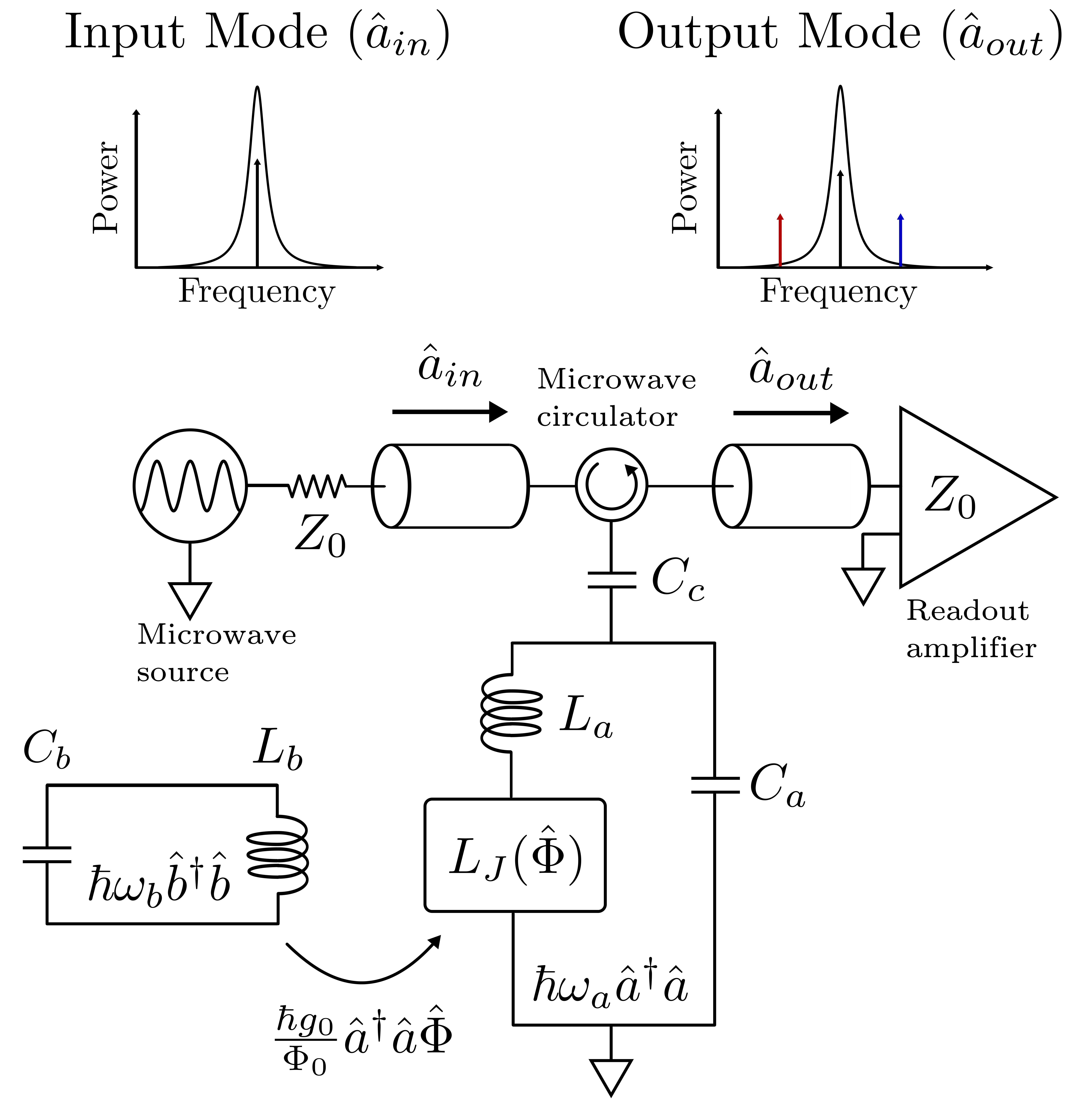
An optomechanical-style coupling can be realized in superconducting circuits by including a Josephson interferometer whose inductance depends on the flux in the low-frequency mode. The flux causes the microwave resonance frequency to vary, just as position shifts of the moving mirror cause the optical frequency to vary in the optomechanical setup. Figure 1 shows a circuit model of such an upconverter with the associated ladder operators.
The uncoupled Hamiltonian is exactly the one in equation 1, with the phonon ladder operators replaced by photon operators for the low-frequency mode. The microwave and low-frequency modes represented by harmonic oscillators with frequencies:
| (4) | |||
| (5) |
The low frequency mode is inductively coupled to the Josephson interferometer, such that the flux threading the low-frequency resonator also threads the Josephson interferometer. In this way, the tunability of will mediate a parametric interaction, with playing the role of the position operator . Analogously to equation 2, we have:
| (6) |
where is magnitude of the zero point flux fluctuations: .
In order to treat the interaction between the modes, we include the perturbation of due to the sensor flux. For small fluxes satisfying , we Taylor expand the microwave frequency to first order in the sensor flux, to calculate the shift of the microwave resonance frequency due to flux in the sensor:
| (7) |
The frequency shift per unit applied flux describes the strength of the interaction between the modes, with:
| (8) |
The two derivatives on the RHS of equation 8 depend on the particular design of the interferometer and low frequency resonator, which we can calculate for a given interferometer design using circuit techniques. We can write the upconverter interaction Hamiltonian in equation 7 in a form analogous to the radiation pressure interaction in equation 3:
| (9) |
Without loss of generality, we choose the the sign of increasing to yield the minus sign in equation 7. Because it involves products of three ladder operators, this interaction describes three-wave mixing. The strength of the optomechanical-style coupling is given by:
| (10) |
II.2 Input-Output Model
In order to operate the RQU, we need to control and detect the state of the microwave resonator, which will allow us to infer the state of the low-frequency resonator. The Hamiltonian in equation 7 only accounts for the interaction between the two modes, and does not include external couplings or dissipation. In order to detect and control the state of the microwave resonator, we couple the microwave resonator to a waveguide that allows microwave photons to escape the cavity for amplification and demodulation. Finally, the model must also account for the effects of internal dissipation in both the RF and microwave modes.
The total Hamiltonian, accounting for the external coupling, dissipation, and the microwave drive is given by:
| (11) |
where describes the dynamics of the isolated RQU system (microwave resonator plus low-frequency resonator, and their interaction), as described in equations 1 and 7. captures the effects of loss in the microwave resonator, which is dominated by loss to the strongly coupled readout port. describes loss to internal dissipation in the low-frequency resonator. Finally, accounts for the energy supplied by the external drive tones which probe the RQU state.
The traveling-wave modes used in this section are shown in figure 1: the microwave resonator is coupled to an “input” mode and an “output” mode which are used to drive and detect the state of the microwave resonator. The field circulating within the microwave resonator, , is referred to as the intra-cavity field. A circulator prevents leftward-propagating modes from interacting with the RQU, so we ignore them. The internal dissipation in the low-frequency resonator is modeled as arising from a semi-infinite transmission line of characteristic impedance . The incident and reflected modes on this transmission line are and , respectively.
The noise fluctuations in these input and output modes can be analyzed using standard input-output theory walls2008 , following a treatment similar to Section IIIB of Aspelmeyer2014 . The Heisenburg-Langevin equations of motion for the system are:
| (12) | |||
| (13) |
where is the decay rate of the circulating power in the microwave resonator, and is the decay rate in the low-frequency resonator. Dots indicate time derivatives. describes three-wave mixing, so equations 12 and 13 are nonlinear. Our present analysis will focus on the regime where we can linearize , although experiments in the highly nonlinear regime (when the single-photon interaction rate exceeds the microwave loss rate ) may prove interesting. To linearize, we write the microwave ladder operators as a sum of a classical amplitude and small quantum fluctuations:
| (14) | |||
| (15) | |||
| (16) |
Here, represents the average photon number circulating in the microwave resonator due to the drive. The drive has an amplitude (in units of photons/second). Likewise, the average photon flux propagating towards the microwave amplifier is given by . The boundary condition relating the output, input, and intra-cavity fields is:
| (17) |
We operate the upconverter in the regime of strong microwave drives, such that . Inserting expression 14 into the interaction Hamiltonian 7 yields:
| (18) |
The first term represents a constant flux offset applied to the low-frequency resonator, and can be ignored. The second and third terms represent mixing between the coherent microwave amplitudes and and the quantum noise terms and . The last term represents the interaction of the quantum noise with itself, and since it is smaller than the second and third terms by a factor of , we ignore it. Thus, the relevant portions of the interaction Hamiltonian are:
| (19) |
Since is a classical value rather than an operator, this interaction now describes an effective two-wave interaction with a tunable strength set by , rather than the three-wave interaction described by equation 7. Hence, we refer to it as the linearized interaction.
In order for to have a non-zero value in the steady state, external energy must be supplied to the microwave resonator via a driving term. A monotonic, coherent drive tone applied via the readout waveguide induces the drive Hamiltonian:
| (20) |
where represents the (classical) amplitude of the coherent voltage drive applied to the microwave resonator via the input transmission line. We apply the unitary transformation:
| (21) |
to move to a frame rotating at the drive frequency. , where is the angular velocity of the rotating frame. In this frame, the Heisenberg-Langevin equation of motion for reads:
| (22) |
where .
We begin by solving for the steady-state amplitude using the classical portion of the equation of motion 22, neglecting terms of order and with no flux applied from the sensor: . We find:
| (23) |
We can insert this steady state classical amplitude into equations 13 and 22 in order to describe the linearized dynamics of the coupled modes in the frequency domain. After neglecting DC terms and small terms of order , we find:
| (24) |
for the intra-cavity field, and
| (25) |
for the low-frequency mode.
Equations 24 and 25 fully describe the dynamics of the RQU in the linearized regime, and can be used to calculate the behavior of the coupled modes in a variety of regimes. The quantum metrology techniques in the following sections arise from special cases of these linearized dynamics where the detuning takes on the specific values or a superposition of drive tones at .
II.3 Op-amp Analogy
When the RQU is driven by a single microwave tone, it functions as an op-amp mode electromagnetic amplifier: it maps the flux variable of the low-frequency circuit onto the microwave output mode . The upconversion process adds noise as required by the Standard Quantum Limit on amplification, and in this section we show that the RQU can achieve readout at the SQL Clerk2010 . In this readout protocol, the microwave readout tone is resonant, and the low frequency signal appears in as symmetric sidebands due to the phase modulation of the reflected microwave signal.
In order to evaluate the total noise added in the upconversion process, we calculate fluctuations in the output mode when the upconverter is resonantly driven (). We use the boundary condition in equation 17 to eliminate the intra-cavity field in equation 24, yielding the equation of motion governing the small quantum fluctuations of the input and output microwave modes, and the low frequency mode:
| (26) |
The first term on the RHS of equation 26 represents the fluctuations in the input mode, which are reflected from the microwave resonator with a phase shift, but no change in amplitude. These fluctuations carry no information about the state of the low-frequency resonator, and cause uncertainty in , referred to as imprecision noise. The second term carries information about the state of the low-frequency resonator encoded in sidebands at (in the lab frame).
The other irreducible noise source arises from fluctuations in the intra-cavity field which perturb the state of the low-frequency resonator. Inserting the steady state solution for the intra-cavity field into equation 13 and focusing on the backaction terms yields an equation of motion for the low-frequency mode:
| (27) |
where (without loss of generality) we have set the phase of so that is real. Equation 27 captures the effects of microwave fluctuations that perturb the state of the low-frequency resonator, including backaction due to fluctuations in the microwave field (proportional to and ) and thermal and quantum fluctuations associated with the internal dissipation in the low-frequency resonator (proportional to ). Together, equations 26 and 27 describe the two irreducible noise sources in the upconversion process. Since the RQU is functioning as an op-amp, it is more convenient to describe the noise in the upconversion process directly in terms of the voltages and currents in the low-frequency resonator.
We take the limit of low frequencies . The total output signal at the follow-on microwave amplifier is given by equation 16. In order to recover the flux signal, we noiselessly amplify (with a degenerate JPA) and demodulate using a reference tone at , measuring the microwave phase quadrature :
| (28) |
The imprecision fluctuations can be referred back to input currents with equation 28, yielding:
| (29) |
where is the effective mutual inductance relating the input flux signal to , the current flowing through .
Using the backaction terms in equation 27, we can write the perturbation of the low-frequency current due to backaction. We find:
| (30) |
where is approximately the admittance of the low-frequency resonator at its positive and negative resonance frequencies:
| (31) |
The approximation in equation 31 holds for frequencies near the resonance frequencies . In order to evaluate the effect of backaction at frequencies very detuned from the resonance frequency, the rotating wave approximation implicit in the derivation of equation 13 would have to be dropped. The backaction voltage arises from the fluctuation terms and , and is given by:
| (32) |
Equations 32 and 29 show that backaction and imprecision noise contributions arise from the input quadratures and , respectively. If the input is prepared in a coherent state without additional noise and the output mode is detected without adding noise (e.g. if , are sourced from a cold resistor, and a noiseless, phase-sensitive JPA detects ), the fluctuations of these mode quadratures are described by the (symmetrized) noise spectral densities:
| (33) | |||
| (34) | |||
| (35) |
In other words, the quadratures have uncorrelated fluctuations with a total amplitude corresponding to a single quantum. We can now evaluate the imprecision, backaction spectral densities:
| (37) | |||
| (38) | |||
| (39) |
These spectral densities describe an op-amp mode amplifier operating at the Standard Quantum Limit. The noise impedance of this amplifier is tunable without changing the geometry or input inductance of the device, simply by changing the microwave amplitude . The total noise added by such an amplifier is the sum of these three contributions, with the op-amp achieving a total added current noise of:
| (40) |
where is the sum of the positive- and negative-frequency components of the admittance On resonance at , the admittance is purely real: . Using also the fact that , we can simplify the total noise to:
| (41) |
where is the noise temperature, which is a function of the frequency, evaluated on resonance at . Note that the densities in equations 37 and 38 have different scalings with respect to the microwave drive power . Thus, for the simplified case of optimizing the added noise on resonance, with , we find that the real, on-resonance input circuit resistance (the “noise impedance”) that optimizes the noise temperature is
| (42) |
So, the noise resistance of the RQU can be tuned by changing the pump power , without changing the input inductance.
The noise temperature is optimized when . We find the optimal power level is given by:
| (43) |
with an overall noise temperature of:
| (44) |
This corresponds to an op-amp mode amplifier operating at the SQL.
III Measuring untuned input circuits with upconversion
In some applications, especially at low frequencies, resonant input circuits are not practical. Instead, a flux signal is measured in an untuned inductive load such as a magnetometer coil. The sensitivity of this readout is often quantified by its imprecision “energy sensitivity,” which expresses the smallest current signal that can be detected above the imprecision noise for a given inductance Voss1981 . In the case of an untuned circuit, the impedance of the input circuit is so high that backaction noise is insignificant.
We can express the energy sensitivity of an upconverter operated with an untuned input circuit as:
| (45) |
where is the self inductance of the input coil which couples flux from the low-frequency circuit into the interferometer. The imprecision energy sensitivity can be expressed as a multiple of . The details of the operation of dc SQUIDs limits their imprecision energy sensitivity to (see for example koch1981 ), but we emphasize that this is not a standard quantum limit. It is nonetheless the appropriate figure of merit for important applications with untuned input circuits.
In a dc SQUID, the input imprecision current noise can be reduced by increasing the inductance, but this does not change the imprecision energy sensitivity 45. However, in an RQU, the imprecision current noise can be reduced by increasing the pump power , without changing the input inductance, reducing the imprecision energy sensitivity.
Substituting equation 37 into equation 45, we see that at low frequencies (), the RQU achieves an imprecision-noise-limited energy sensitivity as long as the amplitude of the microwave drive is larger than:
| (46) |
suggesting that it may outperform the best dc SQUIDs in some untuned applications. To achieve this performance, the RQU must be designed so that this tone power can be applied without approaching junction critical currents or resonator bifurcation Manucharyan2007 .
IV Two-Tone Microwave Drives
The single-tone microwave drive scheme above makes the RQU operate as a linear, phase-insensitive op-amp, subject to the SQL on amplification. Quantum metrology, including measurements better than the SQL, are enabled by more sophisticated drive schemes. In this section we analyze the RQU when the microwave drive signal consists of two tones, symmetrically detuned above and below the microwave resonance, which can be used to implement quantum backaction evasion.
The two-tone microwave drive is given by:
| (47) |
where specifies the amplitude of the two-tone drive, and sets the phase of the amplitude modulation. Without loss of generality, we can set . Solving for the classical amplitude of the field within the microwave resonator yields:
| (48) |
where captures the rung-up amplitude of the modulated microwave tone:
| (49) |
and encodes the phase of the amplitude modulation envelope:
| (50) |
Since the RQU will now function as a phase-sensitive upconverter, it is more useful to define the state of the low-frequency resonator by its quadrature operators:
| (51) | |||
| (52) |
We can calculate the equations of motion for and , following the derivation in Clerk2008 . We find that the total noise spectral density of the measured quadrature is given by:
| (53) |
where describes the thermal occupation of the low-frequency resonator and describes the spurious backaction on the ideally backaction-free quadrature:
| (54) |
In the limit of good sideband resolution , this spurious backaction can be arbitrarily suppressed. In situations like searches for axion dark matter, the detector can be made more sensitive to signals at an unknown frequency
V Upconversion Demonstration
We demonstrate RQU operation as both a phase-insensitive amplifier (with one tone on resonance, shown schematically in figure 2), and as a phase-sensitive amplifier (with two pump tones symmetrically detuned on either side of the microwave resonance, shown in figure 3), using a quarter-wave microwave resonator with a single-junction SQUID at the current antinode providing flux tunability.
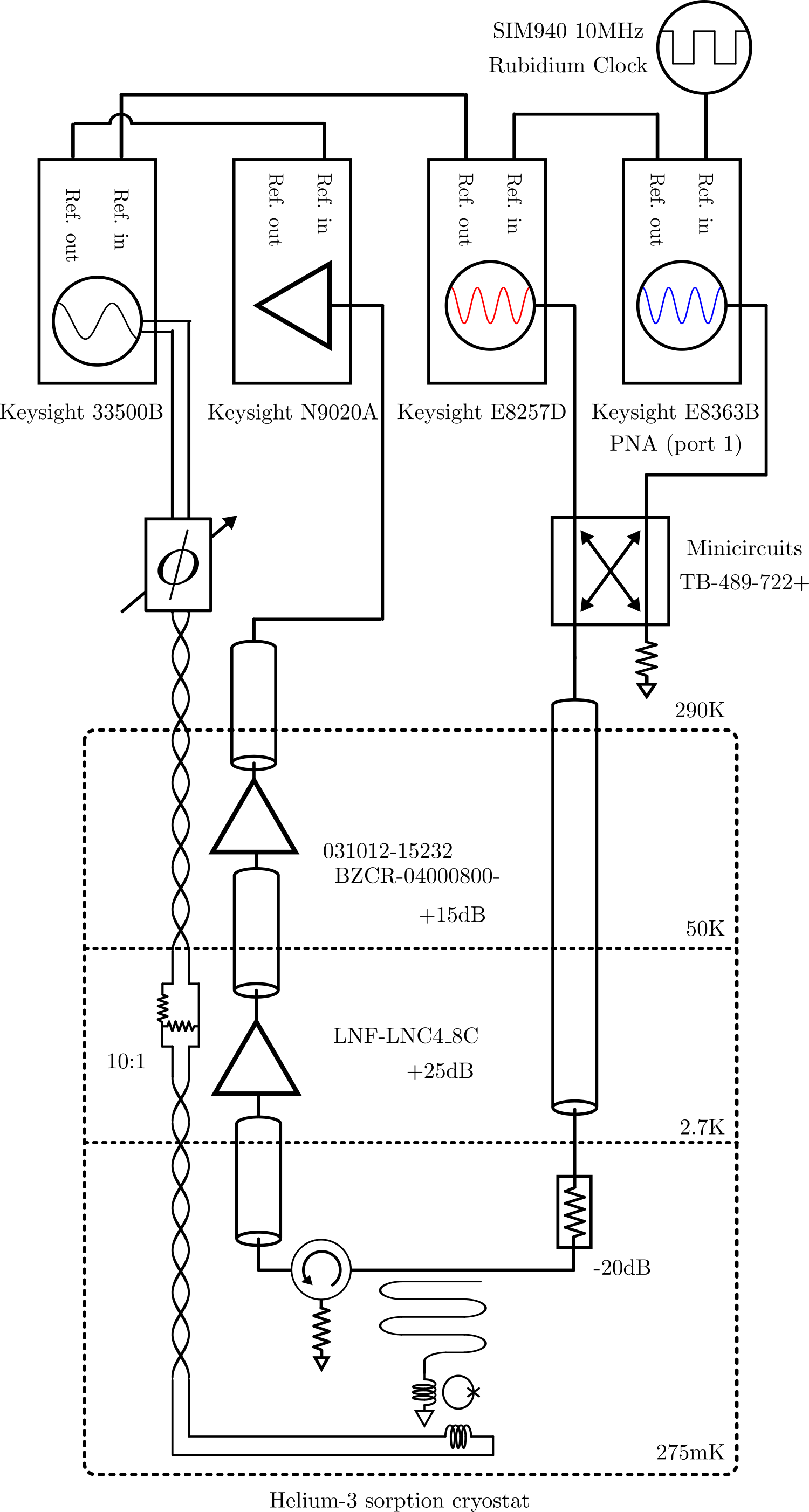
In order to demonstrate phase-sensitive readout, two tones are synthesized in separate microwave generators and combined in a power splitter. A shared 10MHz clock source allowed the microwave synthesizers, a low-frequency function generator, and a microwave spectrum analyser to generate and detect phase-coherent tones, which drive the upconverter.
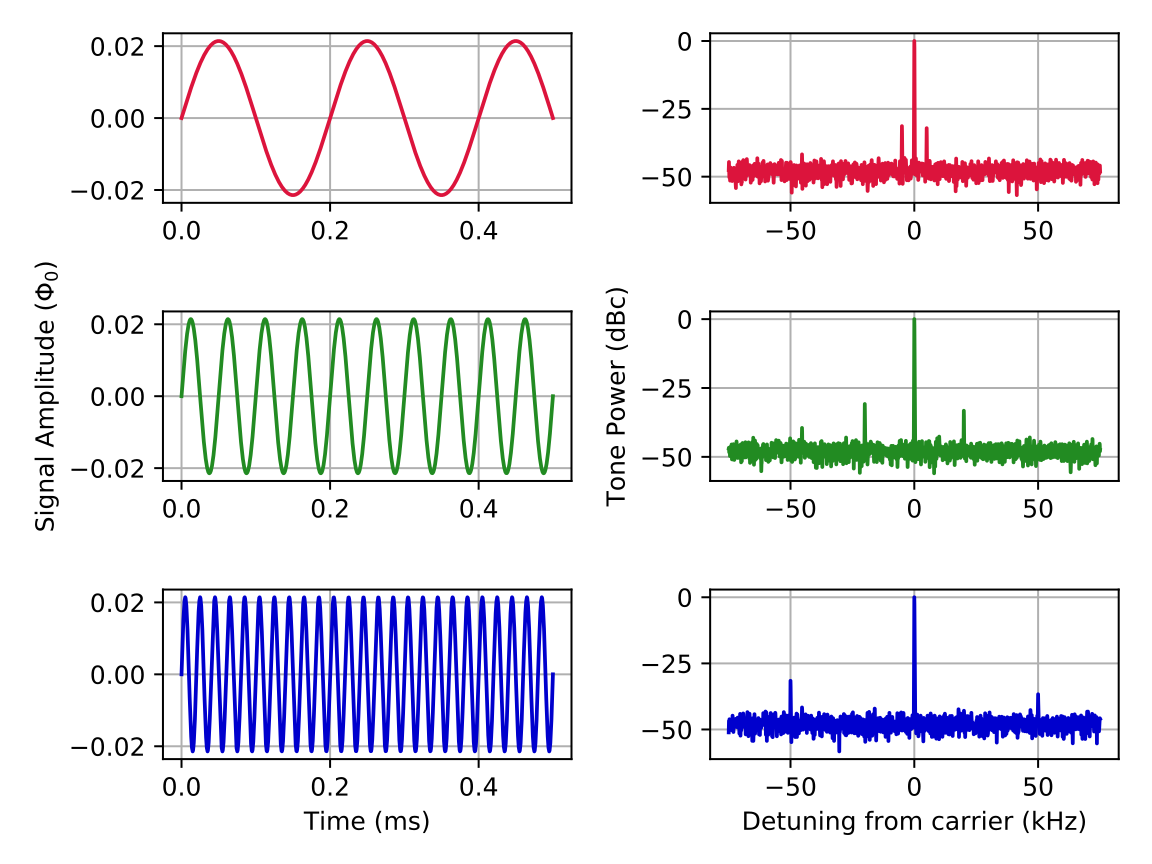
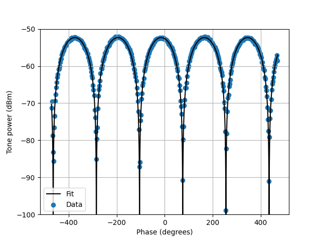
Figure 4, shows a schematic of the setup, in which an RQU is operated at T300mK at the base stage of a 3He sorption cryostat. Filtered and attenuated microwave lines allow for low-noise microwave probe tones to interrogate the RQU, and a High Electron Mobility Transitor (HEMT) amplifier provides low-noise amplification of the tones that transmit past the RQU. A filtered and attenuated twisted-pair line provides flux bias to the SQUID loop of the RQU, allowing for signals up to a few hundred kHz.
We generate tones symmetrically detuned by 2.9MHz from the 4.89 GHz resonance frequency of the upconverter. We also use the flux bias to modulate the SQUID at 2.9 MHz, and sweep the phase of the SQUID modulation tone over approximately 1080 degrees. The spectrum of the transmitted microwave tones is recorded at a spectrum analyzer. As the phase of the flux modulation changes with respect to the envelope defined by the beating of the microwave tones changes, the total power upconverted modulates, showing a phase-sensitive extinction ratio of 46.9 dB.
The high extinction ratio proves the viability of phase-sensitive upconversion, although it does not constitute a true backaction-evading measurement, which will require a high-Q resonant circuit on the input of the upconverter. For this signal frequency and this upconverter, the spurious backaction terms would have limited the degree of backaction evasion to less than 10dB, in any case. However, reducing the microwave loss rate by increasing the microwave quality factor can reduce the spurious backaction, in principle arbitrarily.
VI Conclusions
The RQU a flexible and powerful tool for quantum metrology of low-frequency electromagnetic modes. Using the RQU as a replacement for dc SQUIDs enables amplification at the SQL and in situ tunable noise impedance. These functions are useful in a variety of important magnetometry applications. Moreover, the RQU can be operated as a phase-sensitive amplifier, enabling performance beyond the SQL via backaction evading measurements, which has the potential to dramatically enhance the performance of an important class of fundamental physics experiments. We have demonstrated the basic functionality of upconversion in both phase-insensitive and phase-sensitive modes, converting signals from 5kHz to 3MHz into the microwave C band. The phase-sensitive data has an extinction ratio of 46.9dB, which is a necessary step towards achieving a high degree of backaction evasion in future experiments. This will enable beyond-SQL metrology in a variety of precision experiments, including searches for sbu-eV axion dark matter.
VII Acknowledgments
This work was supported by the US Department of Energy, Office of High Energy Physics program under the QuantISED program, FWP 100667. S. Chaudhuri acknowledges the support of the R.H. Dicke Postdoctoral Fellowship and the David Wilkinson Fund. CY was supported in part by the National Science Foundation Graduate Research Fellowship Program under Grant No. 1656518. Part of this work was performed at the Stanford Nano Shared Facilities (SNSF)/Stanford Nanofabrication Facility (SNF), supported by the National Science Foundation under award ECCS-2026822. Additional microfabrication support was provided by K. Multani, A.Y. Cleland and the Safavi-Naeini group.
References
- (1) A. Blais, J. Gambetta, A. Wallraff, D. I. Schuster, S. M. Girvin, M. H. Devoret, and R. J. Schoelkopf, “Quantum-information processing with circuit quantum electrodynamics,” Physical Review A - Atomic, Molecular, and Optical Physics, vol. 75, p. 032329, 3 2007. [Online]. Available: https://journals.aps.org/pra/abstract/10.1103/PhysRevA.75.032329
- (2) B. R. Johnson, M. D. Reed, A. A. Houck, D. I. Schuster, L. S. Bishop, E. Ginossar, J. M. Gambetta, L. Dicarlo, L. Frunzio, S. M. Girvin, and R. J. Schoelkopf, “Quantum non-demolition detection of single microwave photons in a circuit,” Nature Physics, vol. 6, pp. 663–667, 6 2010. [Online]. Available: www.nature.com/naturephysics
- (3) Y. F. Chen, D. Hover, S. Sendelbach, L. Maurer, S. T. Merkel, E. J. Pritchett, F. K. Wilhelm, and R. McDermott, “Microwave photon counter based on josephson junctions,” Physical Review Letters, vol. 107, p. 217401, 11 2011. [Online]. Available: https://journals.aps.org/prl/abstract/10.1103/PhysRevLett.107.217401
- (4) Y. Nakamura, Y. A. Pashkin, and J. S. Tsai, “Coherent control of macroscopic quantum states in a single-cooper-pair box,” Nature, vol. 398, pp. 786–788, 4 1999. [Online]. Available: www.nature.com
- (5) F. Arute, K. Arya, R. Babbush, D. Bacon, J. C. Bardin, R. Barends, R. Biswas, S. Boixo, F. G. Brandao, D. A. Buell, B. Burkett, Y. Chen, Z. Chen, B. Chiaro, R. Collins, W. Courtney, A. Dunsworth, E. Farhi, B. Foxen, A. Fowler, C. Gidney, M. Giustina, R. Graff, K. Guerin, S. Habegger, M. P. Harrigan, M. J. Hartmann, A. Ho, M. Hoffmann, T. Huang, T. S. Humble, S. V. Isakov, E. Jeffrey, Z. Jiang, D. Kafri, K. Kechedzhi, J. Kelly, P. V. Klimov, S. Knysh, A. Korotkov, F. Kostritsa, D. Landhuis, M. Lindmark, E. Lucero, D. Lyakh, S. Mandrà, J. R. McClean, M. McEwen, A. Megrant, X. Mi, K. Michielsen, M. Mohseni, J. Mutus, O. Naaman, M. Neeley, C. Neill, M. Y. Niu, E. Ostby, A. Petukhov, J. C. Platt, C. Quintana, E. G. Rieffel, P. Roushan, N. C. Rubin, D. Sank, K. J. Satzinger, V. Smelyanskiy, K. J. Sung, M. D. Trevithick, A. Vainsencher, B. Villalonga, T. White, Z. J. Yao, P. Yeh, A. Zalcman, H. Neven, and J. M. Martinis, “Quantum supremacy using a programmable superconducting processor,” Nature, vol. 574, pp. 505–510, 10 2019. [Online]. Available: https://doi.org/10.1038/s41586-019-1666-5
- (6) S. Chaudhuri, P. W. Graham, K. Irwin, J. Mardon, S. Rajendran, and Y. Zhao, “Radio for hidden-photon dark matter detection,” Physical Review D - Particles, Fields, Gravitation and Cosmology, vol. 92, p. 075012, 10 2015. [Online]. Available: https://journals.aps.org/prd/abstract/10.1103/PhysRevD.92.075012
- (7) A. Phipps, S. E. Kuenstner, S. Chaudhuri, C. S. Dawson, B. A. Young, C. T. FitzGerald, H. Froland, K. Wells, D. Li, H. M. Cho, S. Rajendran, P. W. Graham, and K. D. Irwin, “Exclusion limits on hidden-photon dark matter near 2 nev from a fixed-frequency superconducting lumped-element resonator,” in Microwave Cavities and Detectors for Axion Research Proceedings of the 3rd International Workshop, vol. 245. Springer Science and Business Media Deutschland GmbH, 2020, pp. 139–145. [Online]. Available: https://doi.org/10.1007/978-3-030-43761-9_16
- (8) J. L. Ouellet, C. P. Salemi, J. W. Foster, R. Henning, Z. Bogorad, J. M. Conrad, J. A. Formaggio, Y. Kahn, J. Minervini, A. Radovinsky, N. L. Rodd, B. R. Safdi, J. Thaler, D. Winklehner, and L. Winslow, “First results from abracadabra-10 cm: A search for sub- ev axion dark matter,” Physical Review Letters, vol. 122, p. 121802, 3 2019. [Online]. Available: https://journals.aps.org/prl/abstract/10.1103/PhysRevLett.122.121802
- (9) N. Crisosto, P. Sikivie, N. S. Sullivan, D. B. Tanner, J. Yang, and G. Rybka, “Admx slic: Results from a superconducting lc circuit investigating cold axions,” Physical Review Letters, vol. 124, p. 241101, 6 2020. [Online]. Available: https://journals.aps.org/prl/abstract/10.1103/PhysRevLett.124.241101
- (10) A. Garcon, D. Aybas, J. W. Blanchard, G. Centers, N. L. Figueroa, P. W. Graham, D. F. Kimball, S. Rajendran, M. G. Sendra, A. O. Sushkov, L. Trahms, T. Wang, A. Wickenbrock, T. Wu, and D. Budker, “The cosmic axion spin precession experiment (casper): A dark-matter search with nuclear magnetic resonance,” Quantum Science and Technology, vol. 3, p. 014008, 1 2018. [Online]. Available: https://doi.org/10.1088/2058-9565/aa9861
- (11) L. H. Nguyen, A. Lobanov, and D. Horns, “First results from the wispdmx radio frequency cavity searches for hidden photon dark matter,” Journal of Cosmology and Astroparticle Physics, vol. 2019, p. 014, 10 2019. [Online]. Available: https://doi.org/10.1088/1475-7516/2019/10/014
- (12) S. Chaudhuri, K. Irwin, P. W. Graham, and J. Mardon, “Optimal impedance matching and quantum limits of electromagnetic axion and hidden-photon dark matter searches,” arXiv, 3 2018. [Online]. Available: http://arxiv.org/abs/1803.01627
- (13) S. Chaudhuri, K. D. Irwin, P. W. Graham, and J. Mardon, “Optimal electromagnetic searches for axion and hidden-photon dark matter,” arXiv, 4 2019. [Online]. Available: http://arxiv.org/abs/1904.05806
- (14) M. Reagor, W. Pfaff, C. Axline, R. W. Heeres, N. Ofek, K. Sliwa, E. Holland, C. Wang, J. Blumoff, K. Chou, M. J. Hatridge, L. Frunzio, M. H. Devoret, L. Jiang, and R. J. Schoelkopf, “Quantum memory with millisecond coherence in circuit qed,” Physical Review B, vol. 94, p. 014506, 7 2016. [Online]. Available: https://journals.aps.org/prb/abstract/10.1103/PhysRevB.94.014506
- (15) A. Roy and M. Devoret, “Introduction to parametric amplification of quantum signals with josephson circuits,” Comptes Rendus Physique, vol. 17, pp. 740–755, 8 2016.
- (16) M. A. Castellanos-Beltran, K. D. Irwin, G. C. Hilton, L. R. Vale, and K. W. Lehnert, “Amplification and squeezing of quantum noise with a tunable josephson metamaterial,” Nature Physics, vol. 4, pp. 928–931, 10 2008. [Online]. Available: www.nature.com/naturephysics
- (17) R. F. Voss, “Uncertainty principle limit to the energy sensitivity of SQUID’s and other linear amplifiers,” Applied Physics Letters, vol. 38, pp. 182–184, 2 1981. [Online]. Available: http://aip.scitation.org/doi/10.1063/1.92271
- (18) A. A. Clerk, F. Marquardt, and K. Jacobs, “Back-action evasion and squeezing of a mechanical resonator using a cavity detector,” New Journal of Physics, vol. 10, p. 95010, 9 2008. [Online]. Available: http://www.njp.org/
- (19) M. Aspelmeyer, T. J. Kippenberg, and F. Marquardt, “Cavity optomechanics,” Reviews of Modern Physics, vol. 86, pp. 1391–1452, 12 2014. [Online]. Available: https://journals.aps.org/rmp/abstract/10.1103/RevModPhys.86.1391
- (20) D. F. Walls and G. J. Milburn, Quantum optics. Springer Berlin Heidelberg, 2008.
- (21) A. A. Clerk, M. H. Devoret, S. M. Girvin, F. Marquardt, and R. J. Schoelkopf, “Introduction to quantum noise, measurement, and amplification,” Reviews of Modern Physics, vol. 82, pp. 1155–1208, 4 2010. [Online]. Available: https://journals.aps.org/rmp/abstract/10.1103/RevModPhys.82.1155
- (22) R. H. Koch, D. J. V. Harlingen, and J. Clarke, “Quantum noise theory for the dc squid,” Applied Physics Letters, vol. 38, pp. 380–382, 3 1981. [Online]. Available: http://aip.scitation.org/doi/10.1063/1.92345
- (23) V. E. Manucharyan, E. Boaknin, M. Metcalfe, R. Vijay, I. Siddiqi, and M. Devoret, “Microwave bifurcation of a josephson junction: Embedding-circuit requirements,” Physical Review B - Condensed Matter and Materials Physics, vol. 76, p. 014524, 7 2007. [Online]. Available: https://journals.aps.org/prb/abstract/10.1103/PhysRevB.76.014524