The Development of a Multi-Physics Approach for Modelling the Response of Aerospace Fastener Assemblies to Lightning Attachment
Abstract
This work is concerned with the development of a numerical modelling approach for studying the time-accurate response of aerospace fasteners subjected to high electrical current loading from a simulated lightning strike. The electromagnetic, thermal and elastoplastic response of individual fastener components is captured by this method allowing a critical analysis of fastener design and material layering. Under high electrical current loading, ionisation of gas filled cavities in the fastener assembly can lead to viable current paths across internal voids. This ionisation can lead to localised pockets of high pressure plasma through the Joule heating effect. The multi-physics approach developed in this paper extends an existing methodology that allows a two-way dynamic non-linear coupling of the plasma arc, the titanium aerospace fastener components, the surrounding aircraft panels, the internal supporting structure and internal plasma-filled cavities. Results from this model are compared with experimental measurements of a titanium fastener holding together carbon composite panels separated by thin dielectric layers. The current distribution measurements are shown to be accurately reproduced. A parameter study is used to assess the internal cavity modelling strategy and to quantify the relation between the internal cavity plasma pressure, the electrical current distribution and changes in the internal cavity geometry.
Keywords: lightning strike; multi-physics; aerospace fastener; multi-material; ghost-fluid method; Joule heating; structural response
I Introduction
Composite materials now make up more than 50% of a modern aircraft design by weight krauklis2020composite . This is due to higher specific strength and better fatigue properties for high tension components than conventional aluminium alternatives. Composite materials also have lower electrical and thermal conductivity than the supplanted aluminium, which can adversely affect the response of aircraft components to lightning strikes. The initial stages of a lightning strike results in a large current flow through the aircraft skin, which, for materials with low electrical conductivity can result in large energy input through Joule heating. In Carbon Fibre Reinforced Polymer (CFRP), for example, the high energy input can result in fibre fracture, resin decomposition, delamination and thermal ablation.
The interaction of lightning with aircraft exterior surfaces can be further complicated by the integration of conductive components, such as metallic fasteners, with higher conductivity than the surrounding composite substrates. Aerospace fasteners, used to join skin panels, are commonly manufactured from titanium alloys that are lightweight, strong and corrosion resistant. These can, however, act as a preferred pathway for the current to access the internal airframe and embedded carbon composite panels. High current flow through a fastener can arise either from a direct attachment of a lightning arc to the fastener head or indirectly as current conducted from a remote attachment site. In addition to paint, panel and sealant damage, the high current flow in the metallic fastener can cause a thermal ejection of hot particles (energetic discharge) from the interfaces between fastener components. Energetic discharge from fastener assemblies can represent a potential threat in safety critical regions of an aircraft, such as in integrated fuel tanks where significant fuel vapour is present.
Chemartin et al. chemartin2012direct outline three important mechanisms through which a fastener can undergo energetic discharge. The first, termed ‘outgassing’, results from the current passage across small resistive gaps between the fastener and skin. The formation of a plasma in the gap, and subsequent Joule heating, increases the internal plasma pressure until a blow out of sparks and hot gas occurs at the component interface. Further information regarding the characteristics and causes of outgassing (also known as pressure sparking) is provided in the comprehensive review of Evans evans2018thesisCharacterisation . The second energetic discharge mechanism outlined in Chemartin et al. chemartin2012direct is thermal sparking between contacting components, i.e., the fastener nut and rib. Odam et al. odam1991lightning ; odam2001factors suggests that thermal sparking occur when a very high current is forced to cross a joint between two conducting materials, which have imperfect mating between their surfaces. This process is noted to be distinct from voltage sparking, which occurs when the voltage difference between two conducting materials is sufficient to break down the intervening medium, whether this is air or another dielectric medium. The final energetic discharge mechanism outlined in Chemartin et al. chemartin2012direct is edge glow. This is defined by Revel et al. revel2016edge as consisting of a bright glow combined with strong material ejections, and occurs on the edges of composite materials. Two mechanisms responsible for the presence of edge glow are proposed in the available literature. The first of these occurs when the potential difference between adjacent composite plies exceeds a threshold value, irrespective of whether a pre-existing contact between the plies is present. The second mechanism occurs when the power deposition into the substructure is above a threshold power value that produces a glow due to heating of sealant.
These energetic discharge mechanisms can been distinguished using an appropriate experimental approach. Day and Kwon kwon2009optical describe a method which analyses light over a narrow spectral range using a spectrometer and can identify hot particle ejection, arcing and edge glow. Work by Haigh et al. haigh1991measurements , in contrast, applies two-colour spectroscopy to estimate the temperature of sparks emitted using red/blue ratios, comparing with baseline nickel and tungsten sparks. Later work by Haigh et al. haighCrookTerzino2013 uses photography to detect light sources that are potential ignition hazards on a T-joint section with multiple fasteners. Focusing specifically on outgassing events, Mulazimoglu and Haylock mulazimoglu2011recent relate sparking intensity to the fastener material and geometry choice using energy dispersion spectrometer chemical analysis, and determine that the principle constituent of the ejected particle debris in question is polysulphide sealant, with small quantities of metallic droplets and carbon fibre particles. They surmise that the chemical composition of the debris mean that electrical arcing occurs between the bolt and the CFRP hole surface. The ablated material is then carried by hot gases during the outgassing ejection event due to the arcing pressure. The microstructure of the resulting damage is analysed using scanning electron microscopy and the outgassing characteristics that result from deliberate design additions are analysed. These additions include the introduction of metallic sleeve components, dielectric bolt head coverings and bolt-line metallic meshes.
The wide range of potential fastener configurations, along with the various mechanisms through which sparking can occur, mean that computational simulation can provide an efficient and cost effective technique for rapidly exploring the available parameter space. Computational techniques can also provide a useful tool in the design of experimental testing for proposed fastener configurations. Finite element methods, for example, are a common, single-material approach to model the effects of high current flow through carbon composite substrates. This is achieved through prescribing a current waveform along the upper surface, see, for example Ogasawara et al. ogasawara2010coupled , Abdelal and Murphy abdelal2014nonlinear , Guo et al. guo2017comparison , Dong et al. dong2015coupled , Wang et al. wang2014ablation and Liu et al. liu2015combining and for commercial software by Wang and Pasiliao wang2018modeling , Kamiyama et al. kamiyama2018delamination ; kamiyama2019damage , Fu and Ye fu2019modelling and Evans et al. evans2014comsolansys . The prescription of a current waveform along the upper surface of a composite material is perhaps most suited to cases in which the damage to individual ply and resin layers is of direct interest, since inter-ply loading and damage characteristics can be efficiently modelled using modest computational resources for comparison with experimental results. Modelling a lightning strike using this approach in isolation can, however, neglect the dynamic change in current and pressure loading on the upper surface of the substrate by an evolving plasma arc, and the non-linear feedback from these changes, which in turn affect the arc behaviour.
To allow the evolution of the plasma arc to effect the time-dependent substrate current and pressure loading, the ‘co-simulation’ approach couples two software packages or approaches. Using this technique a magnetohydrodynamic (MHD) code can be used to describe the evolution of temperature, pressure and current density within the arc. The results of running the MHD code are then fed as initial and boundary conditions to a second simulation that models the mechanical, thermal and electrodynamic evolution of the substrate. Examples of this approach include Tholin et al. tholin2015numerical , who couple two distinct software packages (Cèdre and Code–Saturn) to model the plasma arc attachment to single material substrates, and Millen et al. millen2019sequential who couple two commercial software packages (COMSOL Multiphysics and Abaqus FEA) to model the mechanical loading and electromagnetic effects on a carbon composite substrate. Kirchdoerfer et al. kirchdoerfer2017 ; kirchdoerfer2018cth apply the co-simulation approach to aerospace fasteners, coupling the results from COMSOL Multiphysics with a research shock-physics code developed at Sandia National Laboratories (CTH). The electric and magnetic fields, and current density, are solved in COMSOL and used to determine Joule heating effects. One-way coupling is then applied with the CTH solver using an effective heating power, computed from the modelled Joule heating, allowing the simulation of the fluid-structure interaction. This one-way coupled solution is used to determine the temperature and pressure rise in an internal cavity between a bolt, nut, and surrounding CFRP panels, with the final pressure rise being compared to experimental results.
The co-simulation approach results in a one-directional coupling between materials where the substrate behaviour does not influence the evolution of the arc. However, experimental results, such as the optical measurements of Martins martins2016etude , indicate that changes in the electrical conductivity and substrate shape can alter the arc attachment characteristics. This work uses a multi-physics methodology introduced in Millmore and Nikiforakis millmore2019multi , to simulate a dynamic non-linearly coupled system comprising the plasma arc, titanium aerospace fastener components, surrounding aircraft panels and the internal supporting structure. The electromagnetic, thermal and elastoplastic response of individual fastener components is captured by this method, allowing a critical analysis of fastener design and material layering. Dynamic feedback between the components is achieved in this multi-physics approach by simultaneously solving the governing hyperbolic partial differential equations for each material in a single system. The non-linear dynamic feedback between adjacent materials achieved by this approach provides a distinct improvement over existing numerical methods for modelling lightning strike attachment. The underlying numerical methods and implementation used in this paper are outlined in Millmore & Nikiforakis millmore2019multi , and extended in Michael et al. michael2019multi and Träuble et al. trauble2021improved . Millmore and Nikiforakis compare numerical results from the non-linear multi-physics approach used in this paper with the optical measurements of Martins martins2016etude , for a plasma arc attachment to a single material substrate, and demonstrate that the two-way interaction between the substrate and plasma is accurately captured by this method.
The key aim of this work is to use this approach to model the rise in pressure within an internal cavity between a titanium fastener and a CFRP panel. The breakdown of air in this cavity requires a strategy for defining an internal plasma region, and the influence of parametric changes in the cavity geometry on the pressure rise through Joule heating can be studied. This mechanism is acknowledged by Chemartin et al. chemartin2012direct and Evans evans2018thesisCharacterisation as a major contributing factor in outgassing, hence this paper focuses on this mechanism over thermal sparking and edge glow. An overview of the multi-physics methodology is given in section II and an assessment of the methodology for modelling lightning strikes on aerospace fasteners is made in section III. The model is validated by comparing to experimental measurements of a fastener holding together carbon composite and aluminium panels, electrically isolated from each other by a dielectric layer. The multi-physics methodology is then exercised in section IV to investigate how parametric changes in the design of an idealised fastener influence the pressure loading, component temperature rise and electrical current path characteristics. This study considers a variety of fastener design and material layering choices, and permits the pressure rise in confined internal plasma regions to be numerically quantified. Section V provides a summary and an outlook to future work.
II Mathematical Model Description
This section gives an overview of the mathematical model used to simulate the response of aerospace fastener assemblies to lightning attachment.
II.1 Plasma model
The plasma arc is described through a system of equations suitable for simulating the evolution and ionisation of air caused by an electric discharge. This model must describe the change in the chemical composition of the plasma under the high temperatures of the arc. Additionally electromagnetic effects can have a strong influence on the arc evolution. This requires an MHD formulation which includes the effects of current flow in the arc through the Lorentz and Joule effects. For lightning plasma, this system can be assumed to be under local thermodynamic equilibrium tholin2015numerical ; martins2016etude . The governing system of equations is therefore given by
| (1) |
| (2) |
| (3) |
| (4) |
where is density, is velocity, is the pressure, is the total energy, is the current density, is the magnetic field, is the resistivity of the plasma, is a term for the radiative losses from a heated material, and is the magnetic vector potential, related to the magnetic field through . The current density is governed by the continuity equation.
| (5) |
where is the electric potential and is the electrical conductivity of the plasma arc.
II.1.1 Equation of state
The system of equations (1)–(4) comprises 8 equations for 10 unknown variables, , , and the vectors , and . These are closed using equation (5) and an equation of state which describes the thermodynamic properties of the system. The equation of state is typically written in the form , where is the specific internal energy, and is related to the total energy through . The equation of state of a plasma is complex, since its thermodynamic properties depend strongly on the degree of ionisation.
To capture this behaviour, a tabulated equation of state for air plasma is used in this paper. This was developed by Träuble et al. trauble2021improved , based on the theoretical model of d’Angola et al. d2008thermodynamic . This considers the 19 most important species present in an air plasma at temperatures up to K over a pressure range of atm.
II.2 Elastoplastic model
In this work, the material substrate uses an elastoplastic solid model described by Barton et al. Barton20097046 and Schoch et al. schoch2013eulerian ; schoch2013propagation , based on the formulation by Godunov and Romenskii godunov1972nonstationary . The plasticity model follows the work of Miller and Colella miller2001high . The elastoplastic implementation used in the present work is described in Michael et al. michael2019multi , therefore only a brief overview is provided here for completeness.
To account for the material deformation, the elastic deformation gradient is defined as
| (6) |
which maps a coordinate in the original configuration, , to its evolved coordinate in the deformed configuration, . The deformation gradient, along with the momentum, energy and a scalar material history parameter, , give a hyperbolic system of conservation laws
| (7) |
| (8) |
| (9) |
| (10) |
| (11) |
where is the stress tensor, given by
| (12) |
and is the specific internal energy. The scalar material history, , tracks work hardening of the material through plastic deformation. Source terms associated with the plastic update are denoted . The density is given by
| (13) |
where is the density of the initial, unstressed material and the system is coupled with compatibility constraints on the deformation gradient
| (14) |
which ensure deformations of the solid remain physical.
II.2.1 Equations of state for elastoplastic materials
As with the plasma model, in order to describe the thermodynamic properties of the model, and to close the system of equations (7)–(11), an equation of state is required. A variety of solid materials are used in aerospace fasteners, in particular, aluminium, composite materials, titanium, dielectric coatings and sealants. Additionally, experimental studies include an electrode, which is typically tungsten or steel. This is used to generate a plasma arc and evolution within this electrode does not affect the simulation dynamics (and damage issues are not an issue for simulation purposes). Therefore any conductive metal is typically used as a substitute.
Aluminium is typically described through a Romenskii equation of state Barton20105518 , for which the specific internal energy of the metal is given by
| (15) |
where
| (16) |
and these are the bulk speed of sound and the shear wave speed respectively, with being the sound speed, is the entropy, is the heat capacity at constant volume and a reference temperature. The constants , and are related to the non-linear dependence of sound speeds on temperature and density, and must be determined experimentally for each material. The quantities are invariants of the Finger strain tensor , and are given by
| (17) |
The entropy is computed from the primitive variables and a reference density ,
| (18) |
The parameters for aluminium, as used in Barton et al. barton2010eulerian , are given by
| (19) |
Carbon composites are anisotropic materials, and thus have a more complex equation of state. These are described in the work of Lukyanov lukyanov2010equation , though their implementation in this model is, at present, beyond the scope of this work. Additional work is required within the elastoplastic model described above to deal with material anisotropy. Following Millmore and Nikiforakis millmore2019multi , an isotropic approximation to CFRP can be made, which is suitable for modelling ‘with weave’ and ‘against weave’ configurations due to the symmetries of the problem. This isotropic approximation uses the equation of state as for aluminium, but with electrical conductivity values that approximate CFRP.
A Romenskii equation of state is used for modelling titanium components due to the lack of readily available equations of state for this material. In the configurations considered in this work, electromagnetic effects dominate, and thus this approximation does not have a significant effect on the evolution. The parameters for this equation of state are
| (20) |
The dielectric coatings on aircraft skins are similarly complex, often comprising several layers of material and equations of state for these materials are not openly available. For such coatings used in this work, the plastic polymethyl methylacetate (PMMA) is used, which has been widely studied due to its use in improvised explosives Christou201248 ; hamada2004performance . For PMMA, a Mie-Grüneisen equation of state is employed which directly relates pressure and density through
| (21) |
where and again refer to the speed of sound in the material and the reference density, whilst is a single experimentally determined coefficient. These quantities are given by
| (22) |
For all materials, an electrical conductivity is also required for use in equation (8). Over the temperature ranges observed within the substrate, this can be considered constant for all three materials used in this work. The electrical conductivity employed for aluminium is Sm-1 (e.g., Tholin et al. tholin2015numerical ), for titanium: Sm-1 and for PMMA: Sm-1. The electrical conductivity for PMMA is several orders of magnitude lower than all other materials used and approximates a dielectric layer. The carbon composite is modelled using the isotropic approximation of Millmore and Nikiforakis millmore2019multi where, unless otherwise stated, a bulk electrical conductivity of Sm-1 is used.
II.3 Numerical approach
The coupled multi-physics system requires the solution for the plasma, equations (2)-(3), and for the elastoplastic solid components, equations (7)-(10), each of which is a hyperbolic system of partial differential equations. In addition, we require the elliptic magnetic field, equations (4) and (5), which exist for all materials. The hyperbolic equations are solved using a finite volume methodology; in this case, a second order, slope limited centred method is employed for solving the discrete form of the equations and updating each material independently.
Information is passed across material boundaries using a ghost fluid method, with level set methods (one for each material) being used to track the location of the interfaces between each material. Dynamic boundary conditions are applied at the interfaces using the Riemann ghost fluid method of Sambasivan and Udaykumar sambasivan2009ghost1 , which provides these conditions through a mixed-material Riemann solver. The projection method of Lasasso et al. losasso2006multiple is used to correct the level set for non-unique level-set values caused by potential numerical approximation errors. A comprehensive overview of the multi-material approach used in this work is given by Michael et al. michael2019multi .
The elliptic equations are solved by coupling the system to a finite element solver, in this case, the DOLFIN package for the FEniCS framework langtangen2016solving is used.
III Experimental comparison of the numerical model
In this section the multi-physics methodology is applied to an aerospace fastener configuration used in experimental testing by Evans evans2018thesisCharacterisation . This can validate the suitability of the approach outlined in this paper for modelling high current flow through a complex fastener geometry, comprising a number of materials with different electrical and thermal properties in contact. Specifically, a high conductivity titanium fastener surrounded by successive horizontal layers of carbon fibre and dielectric is modelled. The methodology used in this paper has previously been validated against experimental results for lightning strikes on thin aluminium and carbon composite panels by Millmore and Nikiforakis millmore2019multi . The experiment of Evans evans2018thesisCharacterisation , used in this section, investigates the electrical resistance and current distribution in a countersunk fastener assembly under attachment of an arc with a 50kA peak current density, an experimental input which is representative of a lightning strike. The countersunk head fastener design is typically used in practice to maintain the smooth profile of the external aircraft skin. An interference fit of the fastener with the surrounding CFRP and Glass Fibre Reinforced Polymer (GFRP) layers is used in the experiment and is replicated in this simulation. An axisymmetric simulation models the physical experiment in which a cylindrical fastener is surrounded by a square carbon fibre panel. Return fasteners are equally spaced along the outer edge of the panel in the experiment, justifying the axisymmetric approach. A two-dimensional cross-section of the simulation set-up is given in figure 1.
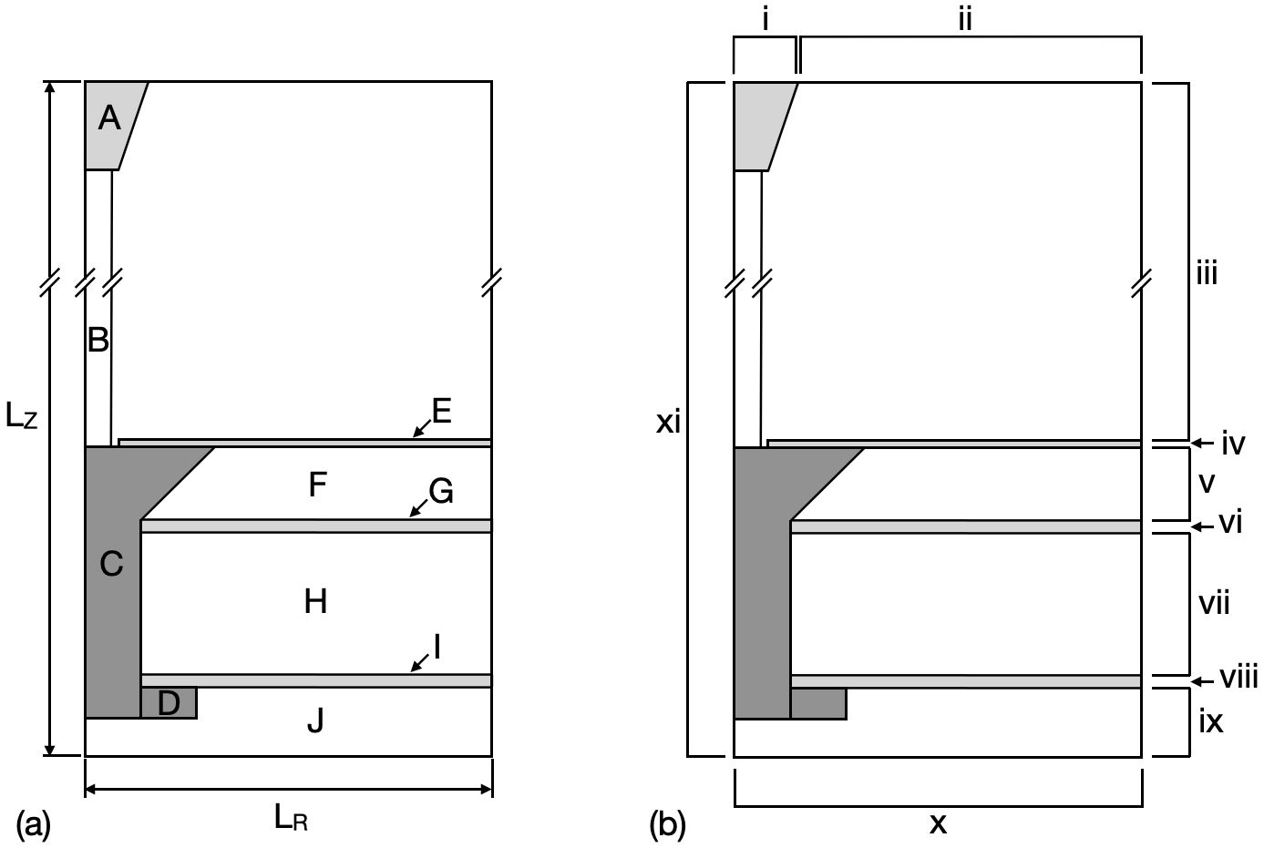
Figure 1 (a) identifies individual fastener material components using the labels C-I. In addition, the electrode and pre-heated arc are identified using labels A and B for reference and the ambient air below the fastener assembly is labelled J. The radial, , and axial, , lengths of the computational domain are also shown, where in this work =50.8 mm and =62 mm. The countersunk titanium fastener, labelled C in figure 1 (a), has a shank diameter of 6.35 mm. The titanium retaining nut, labelled D, has an outer diameter of 12.4 mm. In the experiment of Evans, a high voltage electrode is placed in contact with the fastener head. To replicate this in the present work, in which an electrode is placed 40 mm above the fastener head, a thin dielectric layer (labelled E) is positioned between the arc and the CFRP panel. This dielectric layer, which is 0.6 mm thick, ensures that the radially expanding arc maintains contact only with the fastener head throughout the simulation. The upper panel, labelled F, is 2.032 mm thick and is directly in contact with the fastener head. To electrically isolate the upper panel from the fastener shank and from the lower panel, a further 0.844 mm thick GFRP dielectric layer, labelled G, is placed between the two panels. The lower carbon fibre panel, labelled H in figure 1 (a) is in electrical contact with the fastener shank only and is 6.096 mm thick. To electrically isolate the fastener collar from the lower panel, a further dielectric layer is used, labelled I, and is 0.5 mm thick. Above the fastener head, a 4 mm wide plasma arc is initially defined with a temperature of 8000 K, this is labelled B in figure 1 (a). This pre-heated region is necessary since the breakdown of the air, forming the initial plasma arc, is not modelled in this framework. This region is given a sufficient temperature such that a conductive path is formed between the electrode and the substrate, based on the approach of Chemartin et al. chemartin2011modelling . Larsson et al. larsson2000lightning test a number of initial high temperature (pre-heated) columns up to 20,000K and conclude that the values within the preheated region do not affect the overall evolution of the plasma arc. Due to the lack of available equations of state for GFRP, these layers are approximated in this work using a PMMA equation of state. For simulating the isotropic approximation to CFRP used in this work, an electrical conductivity of Sm-1 is used, as defined by Evans evans2018thesisCharacterisation . At the electrode, a modified ‘Component A’ electrical current waveform, as defined in ARP 5412B ARP5412B , is applied. For this test, the input current waveform has a peak current of 50 kA and is given by,
| (23) |
where, = 51,000 s-1, = 90,000 s-1, = 5,423,540 s-1 and = 243,000 A. Outside of the plasma arc, the unionised gas is initialised using ambient ideal gas conditions.
Figure 1 (b) highlights the boundary conditions applied in the simulation by labelling eleven regions of interest, i-xi. Conditions are required for the conserved variables, , the electrical potential, , as well as the radial and axial components of magnetic field, and , as defined in table 1.
| Boundary | q | |||
|---|---|---|---|---|
| i | Transmissive | |||
| ii | Transmissive | |||
| iii | Transmissive | |||
| iv | Transmissive | |||
| v | Transmissive | |||
| vi | Transmissive | |||
| vii | Transmissive | |||
| viii | Transmissive | |||
| ix | Transmissive | |||
| x | Transmissive | |||
| xi | Symmetry |
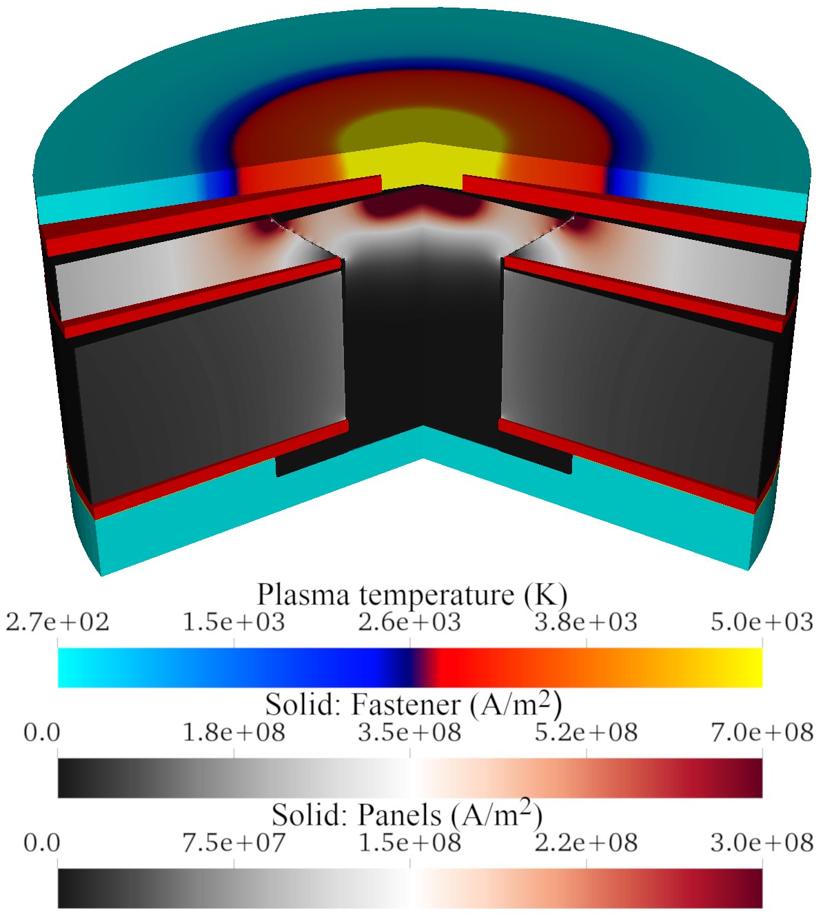
Figure 2 shows a snapshot of this test case at a time of 30 s. This plot shows current density within the composite substrate materials and the temperature within the plasma arc; the dielectric layers are shown in red. The regions of highest current density are highlighted as being at the attachment point at the top of the countersunk fastener bolt head, at the outer radial tip of the countersunk head and along the upper panel. It is clear that the preferred path for current flow is through the upper panel, close to the surface. A localised peak in current density magnitude is visible at the upper radial edge of the countersunk fastener head, at the interface with the upper carbon composite panel. The difference in electrical conductivity between the titanium fastener and the low conductivity panels results in a preference for the current path to remain in the higher conductivity fastener for as long as possible. The shape of the countersunk fastener head outer edge acts to promote a gradient in current density magnitude between the top and bottom of the upper carbon composite panel, at the interface with the fastener. Together with the small axial cross sectional area of the fastener at the tip of the countersunk head, this results in a local peak in current density magnitude, and could cause issues with high localised temperature and pressure through Joule heating. The experimental post-test specimen in Kirchdoerfer et al. kirchdoerfer2017 shows the greatest arc-induced erosion of the CFRP panel at this location in their countersunk fastener case using a 40 kA peak current waveform. At the bottom of the fastener in figure 2, the electrical isolation of the fastener nut by the bottom dielectric layer results in extremely low current density magnitude values in the fastener shank and nut at this location.
In the experiment of Evans evans2018thesisCharacterisation , the current flow through the upper and lower composite panels are measured independently using alternating cut-out sections at the outer edge of each panel so that each return fastener contacts only the upper or lower panel. The relative proportion of total current passing through the upper and lower panels is then measured over time. The electrical current share is computed from the simulation results by integrating current density along a line normal to the current flow direction. This line is taken at a radius of 12 mm; at which point the current density streamlines were effectively purely radial. The measurements of Evans show that for an interference fit fastener, over three quarters of the total current passes through the upper panel, identifying this route as the preferred current path. Figure 3 compares the experimental and simulation results for the relative share of total current passing through the upper and lower composite panels over the first 40 s.
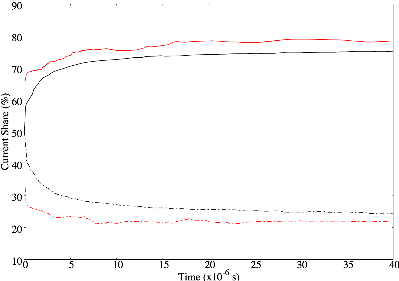
Comparing the simulation and the experiment in figure 3, there is a similar distribution of current between the upper and lower panels in both cases. The significantly higher proportion of current flowing through the upper panel reflects the large area of contact between the upper panel and the fastener head, as well as the preference for current to travel via the least resistive route to ground. The percentage of current passing through the upper panel is slightly greater in the simulation than in the measurements of Evans evans2018thesisCharacterisation . This may in part be due to the difference in current input at the top of the fastener, with the simulation using an attached arc, rather than a point source. The radial expansion of the arc increases the contact area between the simulated arc and fastener head. Once the arc radius has increased past the radius of the fastener shank, a significant proportion of the current density input is close to the outer radius of the fastener head, resulting in a greater current flow across the short distance between the top of the fastener head an the upper panel. However, the close match in behaviour over time does confirm that this computational approach is capable of simulating the transient current flow in a complex fastener geometry comprising a number of distinct layers of materials with differing electrical and thermal properties.
IV Fastener design sensitivity studies
This section considers the influence of fastener design choices in the distribution of current flow and associated pressure and temperature increases in the fastener assembly. In section IV.1 the location of dielectric layers in the fastener assembly is considered. Dielectric layers can be included in fastener assemblies through judicious design to control current flow away from sensitive components, or as a result of component sealant and resin use. The inclusion of a clearance gap between the fastener shank is also considered in this section by comparison with an interference fit type fastener. Section IV.2 develops the clearance fit gap analysis by considering the necessity in the present numerical modelling method for pre-heating of the clearance fit gap to promote an electrically conductive path across the gap. The effect of clearance gap width is then considered in section IV.3, both with and without pre-heating. All simulations in this section use the current described by equation (23) with parameters as defined in ARP 5412B ARP5412B , = 11,354 s-1, = 647,265 s-1, = 5,423,540 s-1 and = 43,762 A.
IV.1 The effect of dielectric layers and fastener clearance fitting
The multi-physics methodology outlined in section II allows not only the mechanical, thermodynamic and electrodynamic evolution of an aerospace fastener subject to lightning attachment to be captured, but also for the sensitivity of these properties to changes in fastener design to be assessed.
Figure 4 shows an example of two different idealised aerospace fastener configurations. Both fasteners comprise a titanium nut and bolt and a single carbon composite panel. An electrode is placed 40 mm above the substrate surface, and a pre-heated region exists between this and the substrate.
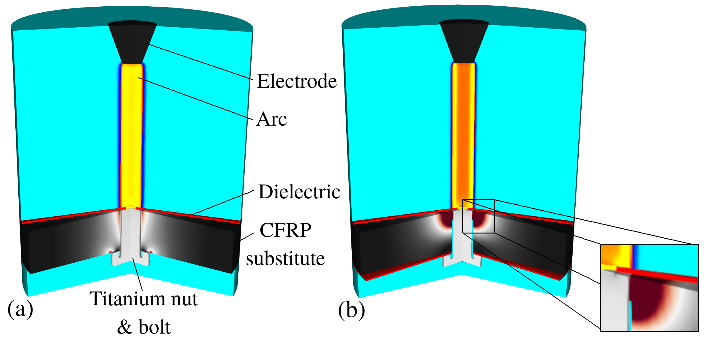
The first fastener design, shown in figure 4 (a), has a dielectric coating layer on the upper face of the carbon composite panel. This layer, which is 0.5 mm thick, represents, for example, a painted surface or other coating. The titanium bolt is 6 mm in diameter and is in direct contact with a composite panel of thickness 12 mm, representing an interference-type fit. A titanium nut, of diameter 12 mm and thickness 2 mm, is in direct contact with the lower face of the carbon composite panel. The second idealised fastener design, figure 4 (b) has dielectric layers at both upper and lower surfaces of the carbon composite panel, each of thickness 0.5 mm. A clearance fit air gap between the titanium bolt and the surrounding carbon composite panel of width 0.3 mm is defined in the second fastener design. This is shown as a enlarged region in figure 4 (b). The only area of direct contact between the fastener bolt and the carbon composite panel is a 2.5 mm length directly below the top dielectric layer.
In both fastener designs, a pin hole punctures the radial centre of the upper dielectric layer. This pin hole is a technique frequently used in lightning experiments, and is used in this case to initialise a conductive path between the plasma arc and the titanium fastener. In practice, this pin hole may crudely represent a small region of dielectric ablation during the initial attachment of the lightning strike. The diameter of the hole at the centre of the upper dielectric layer is reduced from 6 mm to 3 mm in the latter configuration. The final difference between the two configurations is the introduction of a narrow strip of non-ionised air between the fastener shank and the panel. In order to reduce the computational resolution overhead in these idealised fastener designs, the thread between the bolt and nut is neglected.
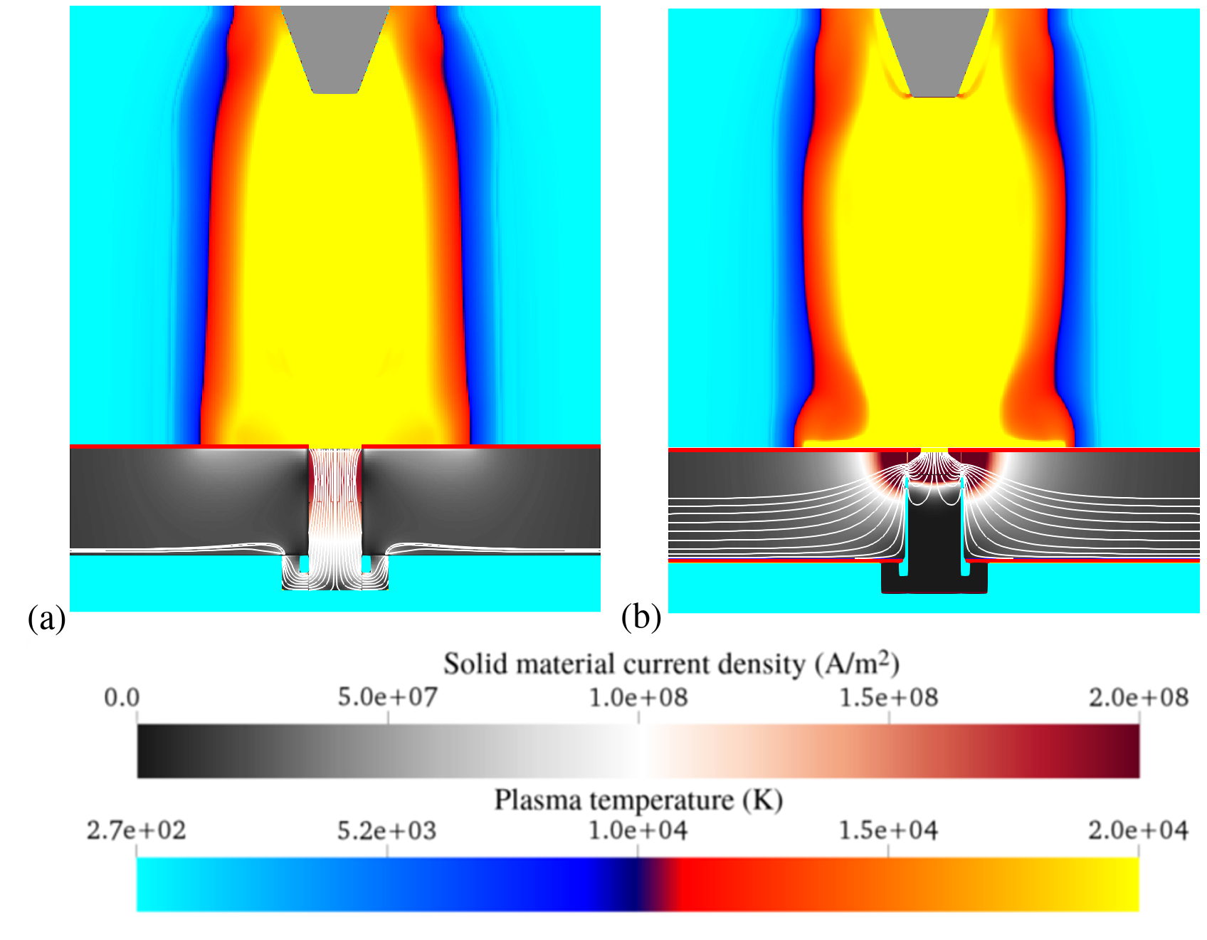
Figure 5 shows the current density profiles in the substrate, and temperature in the plasma arc, for the two fastener configurations shown in figure 4 at a time of 20 s. Current density streamlines are also shown in the substrate materials. As expected, for the first fastener configuration in figure 5 (a), the main electrical current path is along the titanium fastener bolt, through the titanium nut and into the lower face of the carbon composite panel to the ground location at the outer radius of the panel. The second fastener configuration, figure 5 (b), is electrically insulated between the titanium nut and the panel, and due to the clearance fit used in this case, the preferred path for current is through the small region of contact between the fastener and the panel.
This results in high current density close to the top of the fastener, seen in figure 5 (b), and subsequent current flow into the substrate at this point. It is clear from the current density streamlines that the subsequent flow through the panel is then spread over a wider area than in the case where the lower dielectric layer is not used.
The reduction in the hole diameter of the upper dielectric and changes in current density magnitude also influence the shape of the arc above the fastener. A local radial restriction, or ‘pinching’, of the plasma arc is evident in figure 5 (b), immediately above the attachment point; this pinching is not evident to the same extent in figure 5 (a). The ability for the present numerical method to identify the dependence of arc characteristics on the configuration, material choice and layering of the substrate highlights the advantage of a fully coupled system. This coupling was demonstrated and validated against experimental results in Millmore and Nikiforakis millmore2019multi .
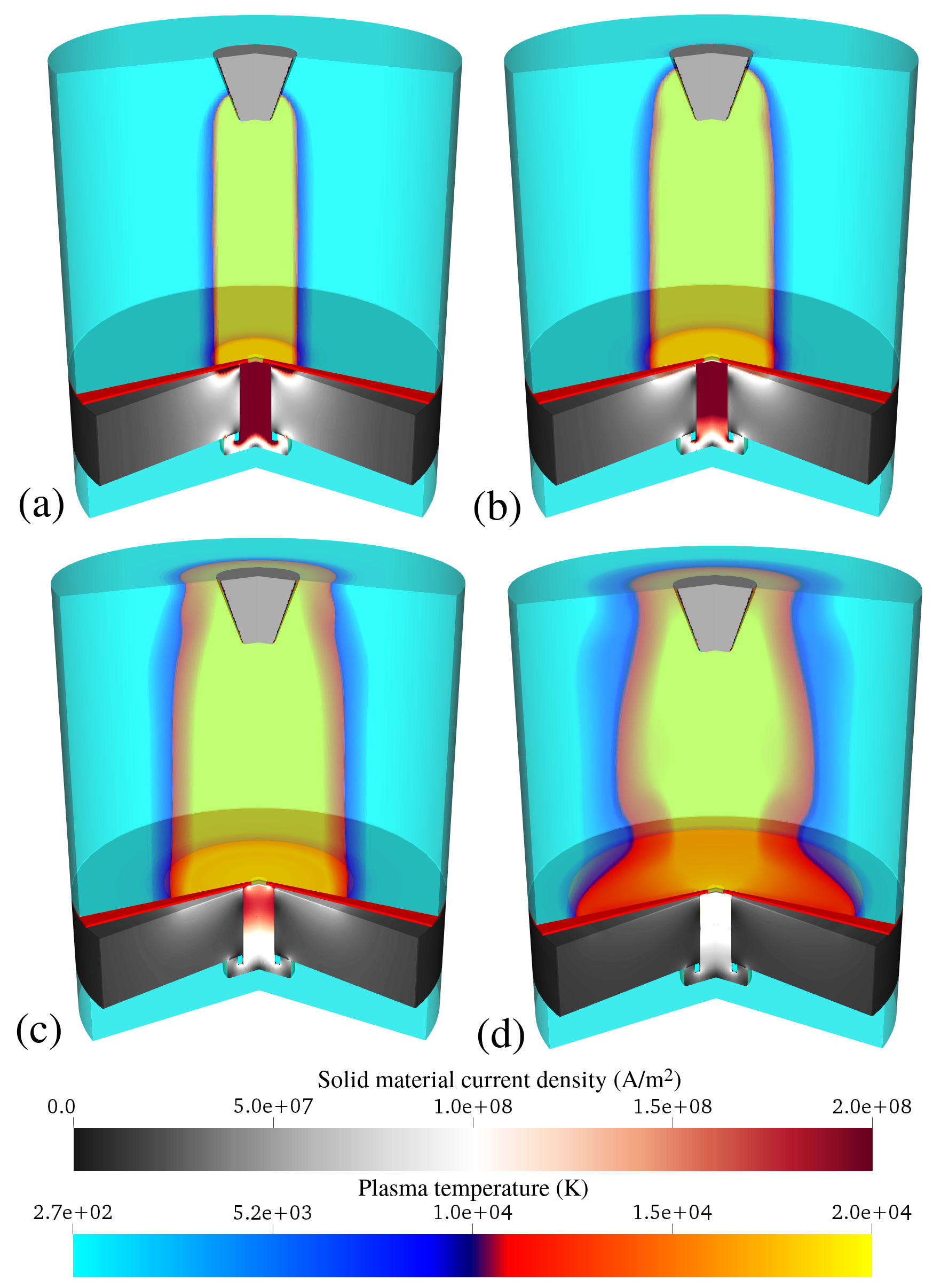
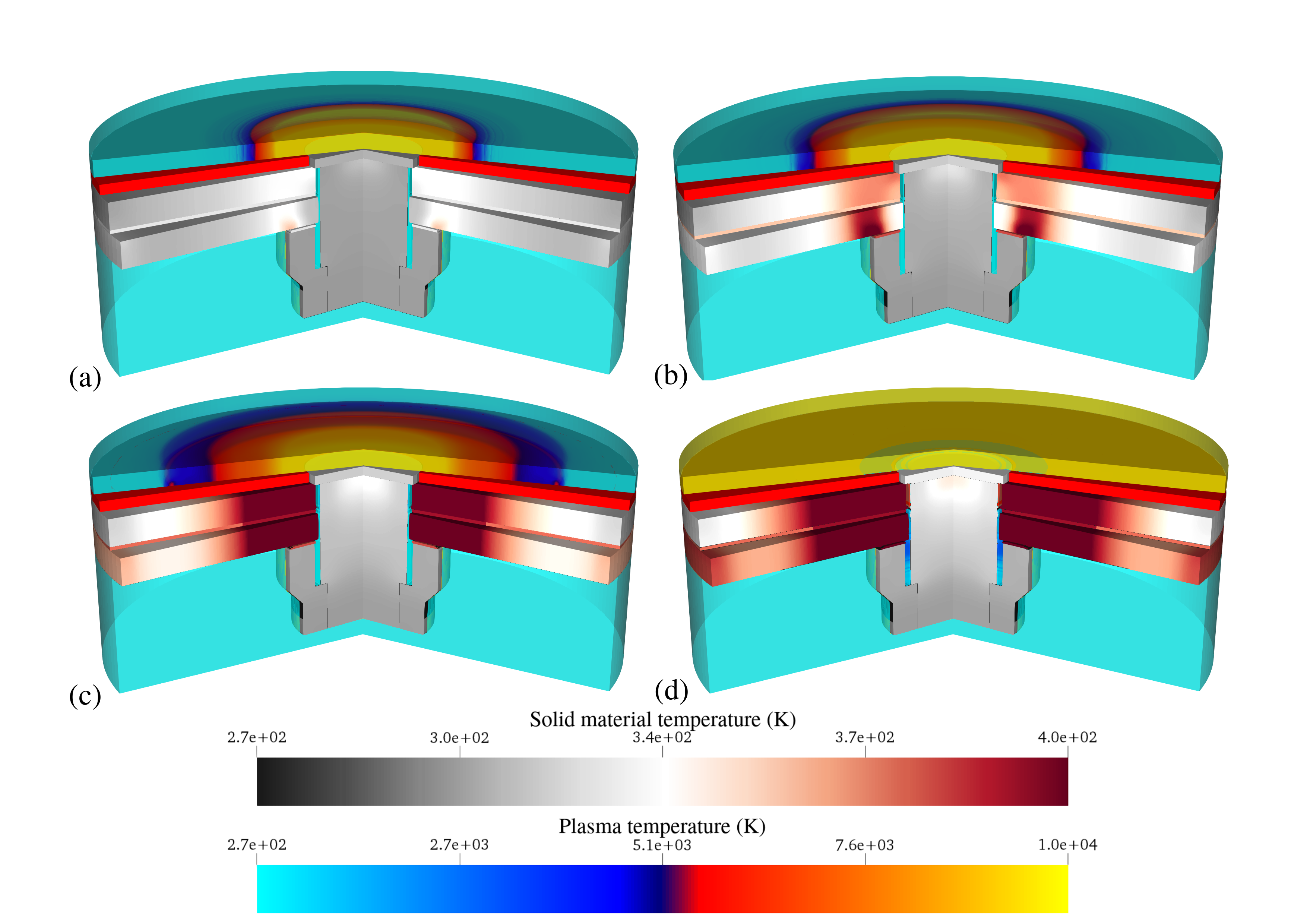
The thermal, mechanical and electrodynamic development of the first fastener configuration over the first 40 s is shown in figure 6, with snapshots shown at 5 s, 10 s, 20 s and 40 s. The increase in the radial extent of the plasma arc is evident, as is the rise and fall in current density in the fastener over time as the current input in the electrode rises and falls according to equation 23. Figure 6 (c) corresponds with the current density streamlines shown in figure 5 (a) .
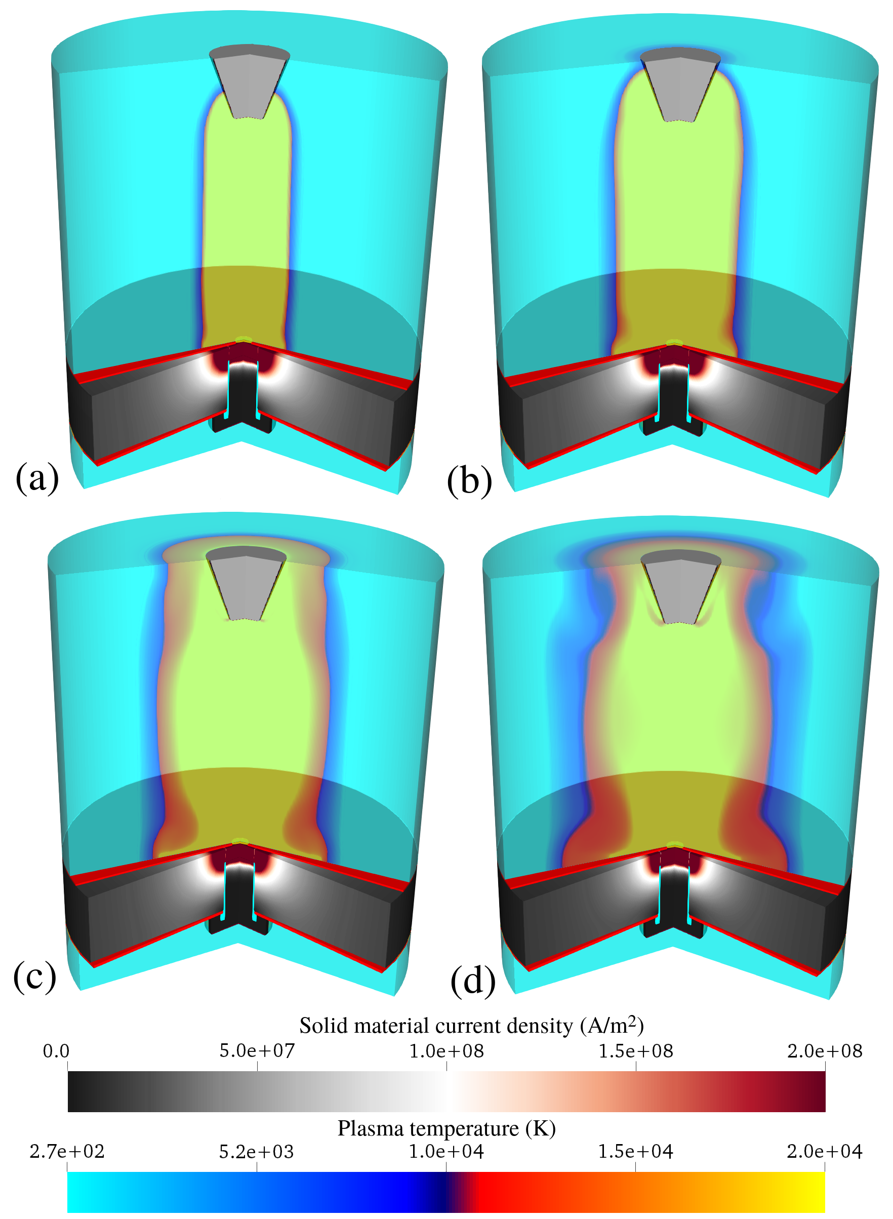
The thermal, mechanical and electrodynamic development of the second fastener configuration over the first 40 s is shown in figure 7, at times directly comparable to figure 6. In this case, figure 7 (c) corresponds with the current density streamline plot shown in figure 5 (b).
The increase in arc radius over time is again evident, as is the difference in arc shape between the two fastener configurations. The current density at the region of direct contact between the fastener bolt and the carbon composite panel remains high throughout the evolution, and this then leads to higher local pressures at the interface between the fastener and panel through increased Joule heating. The interface between the high conductivity titanium fastener and the lower conductivity panel is one area of particular concern in fastener design to reduce the possibility of local breakdown in material integrity. Such behaviour is more likely with the higher current density magnitude over a limited spatial distribution around the upper region of the fastener bolt in the case shown in figure 7, in comparison to figure 6. As this is associated with higher levels of Joule heating and increased pressure rise at the top of the bolt, figures 6 and 7 highlight the advantage of fastener designs that maximise the physical contact area of conductive materials across the fastener-panel interface. This approach is evident in the metallic sleeve designs of Mulazimoglu & Haylock mulazimoglu2011recent .
The analysis in this section is extended in the next section to assess how changes in fastener design can effect the temperature and pressure rise in a gap between the fastener and carbon composite panels. Excessive pressure rise in internal fastener gaps is a potential cause of unwanted outgassing events and electrical sparking in fasteners kirchdoerfer2017 ; kirchdoerfer2018cth ; teulet2017energy .
IV.2 The effect of clearance gap pre-heating
In practice, a fastener assembly may contain internal gaps between, for example, the bolt and the composite panels, or between the bolt and nut. Under the high current input conditions of a lightning strike, ionisation of the gas within the internal voids may occur. Ionisation of the trapped gas can establish an electrically conductive path across the void, which can lead to changes in the current distribution of the assembly and significant increases in the gap pressure. In this section, a method for modelling the development of a conductive path across internal voids is considered and a pre-heating approach to initialise this is investigated.
Building on the initial application of the multi-physics methodology to enable assessment of changing thermal and mechanical behaviour from variations in fastener design and material choice. We now extend this analysis to the internal gap between the fastener bolt, nut and adjacent panel. To enable this extension, a modification is made to the fastener design in the previous section to include a bolt head. It is recognised that in practical fastener designs, a counter-sunk fastener head is often used to enable a flush panel surface and to maximise direct contact with the surrounding substrate. The idealised fastener chosen as an exercise in this section has, however, been designed to limit the direct contact between the fastener bolt and the panel to a region around the bolt head. This is expected to result in a localised region of high current density, with an associated rise in the pressure and temperature through Joule heating. This would therefore make a poor aerospace fastener design in reality but satisfactorily serves here as an idealised model to investigate numerically establishing a conductive path across internal voids. The titanium bolt has a clearance fit with the surrounding panel. The gap is initially assumed to contain air at ambient conditions. In later testing in this section, this assumption is altered with the assumption that electrical breakdown has occurred.
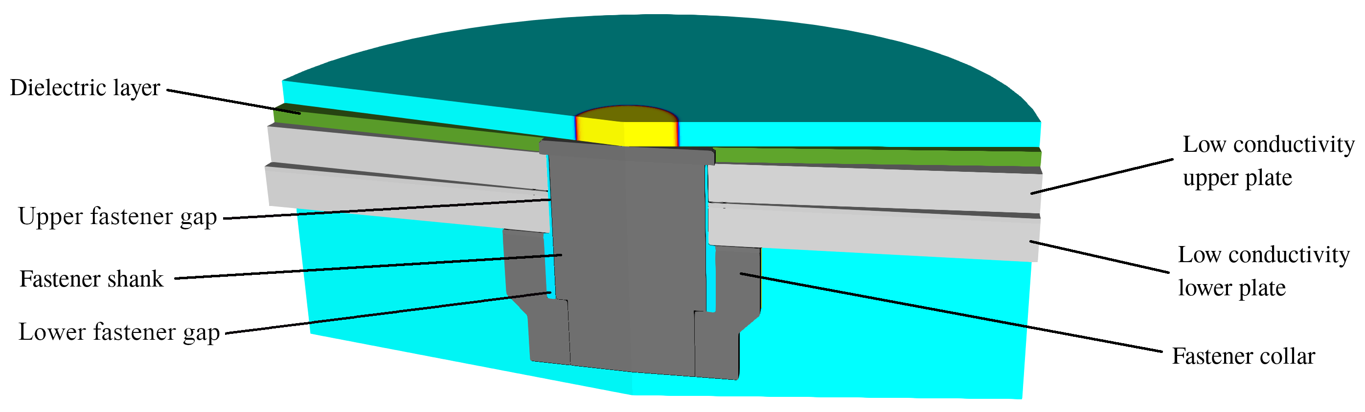
The idealised fastener design used in this section is shown in figure 8. The fastener head is located above two low conductivity panels, sitting flush with the upper surface of a dielectric coating. The titanium fastener has a shank diameter of 6 mm, and this screws into a securing titanium nut (collar) with an outer diameter of 12 mm. Again, in this simplified example the fastener thread detail is not considered. The titanium collar rests on the underside of the lower carbon composite panel, establishing a direct electrical contact between the collar and the lower panel. There is a narrow gap between the fastener and the collar, highlighted as a blue region in figure 8. The width of this gap (0.38 mm) is larger than the gap that exists between the fastener bolt and the carbon composite panel (0.1 mm). The carbon composite substrate is split into two narrower panels, each of thickness 1.7 mm.
The evolution of this system is governed not only by the electrical conductivity of the various components, but also through contact resistance between them. A contact resistance of 1 m is defined between the two carbon composite panels and a further contact resistance region of 1 m is defined between the lower panel and the titanium collar. The contact resistance is taken as a typical value from the literature, as used by, for example Chemartin et al. chemartin2013modeling . In this work it is assumed to be constant. Mastrolembo mastrolembo2017understanding , however, discusses the change in contact resistance that can occur with variations in mechanical loading. In the present fastener configuration, this mechanical loading would relate to the tightening torque of the fastener.
The transient current waveform given by equation 23 is defined along the upper domain boundary and a narrow pre-heated region of the domain at the radial centre is imposed. This pre-heated region is of sufficient temperature (8000 K) for ionisation of the plasma. In this first simulation, the upper and lower fastener gaps are under atmospheric conditions, i.e. there is no initial ionised material present. This is intended to contrast with later simulations in which a pre-heated region is present close to the top of the gap at the start of the computation.
The temperature profiles for the plasma and substrate over the first 40 s in this configuration is shown in figure 9. A high temperature is evident in the low conductivity panels, in contrast to the highly conductive titanium fastener bolt and collar which show little sign of heating. A rise in temperature occurs in both upper and lower panels, highlighting two main current paths; through the fastener bolt head and through direct contact between the collar and lower panel.
Plotting the current density magnitude and streamlines, as shown in figure 10, highlights these two primary current pathways through the fastener geometry. In this preliminary study, only the lower panel is grounded, the current in the upper panel passes to the lower panel at the radial extent of the lower panel. This is visible as a small region of higher current density magnitude at the outer radial edge of the inter-panel region.
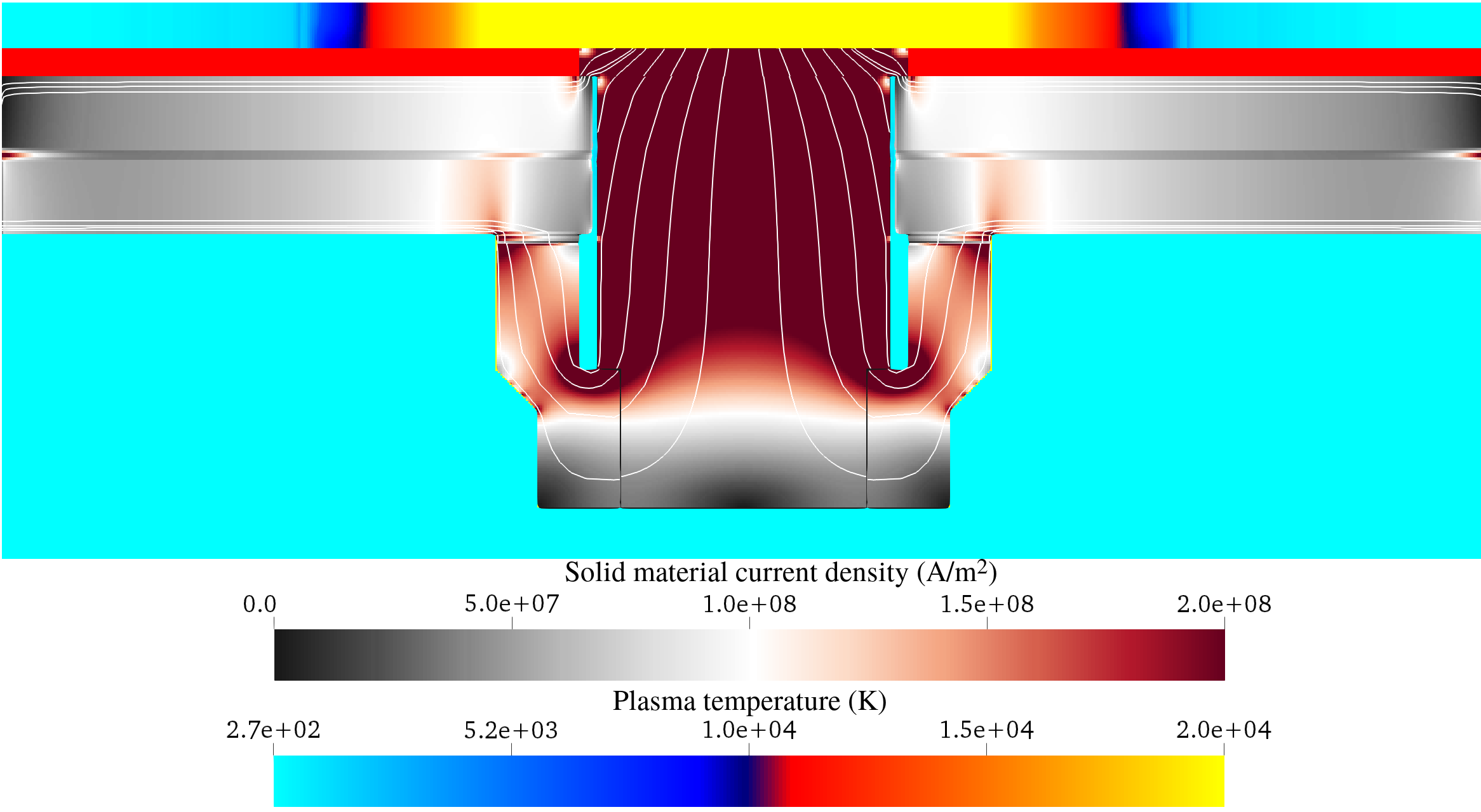
The local increase in current density at the fastener bolt results in a local pressure and temperature rise from Joule heating. Through the multi-material boundary conditions at the interface between the fastener gap and the surrounding materials, this leads to a rise in these properties within the gap itself. This is particularly apparent in the upper-most region of the fastener gap, where conditions are sufficient for ionisation of the confined air to occur. Once this happens, the fastener gap becomes a viable path for current passage between the fastener and the panel.
Although there is a significant increase in temperature of over 5000 K within the fastener gap over the first 40 s, the corresponding rise in plasma pressure in the cavity is markedly below published experimental measurements for comparable configurations. For example, pressures of 25 - 30 MPa (typical) and 70 MPa (peak) are reported in Kirchdoerfer et al. kirchdoerfer2017 for a comparable peak input current, or 24 MPa - 33 MPa for the 10 mm3 volume tested sample in Teulet et al. teulet2017energy .
The behaviour within the fastener gap, shown in figures 9 and 10, assumes that ionisation within this region results only from mechanical effects at the gap interfaces raising temperature and pressure. However, electromagnetic effects can lead to breakdown of the air within this region, and this offer an alternative mechanism for the generation of plasma. Modelling this breakdown is a complex issue and is beyond the scope of this work, however, such behaviour can be approximated by defining a pre-heated region within the fastener gap. This approach is similar to the method used to initialise the plasma arc from the electrode. The necessity to approximate the breakdown of air in this gap is also reported by Kirchdoerfer et al kirchdoerfer2017 , who artificially augment the energy in the gap between a fastener, panel and nut. In the work of Kirchdoerfer et al kirchdoerfer2017 , the energy in the confined gas void is increased through the detonation of a small charge in the fastener gap at a time corresponding to the moment when the local electric field adjacent to the lower panel exceeds the dielectric strength of air, 3 MVm-1. This raises the resulting pressure in the gap, and leads to simulation results which better approximate experimental measurements. It is therefore of interest to establish a conductive path by pre-heating a small section at the top of the gap which may then increase the pressure in the remaining gap over the course of the simulation. Understanding the effect of any approximation to breakdown and the sensitivity this has on the pressure within the gap is important because high pressure close to the bolt-nut interface is considered to result in energetic discharge (outgassing) from an interface of this type. An example configuration with pre-heating within the fastener gap region is shown in figure 11.
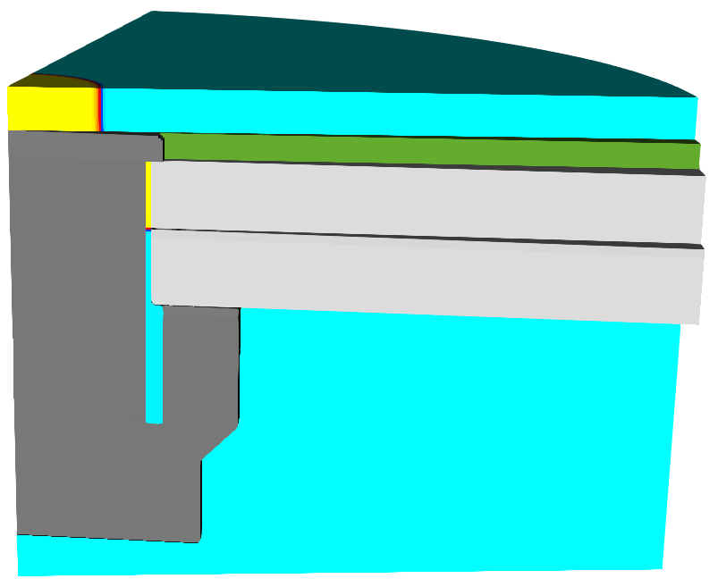
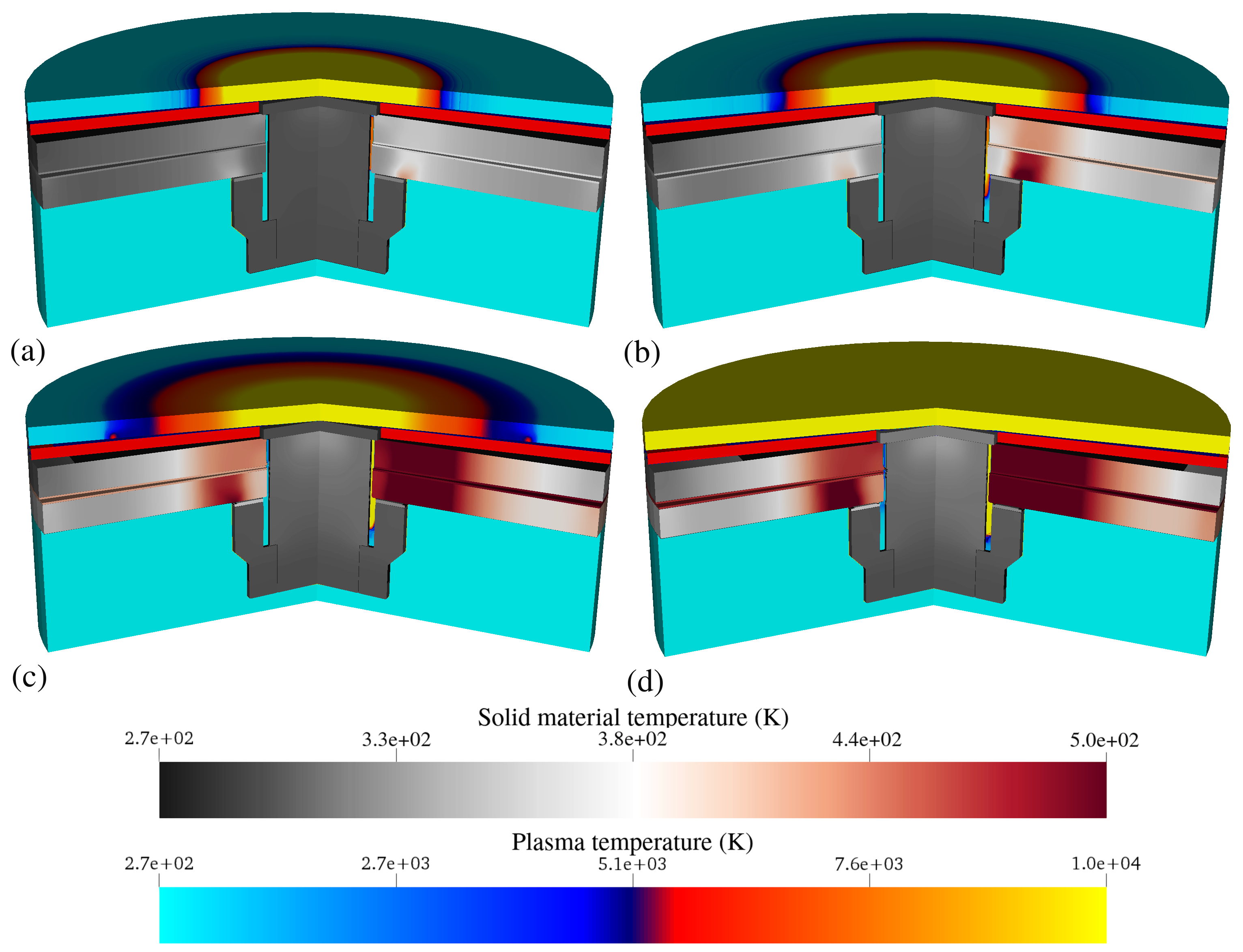
Figure 12 shows a comparison of the temperature profile for configurations with and without a pre-heated gap. The temperature evolution for the fastener configuration with pre-heating is shown as the right-half of each sub-figure, whilst the left-half is the case without, with results reproduced from figure 9. It is clear that the high temperature region in the upper section of the fastener gap, results in significant evolution of the material in this gap, filling much of it with plasma. This evolution slows at later times as it expands into the larger volume collar gap. Temperatures in this region are sufficient for a partially ionised plasma to form, hence electrical conductivity increases to provide a new current pathway between the fastener and the surrounding carbon composite panels. The current passage through the plasma in the gap consequently increases the temperature and pressure.
In addition to the evolution within the fastener gap, there is also an increase in temperature in the carbon composite panels for the pre-heated case. This is due to direct energy deposition in the panels, since ionised material in the fastener gap provides a highly conductive path for the majority of the current to flow.
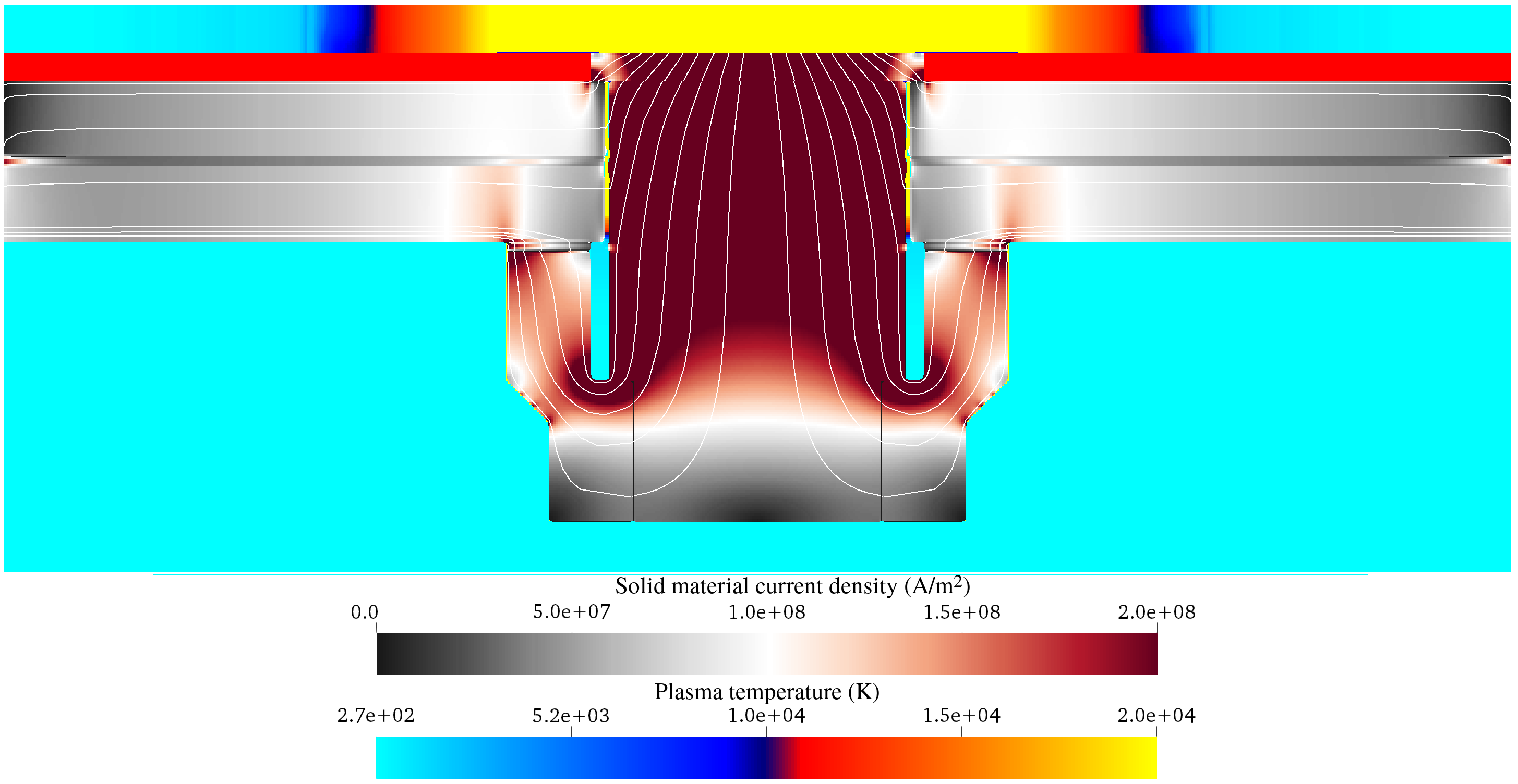
Figure 13
shows the current streamlines flowing through the panels.
This can be compared with the case without pre-heating in figure 10, where current
flow is restricted to the top of the upper panel and the bottom of the
lower panel. The electrical conductivity in the plasma gap at this time
is still lower than the electrical conductivity in the titanium
fastener and shank, hence a significant proportion of the current
still passes through the fastener shank, nut and lower side of the
carbon composite panel, and directly between the fastener head and the
upper side of the carbon composite panel. The addition of a viable path
in figure 13 across
the fastener gap further raises the plasma temperature, pressure and electrical
conductivity, reinforcing this route for current flow.
.
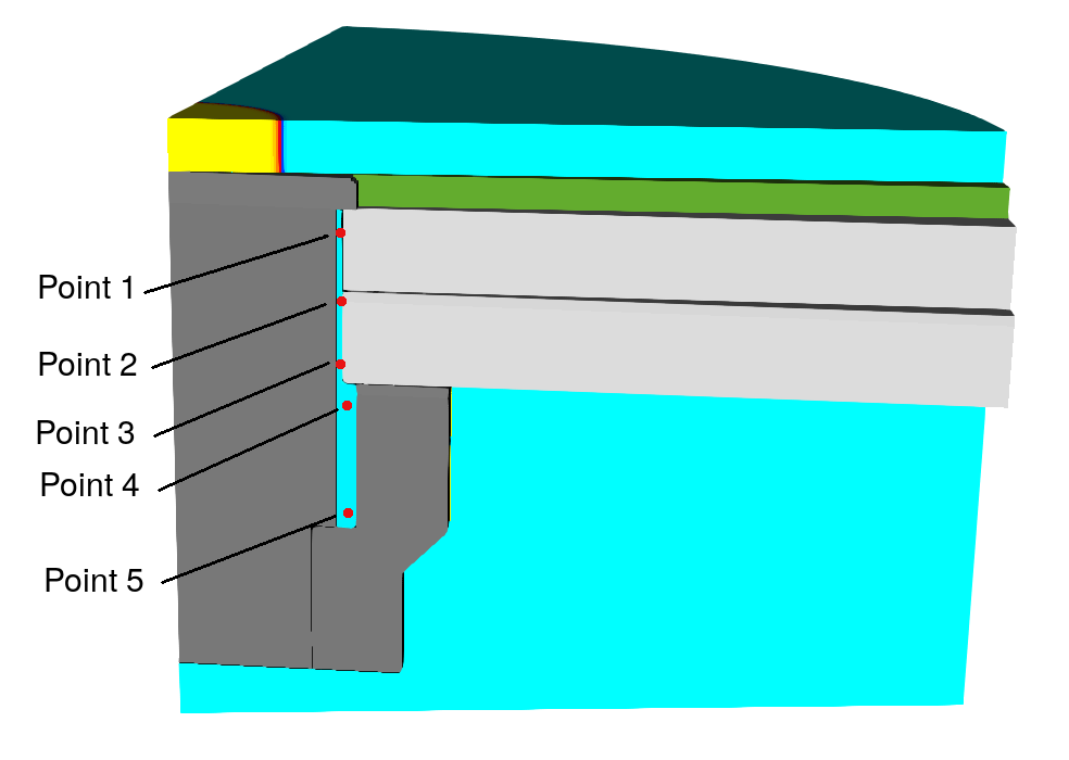
The behaviour of the material in the fastener gap can be monitored over the course of the simulation by defining data collection points. Five fixed spatial points are illustrated in figure 14. Three of these points monitor behaviour in the narrow section of the fastener gap and two further data points are located in the wider cavity between the fastener bolt and collar. The temperature over the first 100 s is shown for each of these locations in figure 15.
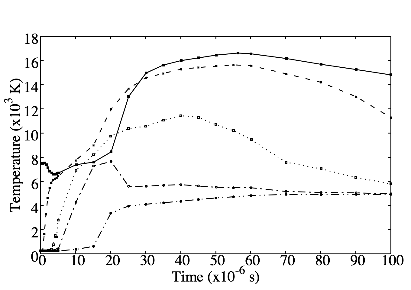
The temperature at the highest location, point 1, in figure 15 rises gradually from the pre-heated temperature over the first 20 s. This is then accompanied by a rapid rise in temperature between 20 s and 40 s as this region becomes a viable current path. The temperature continues to increase to 60 s, after which the reduction in input current and the expansion in to the wider gap between the fastener and collar results in a drop in temperature. Points 2-5, are initially located just outside the pre-heated region, hence the material here is initially under ambient conditions. The initial discontinuity between the pre-heated and ambient regions results in a shock wave which travels along the fastener gap, raising the pressure and temperature in the lower fastener gap region. This is visible through the initial rise in temperature at points 2 and 3, and also in the initial decrease in temperature at point 1 over the first 5 s. After this time, the current flow through the material is the dominant cause of evolution, and the temperature continues to rise, with point 2 reaching a peak value of 1540 K at 55 s. The subsequent decrease in temperature at point 2 is greater than for point 1, falling to 1200 K at a time of 100 s, whilst point 1 falls to 1420 K. Point 3 shows a similar temperature profile though the rise in temperature from ambient conditions occurs later than at point 2. Figure 15 also shows that the peak temperature at point 3 is again lower than for the two higher locations, rising to 1145 K at 40 s. The two points inside the larger collar cavity, points 4 and 5, appear to be outside the main current path, with the rise in temperature in this region largely due to flow from the higher temperature regions above. This continued movement from the upper cavity region to the lower region causes the temperature at the lowest point, point 5, to continue to increase over the entire course of the simulation, though the final temperature here remains considerably lower than the upper four points. This gradient highlights the difference in gap temperature (and hence pressure) that can result from the existence of a viable current path across only part of the fastener gap. In the next section, the data collection points are used to investigate how the pressure in the gap changes with alterations in the width of the narrow fastener gap.
IV.3 The effect of clearance gap size
One of the contributory factors in outgassing and thermal sparking from fastener joints is considered to be the pressure rise in the collar gap. Understanding the role of gap size on the pressure rise close to the interface is therefore important for guiding design choices. The present numerical approach can be used to investigate the effects of geometry-related changes in pressure within the fastener gap.
Using configurations similar to those presented in section IV.2, the effect of changing the radial distance between the fastener bolt and the carbon composite panel is considered, for pre-heated and non pre-heated fastener gaps. Seven cases are considered, with the distance between fastener and panels referred to as the ‘shank gap’. The larger gap, between the fastener and the collar, is termed the ‘collar gap’ in this section and is kept constant throughout. The shank gap is varied between 50 m and 200 m. All other parameters, including the larger collar gap and the panel thickness, are kept the same.
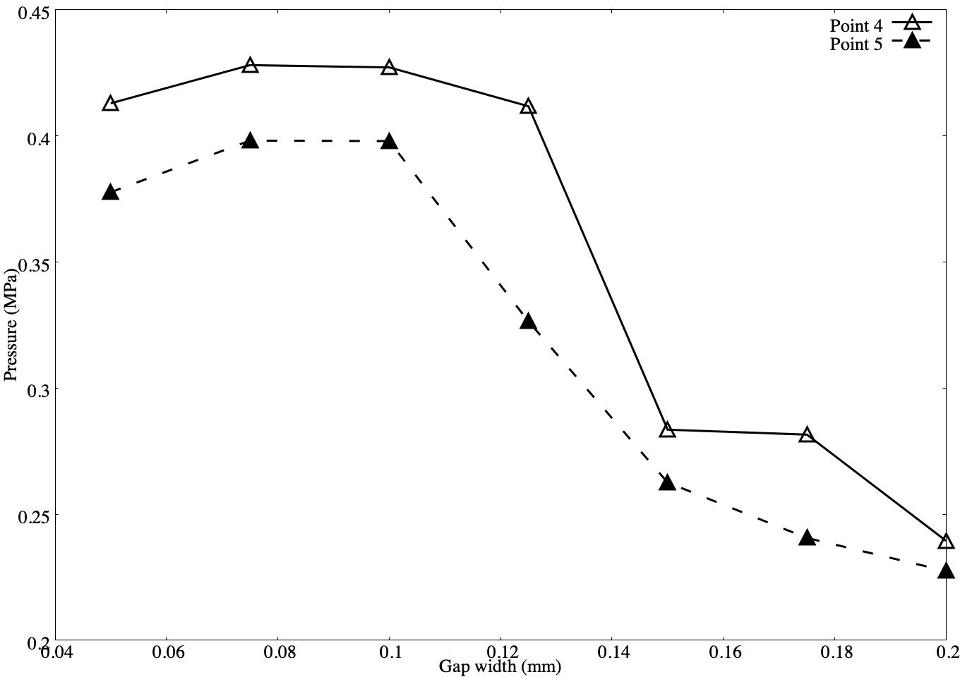
The key region at which outgassing is likely to occur is where the collar meets the carbon composite panel, hence the primary interest in this study is to compare the pressure rise at data collection points 4 and 5, as identified in figure 14. Figure 16 shows the pressure at these two points after 100 s for the case without pre-heating. This time is chosen to allow the pressure evolution to equilibrate between the collar and shank gaps. The pressure is shown to vary significantly with the width of the shank gap, though in all cases the pressure at point 4 (the higher of the two locations) remains greater than at point 5. The pressure decreases sharply at point 5 above a shank gap width of 0.1 mm, though it remains high at this width for point 4. This may indicate a reduction in flow from the upper to the lower region of the shank gap. The subsequent reduction in pressure at both data point locations for wider shank gaps highlights the decrease in electrical conductivity at the top of the gap. It is also noted that for all shank gap widths, the pressure is about two orders of magnitude below those cited in experiments.
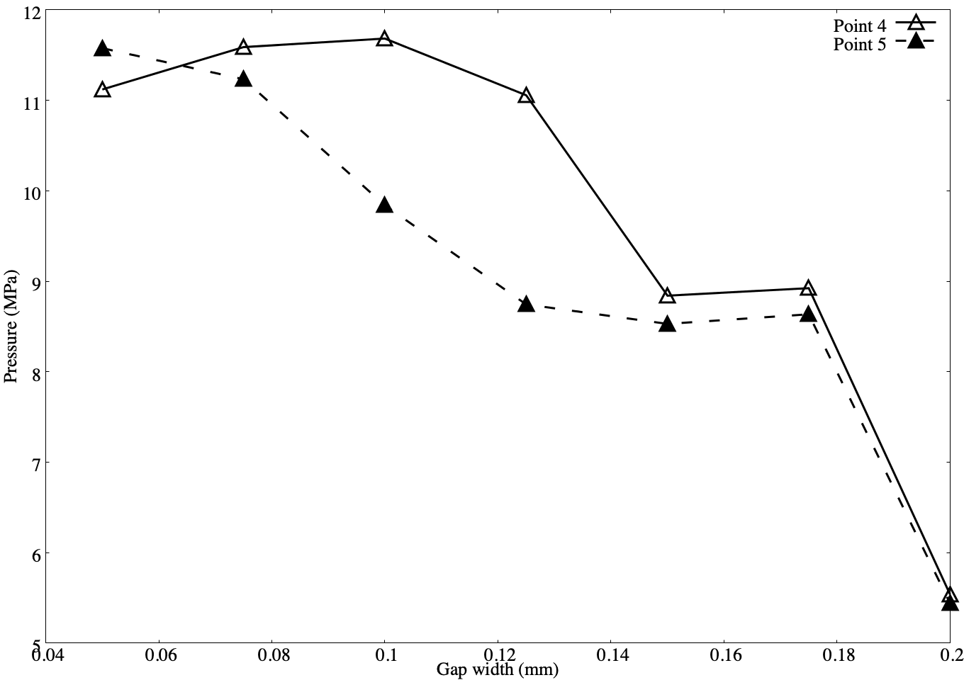
Figure 17 shows the pressure at points 4 and 5 after 100 s for varying shank gap width where the upper region of the shank gap has been pre-heated. In all cases, the pressures at both points are significantly greater than those without pre-heating, in figure 16. In this case, a maximum pressure of 11.8 MPa occurs at point 4 for the 0.1 mm shank gap width. Interestingly, for the narrowest shank gap, 0.05 mm, the pressure at point 5 is greater than that at point 4. This is not mirrored in any of the other gap widths and may be associated with a greater penetration of the high temperature fluid from the shank gap into the collar gap. A similar trend to that shown in figure 16, with pressure decreasing as shank gap width increases is observed in figure 17. Again, the drop in pressure resulting from the increasing shank gap width at point 4 lags behind that of point 5. From analysis of the corresponding pressure traces in the shank gap, this decrease in pressure appears to be predominantly associated with a decrease in the length of time over which the electrical conductivity in the upper regions of the shank gap is sufficiently high for the fastener gap to remain a viable current path.
The results in this section demonstrate that the multi-physics methodology outlined in this paper is capable of computing the effect of transient changes in current flow through a fastener geometry on the pressure and temperature within the substrate materials, and in gas-filled voids. These results also indicate that this approach is capable of accounting for the influence of geometric changes on the current distribution and associated thermal and mechanical fastener behaviour. The increase in temperature and pressure in the pre-heated gas results further highlights the influence of gas-filled gaps on the electrical and thermal development of the fastener as a whole.
The importance of considering direct lightning attachment in fastener design is highlighted by the simulations presented in this paper. Understanding the path taken by the current through the fastener geometry can lead to judicious use of dielectric layers to manipulate the current path. Potentially this can mean directing the current away from electrically sensitive components, minimising indirect attachment to remote components, or reducing the possibility of energetic discharge, thermal sparking and edge glow. The simulations in this paper also provide confirmation of existing best practice, that to minimise the possibility of outgassing, the fastener design should maximise the electrical contact between fastener components. This, in turn, minimises the contact resistance and reduces the potential for ionisation of the gas-filled gaps between components. Sections IV.2 and IV.3 suggest that the plasma heating and mass transport characteristics in regions of confined plasma can be influenced by the size, shape and relative location of internal voids. The simulations presented in this work also suggest that convective transport of the hot plasma can lead to a pressure rise in connected void regions away from the direct current path.
V Conclusions
This paper presents a multi-physics methodology that provides dynamic, non-linear coupling of a plasma arc with an elastoplastic multi-material model description of an aerospace fastener assembly. This methodology simultaneously solves hyperbolic partial differential equations for each material to achieve a two-way coupled system between the plasma arc and the fastener materials. The advantage of this approach is that the transient changes in the mechanical and electrodynamic properties for each material, and their associated influence on the surrounding materials, are captured.
The ability for the numerical model to capture the dynamic influence of changes in material choice, and layering design, on the electrical current path and associated thermal and mechanical properties is demonstrated. This highlights how a non-judicious use of dielectric layers and the presence of unsealed internal gaps in the fastener design may result in conditions such that structural and sparking issues could occur under a transient, high current event. Joule heating of the substrate materials in these regions can result in high local stresses and material temperatures. Large potential differences across internal gas-filled voids can cause ionisation and the promotion of a high pressure plasma which is considered to be a driving mechanism for energetic discharge from fasteners through sparking. The inclusion of simple contact resistances in the numerical model accounts for surface roughness, fibre ply pull-out and other surface imperfections between fastener components. This could be extended to include dynamically changing contact resistances to account for transient changes in the mechanical and thermal loading of components over the course of the lightning strike.
Additionally, the model presented in this work could be extended to include a statistical approximation to the microscopic surface imperfections that exist at the contact surface between adjacent materials. This would allow additional mechanisms for energetic discharge to be studied, in particular thermal sparking, as detailed by Odam et al. odam1991lightning ; odam2001factors . Incorporating a fully anisotropic equation of state for composite materials, for example the method of Lukyanov lukyanov2010equation , would allow for directionally-dependent effects to be studied.
The flexibility of the numerical model for undertaking parameter studies is demonstrated with an example in which the dimensions of an internal gap between fastener components is systematically altered. This paper is intended to tentatively highlight the potential for the multi-physics methodology to be used as an engineering tool in the design and optimisation of aerospace components subject to plasma arc attachment, or as a developmental aid in experiment design.
Acknowledgements
The authors acknowledge the funding support of Boeing Research & Technology (BR&T) through project number SSOW-BRT-L0516-0569. The authors would also like to thank Micah Goldade, Philipp Boettcher and Louisa Michael of BR&T for technical input throughout this work.
References
- [1] Andrey E Krauklis, Christian W Karl, Abedin I Gagani, and Jens K Jørgensen. Composite material recycling technology—state-of-the-art and sustainable development for the 2020s. Journal of Composites Science, 5(1):28, 2021.
- [2] Laurent Chemartin, Ph Lalande, B Peyrou, A Chazottes, PQ Elias, C Delalondre, BG Cheron, and F Lago. Direct effects of lightning on aircraft structure: analysis of the thermal, electrical and mechanical constraints. AerospaceLab, (5):p–1, 2012.
- [3] Simon Evans. Characterisation of outgassing from carbon fibre composite aircraft joints subjected to lightning current. PhD thesis, Cardiff University, 2018.
- [4] GA Odam, AW Hanson, and RH Evans. Lightning protection requirements for aircraft-a proposed specification (revised issue 1). Technical report, Royal Aerosopace Establishment Farnborough (United Kingdom), 1991.
- [5] GAM Odam, JR Tilston, and CCR Jones. Factors affecting fuel system certification against lightning hazards. SAE transactions, pages 393–406, 2001.
- [6] Ivan Revel, Simon Evans, and Franck Flourens. Edge glow: a combined voltage/power controlled mechanism? In 2016 33rd International Conference on Lightning Protection (ICLP), pages 1–6. ICLP, 2016.
- [7] Eddie Kwon and Arthur C Day. Optical spark mode discriminator methods and systems, April 7 2009. US Patent 7,515,263.
- [8] SJ Haigh, CJ Hardwick, and RE Baldwin. Measurements of some parameters of thermal sparks with respect to their ability to ignite aviation fuel/air mixtures. In The 1991 International Aerospace and Ground Conference on Lightning and Static Electricity, volume 2, page 10, 1991.
- [9] S. Haigh, R. Crook, and N. Terzino. The use and calibration of digital camera systems in fuel tank testing. In International Conference on Lightning and Static Electricity. ICOLSE, 2013.
- [10] Hasim Mulazimoglu and Luke Haylock. Recent developments in techniques to minimize lightning current arcing between fasteners and composite structure. In International Conference on Lightning and Static Electricity, volume 20, 2011.
- [11] Toshio Ogasawara, Yoshiyasu Hirano, and Akinori Yoshimura. Coupled thermal–electrical analysis for carbon fiber/epoxy composites exposed to simulated lightning current. Composites Part A: Applied Science and Manufacturing, 41(8):973–981, 2010.
- [12] Gasser Abdelal and A Murphy. Nonlinear numerical modelling of lightning strike effect on composite panels with temperature dependent material properties. Composite Structures, 109:268–278, 2014.
- [13] Yunli Guo, Qi Dong, Jingliang Chen, Xueling Yao, Xiaosu Yi, and Yuxi Jia. Comparison between temperature and pyrolysis dependent models to evaluate the lightning strike damage of carbon fiber composite laminates. Composites Part A: Applied Science and Manufacturing, 97:10–18, 2017.
- [14] Qi Dong, Yunli Guo, Xiaochen Sun, and Yuxi Jia. Coupled electrical-thermal-pyrolytic analysis of carbon fiber/epoxy composites subjected to lightning strike. Polymer, 56:385–394, 2015.
- [15] FS Wang, N Ding, ZQ Liu, YY Ji, and ZF Yue. Ablation damage characteristic and residual strength prediction of carbon fiber/epoxy composite suffered from lightning strike. Composite Structures, 117:222–233, 2014.
- [16] Z.Q. Liu, Z.F. Yue, F.S. Wang, and Y.Y. Ji. Combining analysis of coupled electrical-thermal and blow-off impulse effects on composite laminate induced by lightning strike. Applied Composite Materials, 22(2):189–207, 2015.
- [17] Yeqing Wang and Crystal L Pasiliao. Modeling ablation of laminated composites: A novel manual mesh moving finite element analysis procedure with ABAQUS. International Journal of Heat and Mass Transfer, 116:306–313, 2018.
- [18] Shintaro Kamiyama, Yoshiyasu Hirano, and Toshio Ogasawara. Delamination analysis of CFRP laminates exposed to lightning strike considering cooling process. Composite Structures, 196:55–62, 2018.
- [19] Shintaro Kamiyama, Yoshiyasu Hirano, Takao Okada, Koji Sawaki, Takeo Sonehara, and Toshio Ogasawara. Damage behavior of CFRP subjected to simulated lightning current under air, reduced-pressure air, and N2 environments. Composite Structures, 230:111519, 2019.
- [20] Kunkun Fu and Lin Ye. Modelling of lightning-induced dynamic response and mechanical damage in CFRP composite laminates with protection. Composite Structures, 218:162–173, 2019.
- [21] S.J. Evans, S. Hellsten, and M. Cole. A review of computational modelling tools for lightning direct effects simulation. In ICOLSE, 2011.
- [22] F. Tholin, L. Chemartin, and P. Lalande. Numerical investigation of the interaction of a lightning and an aeronautic skin during the pulsed arc phase. IET Conference Proceedings, pages 39 (6 .)–39 (6 .)(1), January 2015.
- [23] SLJ Millen, A Murphy, G Abdelal, and G Catalanotti. Sequential finite element modelling of lightning arc plasma and composite specimen thermal-electric damage. Computers & Structures, 222:48–62, 2019.
- [24] T. Kirchdoerfer, A. Liebscher, H. Mulazimoglu, and M Ortiz. shock physics simulation of pressure, temperature and combustion within an aerospace carbon fiber panel fastener assembly due to direct lightning attachment. 2017.
- [25] T Kirchdoerfer, A Liebscher, and M Ortiz. CTH shock physics simulation of non-linear material effects within an aerospace CFRP fastener assembly due to direct lightning attachment. Composite Structures, 189:357–365, 2018.
- [26] R. S. Martins. Étude expérimentale et théorique d’un arc de foudre et son interaction avec un matériau aéronautique. PhD thesis, Université Paris-Saclay, 2016.
- [27] Stephen Millmore and Nikolaos Nikiforakis. Multi-physics simulations of lightning strike on elastoplastic substrates. arXiv preprint arXiv:1906.08521, 2019.
- [28] Louisa Michael, Stephen T Millmore, and Nikolaos Nikiforakis. A multi-physics methodology for four-states of matter. arXiv preprint arXiv:1905.06620, 2019.
- [29] Frederik Träuble, ST Millmore, and Nikolaos Nikiforakis. An improved equation of state for air plasma simulations. Physics of Fluids, 33(3):036112, 2021.
- [30] A. D’angola, G. Colonna, C. Gorse, and M. Capitelli. Thermodynamic and transport properties in equilibrium air plasmas in a wide pressure and temperature range. The European Physical Journal D, 46(1):129–150, 2008.
- [31] P. T. Barton, D. Drikakis, E. Romenski, and V.A. Titarev. Exact and approximate solutions of riemann problems in non-linear elasticity. Journal of Computational Physics, 228(18):7046 – 7068, 2009.
- [32] Stefan Schoch, Kevin Nordin-Bates, and Nikolaos Nikiforakis. An eulerian algorithm for coupled simulations of elastoplastic-solids and condensed-phase explosives. Journal of Computational Physics, 252:163–194, 2013.
- [33] Stefan Schoch, Nikolaos Nikiforakis, and Bok Jik Lee. The propagation of detonation waves in non-ideal condensed-phase explosives confined by high sound-speed materials. Physics of Fluids, 25(8):086102, 2013.
- [34] S. K. Godunov and I. Romenskii, E. Nonstationary equations of nonlinear elasticity theory in eulerian coordinates. Journal of Applied Mechanics and Technical Physics, 13(6):868–884, 1972.
- [35] G. H. Miller and P. Colella. A high-order eulerian godunov method for elastic–plastic flow in solids. Journal of computational physics, 167(1):131–176, 2001.
- [36] Philip T. Barton and Dimitris Drikakis. An eulerian method for multi-component problems in non-linear elasticity with sliding interfaces. Journal of Computational Physics, 229(15):5518 – 5540, 2010.
- [37] Philip Trevor Barton, Dimitris Drikakis, and EI Romenski. An eulerian finite-volume scheme for large elastoplastic deformations in solids. International journal for numerical methods in engineering, 81(4):453–484, 2010.
- [38] Alexander A Lukyanov. An equation of state of a carbon-fibre epoxy composite under shock loading. The European Physical Journal B-Condensed Matter and Complex Systems, 74(1):35–45, 2010.
- [39] George A. Christou, Laurence R. Young, Rahul Goel, Andrew P. Vechart, and Antoine Jérusalem. Shock attenuation of PMMA sandwich panels filled with soda-lime glass beads: A fluid-structure interaction continuum model simulation. International Journal of Impact Engineering, 47(0):48 – 59, 2012.
- [40] Toru Hamada, Yuichi Nakamura, and Shigeru Itoh. The performance of pressure vessel using concentric double cylindrical high explosive. Journal of pressure vessel technology, 126(4):409–413, 2004.
- [41] S. K. Sambasivan and H. S. UdayKumar. Ghost fluid method for strong shock interactions part 1: Fluid-fluid interfaces. Aiaa Journal, 47(12):2907–2922, 2009.
- [42] Frank Losasso, Tamar Shinar, Andrew Selle, and Ronald Fedkiw. Multiple interacting liquids. ACM Transactions on Graphics (TOG), 25(3):812–819, 2006.
- [43] Hans Petter Langtangen and Anders Logg. Solving PDES in minutes-the fenics tutorial volume i, 2016.
- [44] L Chemartin, Ph Lalande, C Delalondre, B Cheron, and F Lago. Modelling and simulation of unsteady dc electric arcs and their interactions with electrodes. Journal of Physics D: Applied Physics, 44(19):194003, 2011.
- [45] Anders Larsson, Philippe Lalande, Anne Bondiou-Clergerie, and Alain Delannoy. The lightning swept stroke along an aircraft in flight. part i: thermodynamic and electric properties of lightning arc channels. Journal of Physics D: Applied Physics, 33(15):1866, 2000.
- [46] ARP SAE. Aircraft Lightning Environment and Related Test Waveforms, jan 2013.
- [47] Philippe Teulet, Tommy Billoux, Yann Cressault, Mathieu Masquère, Alain Gleizes, Ivan Revel, Bruno Lepetit, and Gilles Peres. Energy balance and assessment of the pressure build-up around a bolt fastener due to sparking during a lightning impact. The European Physical Journal Applied Physics, 77(2):20801, 2017.
- [48] L Chemartin, P Lalande, and F Tristant. Modeling and simulation of sparking in fastening assemblies. In ICOLSE 2013, 2013.
- [49] Giuseppe Mastrolembo. Understanding and Optimising Parameters for Lightning Strike Testing of CFRP Materials. PhD thesis, Cardiff University, 2017.