qTask: Task-parallel Quantum Circuit Simulation with Incrementality
Abstract
Incremental quantum circuit simulation has emerged as an important tool for simulation-driven quantum applications, such as circuit synthesis, verification, and analysis. When a small portion of the circuit is modified, the simulator must incrementally update state amplitudes for reasonable turnaround time and productivity. However, this type of incrementality has been largely ignored by existing research. To fill this gap, we introduce a new incremental quantum circuit simulator called qTask. qTask leverages a task-parallel decomposition strategy to explore both inter- and intra-gate operation parallelisms from partitioned data blocks. Our partitioning strategy effectively narrows down incremental update to a small set of partitions affected by circuit modifiers. We have demonstrated the promising performance of qTask on QASMBench benchmarks. Compared to two state-of-the-art simulators, Qulacs and Qiskit, qTask is respectively 1.46 and 1.71 faster for full simulation and 5.77 and 9.76 faster for incremental simulation.
I Introduction
Quantum computing (QC) is a promising computing paradigm for tackling certain types of problems that are classically intractable, such as cryptography, chemistry simulation, and finance [1]. Among various QC applications, classical quantum circuit simulation (QCS) is essential for researchers to understand quantum operations, design quantum algorithms, and validate quantum circuit functionality [2]. However, QCS is extremely challenging because it demands large computation and memory to evaluate state amplitudes of qubits. For example, a full simulation of an -qubit circuit requires an exponential size of vector to store amplitudes, as a result of superposition. To tackle this challenge, QCS researchers have explored parallel computing [3, 4], data compression [2], circuit optimization [5, 6], etc.
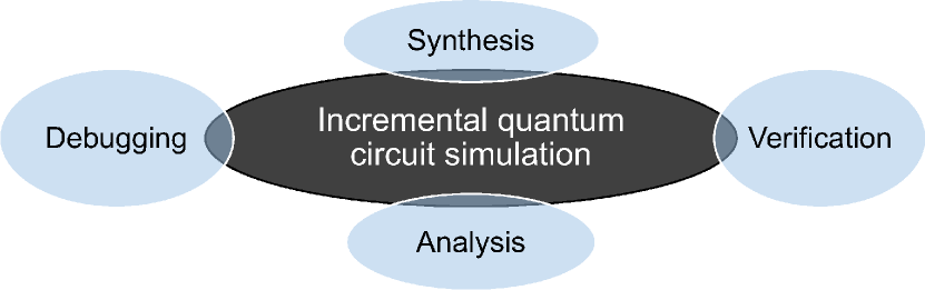
Despite the rapid growth of QCS research, existing simulators are largely short of a key feature–incrementality. Incremental QCS has recently emerged as an important tool for simulation-driven QC applications, as shown in Figure 1. For example, quantum circuit synthesizers can iteratively modify circuit gates to increase certain state probability and verify the results with thousands of simulation runs [7, 8, 9, 10]; developers can issue step-by-step simulation calls to debug how qubits change during the implementation of quantum algorithms; equivalence checking tools can repetitively add or remove gates to verify how similar two circuits are based on simulation results [11]. For these applications, when small portions of a quantum circuit is modified, re-simulating the full circuit is infeasible from a turnaround time and productivity perspective. The simulator must incrementally update only affected regions and ensure state integrity in an efficient manner.
There are several challenges for designing an efficient incremental QCS system. First, running QCS in a static environment is very different from a dynamic environment. When a quantum circuit begins to change, it can become very difficult to reorganize data structures and keep algorithmic invariants consistent over incremental operations. Second, achieving fast incremental QCS requires very strategic task partitioning to make the most of parallelism [12]. When applications modify the circuits, we need to quickly identify affected partitions and restructure their task dependencies for incremental update. Last but not least, although algorithms of incrementality have been widely studied in the classical design flow of digital circuits (e.g., incremental timing/power analysis [13, 14]), we cannot directly reuse them due to distinct behavior of quantum circuits, such as superposition and entanglement.
To overcome these challenges, we introduce qTask, a state vector-based quantum circuit simulator that efficiently supports incrementality using task parallelism. To the best knowledge of authors, qTask is the first incremental quantum circuit simulator in the literature. Our result can largely benefit many simulation-driven quantum applications. We summarize our technical contributions as follows:
-
•
We present a lightweight C++ programming model to support incremental QCS. Applications can use our circuit modifiers to modify existing quantum circuits and call state update to transparently perform incremental simulation.
-
•
We present a task graph-based partitioning strategy to explore both inter- and intra-gate operation parallelisms from a quantum circuit. Our strategy parallelizes both full simulation and incremental simulation.
-
•
We present an efficient technique to maintain invariants of our task partitioning over sequences of circuit modifiers. When a state update call is issued, we can quickly identify affected partitions and restructure the task graph to re-simulate state amplitudes incrementally.
We have evaluated the performance of qTask on a set of medium- and large-scale circuits in QASMBench [15], an OpenQASM benchmark suite for noisy intermediate-scale quantum (NISQ) evaluation and simulation. Compared to two state-of-the-art simulators, Qulacs [3] and Qiskit [16], qTask is respectively 1.46 and 1.71 faster for full simulation and 5.77 and 9.76 faster for incremental simulation. We believe qTask stands out as a unique system given the ensemble of software tradeoffs and architectural decisions we have made.
II Background and Related Work
In this section, we give an overview of quantum computation and related work on QCS. Then, we discuss the importance of incremental QCS and its challenges.
II-A Quantum Circuits and Simulation
A quantum circuit of qubits is a sequence of quantum gates that act on quantum states. Each state is a superposition or a linear combination of possible binary states using amplitudes, denoted as . For brevity, binary states can be written in decimal, . Squared amplitudes are probability of individual states to which a superposition state will collapse when measurement is performed. Thus, squared amplitudes need to sum up to 1.
Industrial quantum computers use a set of standard single-qubit gates and two-qubit controlled gates to perform universal computation [15]. These standard gates are defined by or unitary matrices and can compose larger gates, such as Toffoli, Fredkin, and controlled rotators. The following example shows the standard Pauli-X gate, Hadamard gate, and controlled-NOT (CNOT) gate in matrix form. Notice that NOT and X are interchangeable in gate naming.
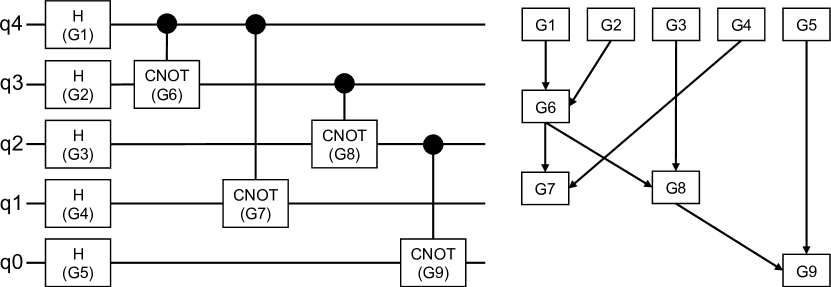
A collection of quantum gates at a level forms a unitary transformation matrix defined by the Kronecker product () of individual gate matrices from the first qubit to the -th qubit. Figure 2 shows a five-qubit circuit with five Hadamard gates and four CNOT gates. The first five Hadamard gates form the transformation matrix, , to create superposition. The last four CNOT gates create entanglement. Finding unitary transformation matrices is an integral part of QCS. First, we order the gates left to right and pad an empty spot with an identity matrix of an appropriate dimension. Parallel gates can be ordered arbitrarily, for instance, G7 and G8. Then, we find all matrices via Kronecker product and multiply them in order. The resulting matrix represents the entire circuit and can be multipled by input state vectors to derive output states. Such simulations allow researchers and developers to evaluate the complexity of new quantum algorithms and validate quantum devices.
II-B Existing Quantum Circuit Simulators
Mainstream QCS software is based on two paradigms, state vector and tensor network contraction. State vector-based QCS keeps a vector of the current state and iteratively multiplies it by a state transformation matrix. To improve space and time efficiency, researchers have proposed various techniques, such as compact binary decision diagram (BDD) to represent matrices [17], lossy data compression to trade accuracy for space [2], multi-threaded sparse matrices [3], graphics processing units (GPUs) to gain throughput performance [18, 19], and distributed vector to scale out computation [20, 21]. While being mathematically simple, state vector has been widely used in mainstream simulators including commercial tools (IBM Qiskit [16], MS QDK [22], Google Qsim [23]).
On the other hand, tensor network-based QCS represents a quantum circuit in a tensor network and explores the best contraction order for state update. However, the time and space costs for contracting tensor networks are exponential with the network width. Therefore, existing research has been targeting low-depth circuits using various optimization techniques, such as slicing window with asynchronous task parallelism [24, 25], GPU acceleration [19], and tree partitioning [26]. While computing tensor networks is efficient, such an organization does not support intermediate measurement [2]. Furthermore, tensor network is primarily optimized for static environments. When a circuit begins to change, maintaining a dynamic tensor network becomes very challenging.
In addition to state vector and tensor network, general-purpose heuristics for improving simulation efficiency have also been studied, such as gate cancelling [4], gate restriction [27], gate reordering [18], pattern matching [5], approximation [28], and so on. Many of these strategies focus on removing redundancy in a quantum circuit or restructuring it to gain a more compact representation under certain assumptions.
II-C Importance and Challenges of Incrementality
As for the rapid growth of quantum software development, incremental QCS has emerged as an important tool for the success of many simulation-driven QC applications [9]. For instance, quantum circuit synthesis engines can issue thousands of simulation runs in an optimization loop to evaluate how a local change (e.g., qubit swapping, rotation degree turning, gate insertion and removal) affects output amplitudes [7]. This type of optimization is especially common in cross-layer quantum computer designs that incrementally map software logic to hardware with simulation in the loop [8]. When a small portion of a quantum circuit is modified, re-simulating the full circuit is infeasible from a turnaround time and productivity perspective. The simulator must incrementally update only affected regions without exhaustive simulation. The success of incremental QCS can also largely improve the efficiency, and consequently user experience, of QC platforms that target interactive learning of quantum algorithms with step-by-step simulation. Unfortunately, the current QCS landscape is largely short of incrementality.
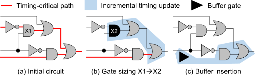
On the contrary, incrementality has been extensively studied in the classical design flow of digital circuits. For instance, design automation tools heavily count on incremental timing/power analysis algorithms for efficient circuit optimization [29, 14]. Figure 3 shows an example of timing-driven optimization. These algorithms explore incrementality along the circuit network and update quantities on a per-gate basis after optimization transforms (e.g., gate sizing, buffer insertion) change the design. However, such ideas are not easily applicable to incremental QCS because state values can be entangled and therefore are inseparable among gates. This property also brings another challenge to parallelization. For instance, although G7 and G8 in Figure 2 are structurally independent of each other, we cannot apply these two CNOT operations simultaneously as race can occur when both q4 and q3 are 1. We need a different task decomposition strategy to parallelize incremental QCS.
Extending existing QCS algorithms to incorporate incrementality is nontrivial, either. The biggest challenge is to maintain consistency or invariants in these algorithms when data structures of states and gates start to change. For instance, BDD can be extremely compact for full simulation [17], but its linear coupling between stages can incur expensive reorganization of a BDD when a local change happens in an early stage. Likewise, algorithms that count on restructuring input circuits [5] will need to manage an additional layer of consistency between the original and the modified circuits. Similar challenges exist in other full simulation algorithms as well [2, 4]. Although existing QCS algorithms and ideas in the classical design flow have their benefits, we believe a ground-up design of simulation system is necessary to overcome the unique challenges of incremental QCS.
III qTask: Task-parallel Incremental QCS
In this section, we introduce qTask, a new QCS engine that efficiently supports incrementality using task parallelism. qTask introduces a lightweight C++ programming model for incremental simulation and backs up the model with an efficient runtime that explores both inter- and intra-gate operation parallelisms from partitioned data blocks. We first discuss the targeted environment of qTask and then present its technical details. Throughout the discussion, we will use the circuit example in Figure 2 to explain key steps in qTask.
III-A Targeted Simulation Environment
qTask targets medium-size gate-level quantum circuits on a single machine that has sufficient memory to store all output amplitudes (). While qTask currently assumes all data fit in memory, the proposed partitioning strategy can be extended to a higher number of qubits using out-of-core memory, which is part of our future work. To comply with modern quantum computers, we target standard gates defined atomically in OpenQASM [30] and QASMBench [15], as shown in Table I. These standard gates can be 1) mapped to machine-specific gates for actual execution and 2) assembled to form composition gates (e.g., CZ, CCX, SWAP). Since qTask does not impose any constraints on gates, composition gates can be also included to our database using the same simulation method as standard gates.
| Gates | Functionality | Gates | Functionality |
|---|---|---|---|
| CNOT | Controlled-NOT | SDG | Conjugate of sqrt(Z) |
| X | Pauli-X gate | T | sqrt(S) phase |
| Y | Pauli-Y gate | TDG | Conjugate of sqrt(S) |
| Z | Pauli-Z gate | RX | X-axis rotation |
| H | Hadamard gate | RY | Y-axis rotation |
| S | sqrt(Z) phase | RZ | Z-axis rotation |
III-B Programming Model
Unlike existing quantum programming models that do not anticipate incrementality, qTask introduces a lightweight C++-based model with two new concepts: First, qTask groups application programming interface (API) to three categories, circuit modifier, state update, and query. The three categories describe operations that modify the circuit, update state amplitudes (incrementally), and query circuit quantities, respectively. Second, qTask asks users to explicitly structure gates on a per-net basis to facilitate the design of incremental QCS. A net is a group of gates that are parallel in structure (e.g., G1–G5 in Figure 2). Table II shows the key API to support incremental QCS in qTask. Currently, qTask does not support adding or removing a qubit as the number of qubits is typically decided in the beginning.
| Method | Functionality |
|---|---|
| insert_net | insert a new empty net to the circuit |
| remove_net | remove a net and all its gates from the circuit |
| insert_gate | insert a net gate to an existing net |
| remove_gate | remove a gate from its net and the circuit |
| update_state | update the state value, incrementally |
| dump_graph | dumps the current partition graph |
Listing 1 shows an example of qTask code for creating the quantum circuit in Figure 2. We start by creating a circuit object, ckt, with five qubits, q4, q3, q2, q1, and q0, where q4 is the most significant bit. Then, we create five nets using the method insert_net, which inserts a new net right after the net given in the argument. Since the five Hadamard gates are of no structural dependency, we insert them to net1. Next, we insert four CNOT gates to net2, net3, net4, and net5, respectively. If a gate is inserted to a net that introduces a dependency, such as G6 and G7, qTask will throw an exception. When we finish describing the circuit, calling dump_graph will dump the current task graph of partitioned blocks to a DOT format. Calling update_state will run the task graph to perform simulation. The last three lines modify the circuit by removing G8 and inserting a new CNOT gate G10, followed by calling update_state to re-simulate state amplitudes incrementally.
Internally, qTask does not maintain any gate dependency graph, such as the one in Figure 2, but a list of nets based on the order of their constructions. Since all the gates in a net are structurally parallel, qTask can group them in arbitrary order to design an efficient memory management scheme atop our task partitioning, discussed later.
III-C Task Decomposition Strategy
To facilitate the design of efficient incremental QCS, qTask employs a top-down parallel decomposition strategy using the task graph model. qTask divides a state vector into a set of disjoint, equal-size blocks and groups consecutive blocks to form partitions. Each partition spawns one or multiple tasks to perform gate operations on designated memory regions. This strategy breaks down gate dependencies to task dependencies among partitions, enabling inter-gate operation parallelism. If a partition contains more than one block, qTask further spawns parallel tasks to explore intra-gate operation parallelism among these blocks. By leveraging existing task graph programming systems, qTask transparently scales to many processors. Here, we focus on task partitioning first and will discuss how partitions are connected to each other as part of circuit modifiers and incremental update.
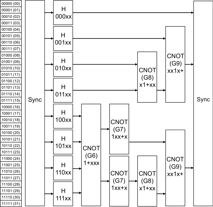
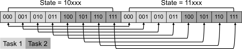
Figure 4 shows the partition diagram for the simulation workload of the quantum circuit in Figure 2. Each block size is a power of two (4 here) and represents the minimum number of elements or granularity for each task. The key idea behind our partitioning is to carry out gate operations over a state vector in two modes, non-superposition and superposition gates. Gate operations, such as CNOT, diagonal matrices, and permutations do not create superposition and can directly alter the state vector using linear swapping and scaling. For instance, the CNOT gate G6 in Figure 2 is equivalent to swapping state amplitudes between 10xxx and 11xxx, where “xxx” denotes all possible binary strings of the first three qubits (1+xxx for short). On the other hand, gate operations that result in superposition, such as non-diagonal matrices and rotators, will fall back to the use of state transformation matrix.
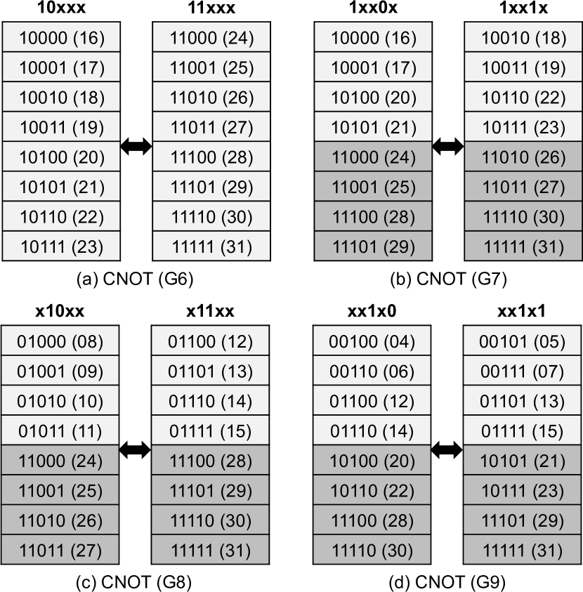
Figure 5 gives an example of how qTask performs CNOT using partitioned tasks. For G6, we need to swap eight amplitudes between 10xxx and 11xxx. Since the block size is 4, the eight swaps can be parallelized by two tasks, starting at states 10000 and 10100, respectively. However, the two tasks cannot appear in two parallel partitions because their memory regions overlap (i.e., and , using decimal representation). Instead, we form one partition of , as shown in Figure 4, and spawn the two parallel tasks within this partition to explore intra-gate operation parallelism, as illustrated in Figure 6. In qTask, intra-gate operation parallelism can be regarded as a parallel-for with chunk size equal to our block size. On the other hand, G7 results in two partitions that can run in parallel because the memory regions of the two blocks are and that do not overlap, as shown in Figure 4. The procedure to derive partitions for G8 and G9 is similar.
The memory region of a block can be quickly decided by replacing “x”s with the binary string of a multiple of . In Figure 5, for instance, the first and the second blocks of G6 are the two states by replacing xxx with 000 and 100, respectively. By iterating blocks in order, we can decide when to form a partition of consecutive blocks that overlap in memory regions. Furthermore, it can be observed that the proposed partitioning has a repetitive pattern (see Figure 4). Once we have found a partition, the rest can be quickly decided as they all have the same size by symmetry. qTask employs this algorithm to decide partitions for gates X, Y, Z, S, SDG, T, TDG, SWAP, and RX/RY/RZ of certain degrees that do not form superposition (e.g., RX()).
For gate operations that form superposition (e.g., Hadamard, RX()), qTask falls back to the principle of state transformation matrix. Since this process is equivalent to matrix-vector multiplication, we partition the state vector into an equal number of blocks and perform parallel multiplication. For instance, the first net of five Hadamard gates in Figure 2 will result in eight partitions each of one block, as shown in Figure 4. Each partition computes four amplitudes via multiplying the input state vector by the corresponding subset of matrix rows. Since the multiplication cannot start until the previous vector is ready, the eight partitions are preceded by a synchronization task, sync. Notice that each partition derives its subset of matrix rows on the fly to save memory and gain parallelism using recursive tensor products. We stop the recursion when zero and identity patterns occur.
III-D Circuit Modifiers
With a task graph in place, we can efficiently perform incremental QCS by restructuring the graph connectivity and identifying affected partitions to resimulate after a circuit modifier is applied. Since qTask partitions a state vector into contiguous blocks, connections between partitions can be quickly decided by a few forward and backward checks using range intersection algorithm. Specifically, a connection exists between two partitions if they are the closest pair of overlapped blocks. By scanning neighboring partitions and their block coverages, qTask can efficiently rebuild new connections and identify affected partitions for incremental update. We will focus on removing and inserting gates since net-level circuit modifiers can be built on top.
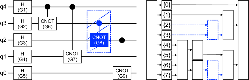
Figure 7 illustrates how removing a gate affects the graph connectivity. When we remove gate G8, all its partitions and relevant dependencies should be removed (marked in blue dash). For each removed partition, we need to reconnect its preceding partitions to its successor partitions if an overlap exist in their blocks. Since each partition is a group of consecutive blocks, by keeping a list of block indices covered by each partition, we can quickly decide overlapped partitions using range intersection algorithm. For instance, the first partition of G8 spans the block range , which intersects the block range of its successor.
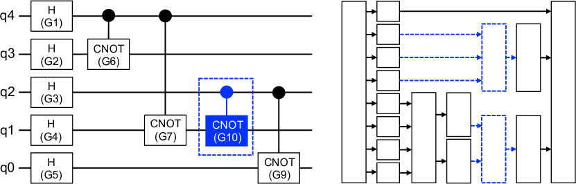
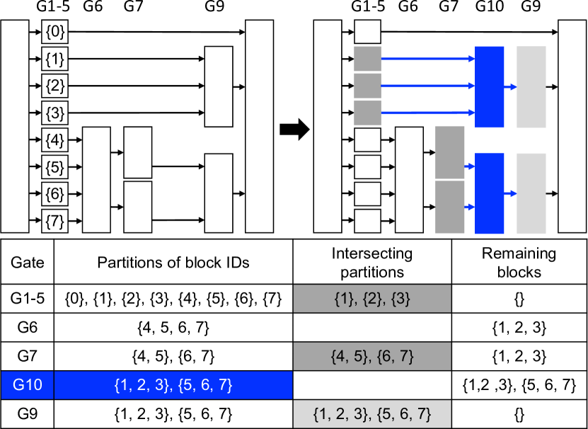
Figure 8 illustrates how inserting a new gate affects the graph connectivity. When a new gate G10 is inserted, we first identify its partitions (marked in blue dash) and then connect each partition with appropriate predecessors and successors. Figure 9 illustrates our algorithm to find such predecessors and successors. Starting from the row of G10, which has two partitions of block ranges and , we iteratively move backward and forward to find intersected partitions for predecessors and successors until the remaining blocks of G10 become empty. For example, with one step forward, the two partitions of G9 can all cover that of G10, resulting in two successor dependencies. Similarly, with one step backward, the two partitions of G7 cover only the second partition of G10, resulting in two predecessor dependencies; with two more steps backward, we have three predecessor dependencies that completely cover the first partition of G10. Since dependency constraints are transitive, we remove existing dependencies between these predecessors and successors.
III-E Incremental Update
qTask keeps a list of partitions called frontiers for each sequence of circuit modifiers. Frontiers are the source to start incremental update of affected state amplitudes when users issue an update call after a sequence of circuit modifiers. For each newly inserted gate, we add all its partitions to the frontier list. For each removed gate, we add all successors of removed partitions to the frontier list. Now, it should be clear that our partitioning strategy effectively scopes down state update to only successor partitions that are reachable from frontiers. Such successors can be found through a depth-first-search (DFS) starting from each frontier partition.
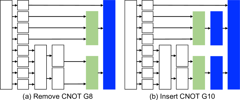
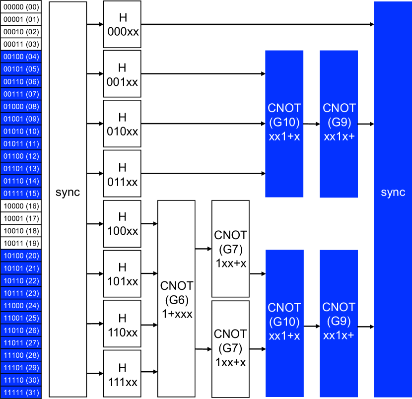
Figure 10 illustrates how qTask identifies frontiers and use them to carry out incremental update for Figure 7 and Figure 8. In (a), the two successor partitions of G8 (marked in green) are frontiers when G8 is removed from the circuit. Intuitively speaking, we only need to update state amplitudes of the two partitions and onward since removing G8 has no impact on other partitions. Similarly in (b), inserting G10 to the circuit introduces two new partitions to perform CNOT operations. The two partitions will be added to the frontier list and all their successors will participate in the incremental update. Figure 11 shows a detailed state map of Figure 10(b). We can see only 24 state amplitudes ( and ) are incrementally updated after removing G8 and inserting G10.
III-F Implementation Details
In this section, we discuss three important implementation details of qTask, task graph creation, per-net state vector management, and copy-on-write data optimization.
III-F1 Task graph creation
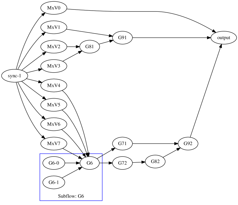
We leverage the Taskflow library [31] to derive a task graph from partitioned data blocks. We decide to use Taskflow because of its simplicity and many successful use cases in classical circuit design [32, 33, 34, 35, 36, 37, 38, 39, 40, 41, 42, 43], but other tasking libraries (e.g., TBB [44], OpenMP [45]) are also possible. Specifically, we use the static tasking and dynamic tasking (subflow) features [46] of Taskflow to compose inter- and intra-gate operation parallelisms, respectively. Figure 12 shows the Taskflow graph of Figure 4, where 1) 16 static tasks (sync-1, MxV0–MxV7, G71, G72, G81, G82, G91, G92, output) are used to formulate inter-gate operation parallelism and 2) one subflow of two static tasks (G6-0 and G6-1) is used to formulate intra-gate operation parallelism of G6. Each time the application requests a state update, qTask derives a new Taskflow graph from affected partitions and submits it to Taskflow’s work-stealing runtime [47] for parallel incremental simulation.
III-F2 Per-net state vector management
Since gates in the same net are structurally independent of each other, we first group superposition gates to share a state vector and partition it to an equal number of blocks, such as MxV0–MxV7 in Figure 12. These partitions will succeed an empty task (sync-1) that synchronizes all previous tasks to safely perform parallel matrix-vector multiplication. Next, we create a state vector for each non-superposition gate in the net and partition the vector into a set of consecutive blocks based on the proposed method. If multiple gates exist, we connect them in an increasing order of block count in partitions. This is because a partition of a high block count tends to affect a large number of downstream partitions, and we prefer to defer it as much as possible.
III-F3 Copy-on-write data optimization
While qTask keeps multiple state vectors per net to store intermediate results for incrementality, each state vector does not explicitly store all partitioned blocks. Instead, we leverage the copy-on-write (COW) technique [48] to optimize data access. Each block has a COW C++ smart pointer to its predecessor block. The memory and data of a block will not be created and copied until a task performs gate operations on the block. This COW optimization has two significant advantages: First, qTask will only create necessary data blocks for simulation. For example, the first and the fifth blocks of G9 in Figure 4 will not be created unless explicitly requested. Second, multiple memory allocations and data copies between blocks can be simultaneously performed through parallel tasks.
IV Experimental Results
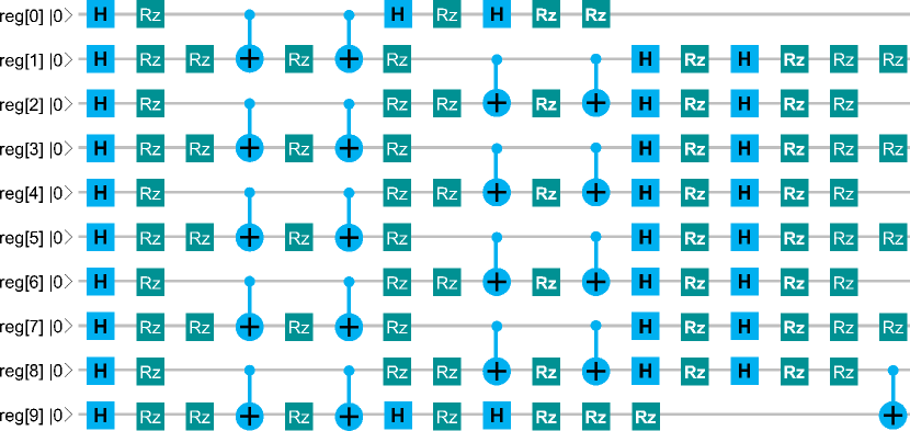
We evaluated the performance of qTask on 20 quantum circuits selected from medium- and large-scale QASMBench [15]. As shown in Table III, these circuits exhibit different complexities in terms of numbers of qubits and standard gates. For example, vqe_uccsd has the largest gate count of 10808, and big_ising has the largest qubit count of 26. All circuits except bb84 incorporate several CNOT gates to entangle and disentangle states. Figure 13 shows a fraction of the circuit, ising, that performs Ising model simulation using 10 qubits. All experiments ran on a CentOS 64-bit machine with 16 Intel i7 cores at 2.50 GHz and 128 GB RAM. We compiled qTask using clang++12 with C++17 standard -std=c++17 and optimization flag -O3 enabled. The default block size of qTask is 256. All data is an average of 10 runs.
| Circuit | Description | Qubits | Gates | CNOT | Qulacs | Qiskit | qTask | |||||||||||||||||||
|---|---|---|---|---|---|---|---|---|---|---|---|---|---|---|---|---|---|---|---|---|---|---|---|---|---|---|
|
|
|
|
|
|
|
|
|
||||||||||||||||||
| dnn | Quantum deep neural network | 8 | 1200 | 384 | 21.8 | 2167.8 | 0.07 | 51.4 | 5114.3 | 0.07 | 22.4 | 529.3 | 0.09 | |||||||||||||
| adder | Quantum ripple adder | 10 | 142 | 65 | 17.2 | 186.4 | 0.05 | 29.5 | 320.1 | 0.04 | 11.79 | 57.9 | 0.06 | |||||||||||||
| bb84 | Quantum key distribution | 8 | 27 | 0 | 1.1 | 2.3 | 0.03 | 1.1 | 2.4 | 0.03 | 1.5 | 1.9 | 0.04 | |||||||||||||
| bv | Berstein-Vazirani algorithm | 14 | 41 | 13 | 9.0 | 21.7 | 0.11 | 16.7 | 40.6 | 0.12 | 6.7 | 14.3 | 0.13 | |||||||||||||
| ising | Ising model simulation | 10 | 480 | 90 | 49.6 | 1438.1 | 0.08 | 81.4 | 2360.1 | 0.09 | 41.7 | 550.14 | 0.10 | |||||||||||||
| multiplier | Quantum multiplication | 15 | 574 | 246 | 150.9 | 4199.0 | 1.98 | 283.7 | 7896.3 | 2.86 | 101.62 | 1052.6 | 3.46 | |||||||||||||
| multiplier_35 | 35 matrix multiplication | 13 | 98 | 40 | 22.4 | 130.1 | 0.10 | 47.1 | 273.54 | 0.15 | 16.01 | 92.7 | 0.18 | |||||||||||||
| qaoa | Approximation optimization | 6 | 270 | 54 | 5.4 | 148.5 | 0.01 | 13.4 | 368.5 | 0.01 | 6.1 | 37.65 | 0.02 | |||||||||||||
| qf21 | Quantum factorization of 21 | 15 | 311 | 115 | 79.8 | 1173.1 | 1.59 | 191.5 | 2815.1 | 1.66 | 58.3 | 480.7 | 1.91 | |||||||||||||
| qft | Quantum Fourier transform | 15 | 540 | 210 | 142.0 | 3621.0 | 2.75 | 281.2 | 7170.1 | 3.11 | 102.2 | 949.4 | 3.17 | |||||||||||||
| qpe | Quantum phase estimation | 9 | 123 | 43 | 10.3 | 100.42 | 0.02 | 27.8 | 270.4 | 0.04 | 7.65 | 80.44 | 0.05 | |||||||||||||
| sat | Boolean satisfiability solver | 11 | 679 | 252 | 85.5 | 3660.7 | 0.11 | 196.7 | 8422.1 | 0.21 | 62.3 | 786.5 | 0.28 | |||||||||||||
| seca | Shor’s algorithm | 11 | 216 | 84 | 28.4 | 401.0 | 0.06 | 59.64 | 843.0 | 0.09 | 21.42 | 128.5 | 0.11 | |||||||||||||
| simons | Simon’s algorithm | 6 | 44 | 14 | 0.83 | 3.9 | 0.03 | 1.44 | 6.71 | 0.03 | 0.81 | 2.44 | 0.04 | |||||||||||||
| vqe_uccsd | Variational quantum eigensolver | 8 | 10808 | 5488 | 244.4 | 249084.2 | 0.36 | 435.1 | 443367.1 | 0.56 | 259.4 | 44251.1 | 0.76 | |||||||||||||
| big_adder | Quantum ripple adder | 18 | 284 | 130 | 200.1 | 2401.3 | 7.98 | 360.4 | 4300.8 | 11.4 | 137.9 | 602.5 | 13.9 | |||||||||||||
| big_bv | Bernstein-Vazirani algorithm | 19 | 56 | 18 | 125.0 | 305.9 | 2.6 | 234.5 | 573.9 | 3.9 | 95.4 | 126.6 | 4.9 | |||||||||||||
| big_cc | Counterfeit coin finding | 18 | 34 | 17 | 24.9 | 47.8 | 0.98 | 42.3 | 63.3 | 1.5 | 16.6 | 24.5 | 1.7 | |||||||||||||
| big_ising | Ising model simulation | 26 | 280 | 50 | 1939.1 | 3345.5 | 89.4 | 1745.3 | 2866.2 | 91.4 | 991.4 | 2000.3 | 114.3 | |||||||||||||
| big_qft | Quantum Fourier transform | 20 | 970 | 380 | 2936.3 | 100567.0 | 67.3 | 3012.6 | 144453.4 | 77.6 | 2209.7 | 12912.8 | 91.2 | |||||||||||||
| 1.46 | 5.77 | 0.74 | 1.71 | 9.76 | 0.82 | 1.00 | 1.00 | 1.00 | ||||||||||||||||||
-
1
Qubits: number of qubits Gates: number of standard gates CNOT: number of CNOT gates to entangle and disentangle states
-
2
full: runtime of full simulation inc: runtime of incremental simulation mem: maximum resident set size (RSS)
IV-A Baseline
Given the large number of quantum circuit simulators, it is impractical to compare qTask with all of them. Instead, we consider Qulacs [3] and Qiskit [16] as the baseline for the following three reasons: First, both Qulacs and Qiskit have an optimized C++ back-end and have demonstrated superior runtime performance over existing simulators [3]. Second, Qulacs is completely open-source and has relatively rich documentation for C++ in addition to Python, allowing us to reason the source when incrementality is taken into account. Third, Qulacs and Qiskit support circuit modification, in spite of no incremental simulation. For example, Qulacs have API for inserting/removing gates at given positions, while Qiskit allows adding/erasing gates as a byproduct of Python list.
IV-B Overall Simulation Performance
Table III presents the overall simulation performance of qTask, Qulacs, and Qiskit, using a maximum hardware concurrency of 16 threads. In terms of full simulation, which issues a simulation call when the entire circuit is constructed, qTask outperforms Qulacs and Qiskit in nearly all circuits. The average speed-ups of qTask over Qulacs and Qiskit across all circuits are and , respectively. We attribute this result to our partitioning strategy which explores both inter- and intra-gate operation parallelisms. This performance advantage becomes even more significant at larger circuits that produce more partitioned tasks and parallelism than small ones. For example, qTask simulates big_ising (26 qubits) 1.67 and 1.43 faster than Qulacs and Qiskit. For circuits of state sizes below our partition size (i.e., 8 qubits with 256 amplitudes), such as dnn, bb84, qaoa, and vqe_uccsd qTask is a bit slower than Qulacs because there is no much task parallelism. Yet, the difference is very negligible (e.g., about 5% in vqe_uccsd).
Next, we study the performance of incremental simulation. Following the convention of QASMBench, we create a net per level and insert all parallel gates at that level to the net. Starting from the first level, we repeat this process and issue level-by-level simulation calls until the entire circuit is constructed. That is, the number of simulation calls is equal to the number of nets or the circuit level/depth. With incremental simulation, we clearly see the advantage of qTask. On average, qTask is 5.77 and 9.76 faster than Qulacs and Qiskit, respectively. When a circuit include many gates in a long depth, this advantage becomes even more pronounced. Taking big_qft for example, qTask finished 7.79 and 11.19 faster than Qulacs and Qiskit, respectively. The trade-off of this large performance gain is higher memory usage, since we keep several state vectors per net to store intermediate results for incrementality. On average, qTask is 26% and 18% higher than Qulacs and Qiskit, both of which incorporate specialized sparse data structures for state vectors and matrices. However, how to efficiently extend such sparsity management to an incremental environment remains unknown.
IV-C Performance of Incremental Simulation
We further study the performance difference of incremental simulation between qTask and Qulacs over different numbers of circuit modifiers. Hereafter, we compare with only Qulacs since Qiskit is much slower. We follow the convention of classical design flow [14, 49, 50, 51] to define one incremental iteration as a sequence of circuit modifiers followed by a simulation call. We first demonstrate the simulation performance for incremental gate insertions. At each incremental iteration, we randomly select a few levels and insert all their gates into the circuit. Then, we call state update to re-simulate the modified circuit. Iterations stop until the circuit is fully constructed. Figure 14 draws the cumulative runtime over all incremental iterations for two circuits, qft and big_adder. As the number of incremental iterations increases, the performance gap between qTask and Qulacs becomes larger.
Next, we demonstrate the simulation performance for incremental gate removals. Starting from a complete circuit, each incremental iteration randomly selects a few levels and removes all their gates from the circuit. Then, we call state update to re-simulate the modified circuit. Iterations stop until the circuit becomes empty. Figure 15 draws the runtime at each incremental iteration for the same circuits, qft and big_adder. Notice that the runtime at the iteration 0 represents full simulation. As the number of incremental iterations increases, both Qulacs and qTask approach zero due to fewer gates to re-simulate, but qTask is always faster. qTask fluctuates more than Qulacs because the number of affected partitions varies across different incremental iterations. Removing gates at a later level will affect fewer downstream partitions that an earlier level, and vice versa.
Finally, we demonstrate the performance of incremental simulation performance by randomly mixing gate insertions and gate removals at each incremental iteration. Figure 16 plots the runtime over 50 incremental iterations. Since the circuit size varies at each iteration, both Qulacs and qTask fluctuate. However, we observe qTask is faster than Qulacs in nearly all points, as a result of incremental simulation. The runtime difference is larger at big_adder, which is primarily composed of non-superposition gates (CNOT, CX) to to perform quantum arithmetics. In this case, qTask can quickly update certain, affected amplitudes by circuit modifiers, rather than the entire state.
IV-D Multi-threading Performance
Figure 17 compares the runtime between Qulacs and qTask for completing full simulation using different numbers of cores. Both qTask and Qulacs saturate at about 10 cores. Since our task partitioning strategy enables both inter- and intra-gate operation parallelisms, multi-threaded qTask is always faster than Qulacs. Also, by modeling partitioned simulation tasks into a task graph, qTask can execute the whole-graph with dynamic load balancing (via Taskflow [31]) in no need of synchronizing work between levels as Qulacs. Similar result is observed for incremental simulation in Figure 18, where we collect 50 incremental iterations of random gate insertions and removals. For qTask, the advantage of multi-threading is less significant than full simulation because incremental simulation takes much less computation. The scalability saturates at about 10 cores because most task graphs give 10—-30 parallel tasks with a partition size of 256. Smaller partition size gives more task parallelism, but the resulting scheduling overhead can outweigh the advantage.
IV-E Impact of Block Size
We study the impact of different block sizes on simulation performance. In qTask, using a smaller block size results in more partitioned tasks and thus a finer control over incrementality, and vice versa. However, more partitions also incur higher runtime overhead, such as re-connecting the task graph after circuit modifiers and scheduling tasks with dynamic load balancing. Figure 19 shows the simulation runtime of qTask for qft (15 qubits) using different block sizes. When the block size is too small, the overhead of task partitioning and scheduling completely outweighs the advantage of task parallelism. When the block size is to too large, qTask does not benefit much from task parallelism, and the result basically degenerates to using one core (compared to Figure 17 and Figure 18).
The selection of partition size depends on the circuit structure and application environment. For example, if the simulator only has four cores to run, then a bigger partition size is better for avoiding excessive parallelism plus scheduling overhead. On the other hand, if the circuit incorporates a long chain of arithmetic operations (e.g., CNOT), a smaller partition size may bring more inter-gate parallelism. Since there is no universal optimal selection, we have decided to parameterize it for users.
IV-F Impact of Copy-on-Write Data Optimization
qTask partitions each state vector into a set of data blocks and stores each partitioned block using a C++ COW smart pointer [48]. A data block is automatically freed when reference count drops to zero, which happens on the fly by Taskflow’s scheduler. In general, this data block management strategy can reduce the overall memory footprint by about 20–50%. For large-scale circuits, e.g., big_qft and big_ising, the saving can be significant (up to several GBs).
V Conclusion
In this paper, we have introduced qTask to efficiently support incremental quantum circuit simulation. To the best knowledge of authors, qTask is the first incremental quantum circuit simulator in the literature. We have presented a task-parallel decomposition strategy to explore both inter- and intra-gate operation parallelisms from partitioned data blocks. Our strategy effectively scopes down incremental update to a small set of affected partitions that can be quickly identified from a sequence of circuit modifiers. We have demonstrated the promising performance of qTask on medium- and large-scale quantum circuits from QASMBench. Compared to two state-of-the-art simulators, Qulacs and Qiskit, qTask is respectively 1.46 and 1.71 faster for full simulation and 5.77 and 9.76 faster for incremental simulation.
As part of our future work, we are enhancing qTask to support a higher number of qubits by extending its state vector data structure to out-of-core memory and distributed computing [52, 53]. Additionally, we plan to leverage the new CUDA Graph execution model [54, 55, 56] to accelerate large simulation task graphs using GPU computing. Integrating qTask into existing quantum circuit synthesis engines [7, 57] is also of our interest.
Acknowledgment
We are grateful for the support of National Science Foundation (NSF) grants, CCF-2126672, CCF-2144523 (CAREER), OAC-2209957, and TI-2229304. Also, the authors would like to thank reviewers for their constructive comments on improving this paper.
References
- [1] M. A. Nielsen and I. L. Chuang, Quantum Computation and Quantum Information: 10th Anniversary Edition. Cambridge University Press, 2011.
- [2] X.-C. Wu, S. Di, E. M. Dasgupta, F. Cappello, H. Finkel, Y. Alexeev, and F. T. Chong, “Full-State Quantum Circuit Simulation by Using Data Compression,” in SC, 2019.
- [3] Y. Suzuki, Y. Kawase, Y. Masumura, Y. Hiraga, M. Nakadai, J. Chen, K. M. Nakanishi, K. Mitarai, R. Imai, S. Tamiya, T. Yamamoto, T. Yan, T. Kawakubo, Y. O. Nakagawa, Y. Ibe, Y. Zhang, H. Yamashita, H. Yoshimura, A. Hayashi, and K. Fujii, “Qulacs: a fast and versatile quantum circuit simulator for research purpose,” Quantum, vol. 5, p. 559, oct 2021.
- [4] A. Fatima and I. L. Markov, “Faster Schrödinger-style simulation of quantum circuits,” in IEEE HPCA, 2021, pp. 194–207.
- [5] R. Iten, R. Moyard, T. Metger, D. Sutter, and S. Woerner, “Exact and Practical Pattern Matching for Quantum Circuit Optimization,” ACM TQC, vol. 3, no. 1, Jan 2022.
- [6] G. G. Guerreschi, “Fast simulation of quantum algorithms using circuit optimization,” Quantum, vol. 6, p. 706, May 2022.
- [7] A. Zulehner and R. Wille, “Introducing Design Automation for Quantum Computing,” in Springer, 2020.
- [8] “Classiq: Quantum Algorithm Design,” https://www.classiq.io/docs/quantum-algorithm-design.
- [9] P. Gokhale, Y. Ding, T. Propson, C. Winkler, N. Leung, Y. Shi, D. I. Schuster, H. Hoffmann, and F. T. Chong, “Partial Compilation of Variational Algorithms for Noisy Intermediate-Scale Quantum Machines,” in IEEE/ACM Micro, 2019, p. 266–278.
- [10] G. S. Ravi, P. Gokhale, Y. Ding, W. Kirby, K. Smith, J. M. Baker, P. J. Love, H. Hoffmann, K. R. Brown, and F. T. Chong, “CAFQA: A Classical Simulation Bootstrap for Variational Quantum Algorithms,” in ACM ASPLOS, 2022, p. 15–29.
- [11] T. Peham, L. Burgholzer, and R. Wille, “Equivalence checking paradigms in quantum circuit design: A case study,” in ACM/IEEE DAC, 2022, p. 517–522.
- [12] O. Daei, K. Navi, and M. Zomorodi-Moghadam, “Optimized Quantum Circuit Partitioning,” International Journal of Theoretical Physics volume, pp. 3804––3820, 2020.
- [13] T.-W. Huang and M. Wong, “UI-Timer 1.0: An Ultrafast Path-Based Timing Analysis Algorithm for CPPR,” IEEE TCAD, vol. 35, no. 11, pp. 1862–1875, 2016.
- [14] T.-W. Huang, G. Guo, C.-X. Lin, and M. Wong, “OpenTimer 2.0: A New Parallel Incremental Timing Analysis Engine,” IEEE TCAD, vol. 40, no. 4, pp. 776–789, 2021.
- [15] A. Li, S. Stein, S. Krishnamoorthy, and J. Ang, “QASMBench: A Low-Level Quantum Benchmark Suite for NISQ Evaluation and Simulation,” ACM TQC, Jul 2022.
- [16] “Qiskit,” https://qiskit.org/.
- [17] L. Burgholzer, A. Ploier, and R. Wille, “Exploiting Arbitrary Paths for the Simulation of Quantum Circuits with Decision Diagrams,” in IEEE DATE, 2022, pp. 64–67.
- [18] Y. Zhao, Y. Guo, Y. Yao, A. Dumi, D. M. Mulvey, S. Upadhyay, Y. Zhang, K. D. Jordan, J. Yang, and X. Tang, “Q-GPU: A Recipe of Optimizations for Quantum Circuit Simulation Using GPUs,” in IEEE HPCA, 2022, pp. 726–740.
- [19] “cuQuantum,” https://github.com/NVIDIA/cuQuantum.
- [20] S. Imamura, M. Yamazaki, T. Honda, A. Kasagi, A. Tabuchi, H. Nakao, N. Fukumoto, and K. Nakashima, “mpiQulacs: A Distributed Quantum Computer Simulator for A64FX-based Cluster Systems,” 2022.
- [21] G. G. Guerreschi, J. Hogaboam, F. Baruffa, and N. P. D. Sawaya, “Intel quantum simulator: a cloud-ready high-performance simulator of quantum circuits,” Quantum Science and Technology, vol. 5, no. 3, may 2020.
- [22] “Microsoft Q# and the Quantum Development Kit.”
- [23] “Google QSim,” https://quantumai.google/qsim.
- [24] T. Vincent, L. J. O’Riordan, M. Andrenkov, J. Brown, N. Killoran, H. Qi, and I. Dhand, “Jet: Fast quantum circuit simulations with parallel task-based tensor-network contraction,” Quantum, vol. 6, p. 709, May 2022.
- [25] A. Deshpande, A. Mehta, T. Vincent, N. Quesada, M. Hinsche, M. Ioannou, L. Madsen, J. Lavoie, H. Qi, J. Eisert, D. Hangleiter, B. Fefferman, and I. Dhand, “Quantum computational advantage via high-dimensional Gaussian boson sampling,” Science Advances, vol. 8, no. 1, 2022.
- [26] C. Ibrahim, D. Lykov, Z. He, Y. Alexeev, and I. Safro, “Constructing Optimal Contraction Trees for Tensor Network Quantum Circuit Simulation,” 2022.
- [27] S. Bravyi and D. Gosset, “Improved Classical Simulation of Quantum Circuits Dominated by Clifford Gates,” Phys. Rev. Lett., vol. 116, p. 250501, Jun 2016.
- [28] A. Zulehner, P. Niemann, R. Drechsler, and R. Wille, “Accuracy and Compactness in Decision Diagrams for Quantum Computation,” in IEEE DATE, 2019, pp. 280–283.
- [29] T.-W. Huang, P.-C. Wu, and M. D. F. Wong, “UI-Timer: An Ultra-Fast Clock Network Pessimism Removal Algorithm,” in IEEE/ACM ICCAD, 2014, p. 758–765.
- [30] A. Cross, A. Javadi-Abhari, T. Alexander, N. D. Beaudrap, L. S. Bishop, S. Heidel, C. A. Ryan, P. Sivarajah, J. Smolin, J. M. Gambetta, and B. R. Johnson, “OpenQASM 3: A broader and deeper quantum assembly language,” ACM TQC, vol. 3, no. 3, pp. 1–50, Sep 2022.
- [31] T.-W. Huang, D.-L. Lin, C.-X. Lin, and Y. Lin, “Taskflow: A Lightweight Parallel and Heterogeneous Task Graph Computing System,” IEEE TPDS, vol. 33, no. 6, pp. 1303–1320, 2021.
- [32] T.-W. Huang, C.-X. Lin, G. Guo, and M. Wong, “Cpp-Taskflow: Fast Task-based Parallel Programming using Modern C++,” in IEEE IPDPS, 2019, pp. 974–983.
- [33] C.-X. Lin, T.-W. Huang, G. Guo, and M. D. F. Wong, “A modern c++ parallel task programming library,” in ACM Multimedia Conference, 2019, p. 2284–2287.
- [34] T.-W. Huang, “A General-purpose Parallel and Heterogeneous Task Programming System for VLSI CAD,” in IEEE/ACM ICCAD, 2020.
- [35] T.-W. Huang, D.-L. Lin, Y. Lin, and C.-X. Lin, “Taskflow: A General-purpose Parallel and Heterogeneous Task Programming System,” IEEE TCAD, vol. 41, no. 5, pp. 1448–1452, 2022.
- [36] T.-W. Huang, Y. Lin, C.-X. Lin, G. Guo, and M. D. F. Wong, “Cpp-taskflow: A general-purpose parallel task programming system at scale,” IEEE TCAD, vol. 40, no. 8, pp. 1687–1700, 2021.
- [37] D.-L. Lin, H. Ren, Y. Zhang, B. Khailany, and T.-W. Huang, “From RTL to CUDA: A GPU Acceleration Flow for RTL Simulation with Batch Stimulus,” in ACM ICPP, 2023.
- [38] D.-L. Lin, Y. Zhang, H. Ren, S.-H. Wang, B. Khailany, and T.-W. Huang, “GenFuzz: GPU-accelerated Hardware Fuzzing using Genetic Algorithm with Multiple Inputs,” in ACM/IEEE DAC, 2023.
- [39] Z. Guo, T.-W. Huang, and Y. Lin, “Heterocppr: Accelerating common path pessimism removal with heterogeneous cpu-gpu parallelism,” in IEEE/ACM ICCAD, 2021, pp. 1–9.
- [40] C.-H. Chiu and T.-W. Huang, “Composing Pipeline Parallelism Using Control Taskflow Graph,” in ACM HPDC, 2022, p. 283–284.
- [41] K. Zhou, Z. Guo, T.-W. Huang, and Y. Lin, “Efficient Critical Paths Search Algorithm using Mergeable Heap,” in IEEE/ACM ASP-DAC, 2022, pp. 190–195.
- [42] C.-H. Chiu and T.-W. Huang, “Efficient Timing Propagation with Simultaneous Structural and Pipeline Parallelisms: Late Breaking Results,” in ACM/IEEE DAC, 2022, p. 1388–1389.
- [43] G. Guo, T.-W. Huang, and M. D. F. Wong, “Fast STA Graph Partitioning Framework for Multi-GPU Acceleration,” in IEEE/ACM DATE, 2023.
- [44] M. Voss, R. Asenjo, and J. Reinders, Pro TBB: C++ Parallel Programming with Threading Building Blocks. Apress, 2019.
- [45] “OpenMP,” https://www.openmp.org/.
- [46] C.-X. Lin, T.-W. Huang, G. Guo, and M. Wong, “An Efficient and Composable Parallel Task Programming Library,” in IEEE HPEC, 2019, pp. 1–7.
- [47] C.-X. Lin, T.-W. Huang, and M. D. F. Wong, “An efficient work-stealing scheduler for task dependency graph,” in 2020 IEEE ICPADS, 2020, pp. 64–71.
- [48] “Copy-on-Write,” https://en.wikipedia.org/wiki/Copy-on-write.
- [49] T.-W. Huang and M. Wong, “OpenTimer: A high-performance timing analysis tool,” in IEEE/ACM ICCAD, 2015, pp. 895–902.
- [50] Z. Guo, T.-W. Huang, and Y. Lin, “GPU-accelerated Static Timing Analysis,” in IEEE/ACM ICCAD, 2020, pp. 1–8.
- [51] G. Guo, T.-W. Huang, Y. Lin, and M. Wong, “GPU-accelerated Pash-based Timing Analysis,” in ACM/IEEE Design Automation Conference (DAC), 2021.
- [52] T.-W. Huang, C.-X. Lin, and M. D. F. Wong, “DtCraft: A distributed execution engine for compute-intensive applications,” in IEEE/ACM ICCAD, 2017, pp. 757–765.
- [53] ——, “DtCraft: A High-Performance Distributed Execution Engine at Scale,” IEEE TCAD, vol. 38, no. 6, pp. 1070–1083, 2019.
- [54] D.-L. Lin and T.-W. Huang, “A Novel Inference Algorithm for Large Sparse Neural Network using Task Graph Parallelism,” in IEEE HPEC, 2020, pp. 1–7.
- [55] ——, “Efficient GPU Computation using Task Graph Parallelism,” in EuroPar, 2021.
- [56] ——, “Accelerating Large Sparse Neural Network Inference using GPU Task Graph Parallelism,” IEEE TPDS, vol. 33, no. 11, pp. 3041–3052, 2022.
- [57] G. Nannicini, L. S. Bishop, O. Günlük, and P. Jurcevic, “Optimal Qubit Assignment and Routing via Integer Programming,” ACM Transactions on Quantum Computing, vol. 4, no. 1, oct 2022.