Semi-autonomous Prosthesis Control Using Minimal Depth Information and Vibrotactile Feedback
Abstract
A semi-autonomous prosthesis control based on computer vision can be used to improve performance while decreasing the cognitive burden, especially when using advanced systems with multiple functions. However, a drawback of this approach is that it relies on the complex processing of a significant amount of data (e.g., a point cloud provided by a depth sensor), which can be a challenge when deploying such a system onto an embedded prosthesis controller. In the present study, therefore, we propose a novel method to reconstruct the shape of the target object using minimal data. Specifically, four concurrent laser scanner lines provide partial contours of the object cross-section. Simple geometry is then used to reconstruct the dimensions and orientation of spherical, cylindrical and cuboid objects. The prototype system was implemented using depth sensor to simulate the scan lines and vibrotactile feedback to aid the user during aiming of the laser towards the target object. The prototype was tested on ten able-bodied volunteers who used the semi-autonomous prosthesis to grasp a set of ten objects of different shape, size and orientation. The novel prototype was compared against the benchmark system, which used the full depth data. The results showed that novel system could be used to successfully handle all the objects, and that the performance improved with training, although it was still somewhat worse compared to the benchmark. The present study is therefore an important step towards building a compact system for embedded depth sensing specialized for prosthesis grasping.
Index Terms:
semi-autonomous control, myoelectric prosthesis, depth sensing, laser scanner, minimal data, vibrotactile feedback, point cloud processing.I Introduction
Despite the development of technology, modern prosthesis are still often rejected by their users [1]. One factor that contributes to the rejection is the difficulty in controlling the device. The commercial systems are controlled by recording myoelectric signals to estimate the user motion intention, which is then translated into prosthesis commands. This approach establishes a direct and intuitive connection between the user’s brain and the prosthesis, but the subject is responsible for explicit control of all system functions, and this can be slow and cognitively taxing especially in the case of complex systems. The myoelectric control methods are constantly developing and some methods, such as pattern classification, hold promise to make the control more efficient and less cognitively taxing [2, 3]. Another approach that can be used to address this challenge is the semi-autonomous control, which has been proposed long ago [4] and developed by several research groups [5, 6, 7, 8, 9, 10, 11, 12, 13]. Such control is often implemented by placing a vision sensor on a prosthesis, so that the artificial controller can “see” the object that the user would like to grasp. By inferring object properties such as shape, size and orientation from the imaging data, the controller can define an adequate prosthesis configuration that is suitable for grasping the object. Thus, the prosthesis behaviour can be automated and the system can simultaneously activate multiple prosthesis degrees-of-freedom (DOF) [10], which would be difficult using conventional approaches. Hence, as the prosthesis controller performs some functions automatically, the semi-autonomous control can alleviate the cognitive burden and tests have shown that it can outperform classification-based approaches [14].
Different types of vision sensors have been used to implement semi-autonomous control: regular webcams [4, 6, 7, 8, 13]; stereo-camera pairs [5]; depth sensors [10, 15]; or even AR headsets [14], and the sensors were placed on-head (egocentric) [5, 15, 7, 14] and on-prosthesis, either on-hand [4, 10] or on-forearm [8, 13]. In addition, recent studies presented solutions in which small RGB cameras were integrated into the hand [11, 12] or fingers [16]. Placing the sensor on the hand enables a self-contained system but it also requires an aiming step, where the user aligns the prosthesis towards the target object so that the is in the sensor’s field-of-view [10].
However, one of the disadvantages of the semi-autonomous approach is that it relies on complex processing of an abundance of data. For instance, RGB-based controllers perform image processing using traditional blob analysis [4], edge detection algorithms [7], or deep neural networks [6, 9, 8, 13], and some of these works even rely on understanding the temporal/dynamic nature of grasping by analysing multiple frames of a grasping sequence [8, 13]. In addition, most of these approaches are based on some form of classification, which requires extensive amounts of training data and still decodes a finite set of prosthesis configurations encompassed by the training set. This limitation can be avoided using depth sensors, where the controller can harvest the power of computational geometry to estimate the position and orientation of the target object from the reconstructed 3-D point cloud data. Commonly, this is accomplished by fitting generic geometric models (e.g. sphere, cylinder or cuboid model) to the data after processing, either by surface/planar data removal [5, 15] or by segmentation [14, 10]. Depth data analysis is, however, computationally even more demanding than RGB data processing.
The aforementioned computational complexity is a critical challenge as, for successful clinical translation, the processing pipeline needs to be implemented within the embedded system of a prosthesis with limited software and hardware resources. One way to reduce the computational complexity would be to use less data and simpler processing, ideally without compromising the performance. While stereo-vision or depth sensors can retrieve the 3-D structure of a whole scene (i.e. environment), most of that data is not relevant for prosthesis grasping; the critical information is the structure of the target object. In that sense, 2-D laser scanners can retrieve minimalist but still relevant depth data. This time-of-flight technology has been widely used in different robotics areas such as robot localization and mapping [17], automated inspection [18], vehicle counting [19] or forestry [20]. The lasers have been already applied to dexterous robotic hands to enhance grasping. The DLR hand [21] included embedded light projection laser diodes at the tip of each finger to support reconstruction using a passive stereo-camera pair. Many years later, Quigley et al. [22] similarly used a laser line scanner on the back of the one of the robotic fingertips of their dexterous hand, also for object reconstruction through multiple finger sweeping. Still, this technology has not yet been applied to control grasping of a semi-autonomous prosthesis.
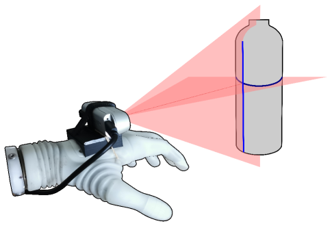
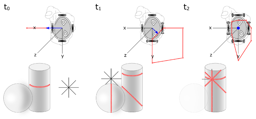
The present manuscript, therefore, investigates if a set of simulated laser scanners can be used to fully reconstruct the shape, size and orientation of a target object. The idea is to perform multiple laser ”cuts” as they provide partial contours of an object’s cross-sections, as shown in Fig. 1, and reconstruct the object properties from such contours using simple geometry.
To test this concept functionally, a semi-autonomous prosthesis controller was implemented and assessed on able-bodied volunteers who used the prosthesis to perform a functional task. Since the present work is exploratory, the laser scanners were simulated by using a depth sensor placed on the hand. As explained before, this placement requires the user to aim the prosthesis towards the object, which is not trivial and can take time [10]. Hence, to facilitate the aiming, we have equipped the prosthesis with a vibrotactile system that provides online aiming cues to properly orient the prosthesis. Finally, the novel method was tested against the recently developed benchmark [10] to evaluate the performance of the system using minimum data versus the benchmark that uses the full data. The hypothesis was that, after some training, the minimal system plus vibrotactile feedback would perform on par with the benchmark.
II Methods
II-A Using Laser Scanners to Retrieve Object Shape And Size
II-A1 Number of 2-D Laser Lines
The aim of the minimalist depth system is to use laser scanners to estimate object shape, size and orientation to enable prosthesis grasping. More specifically, the method should ensure an accurate reconstruction of any object that can be approximated by a spherical, cylindrical or cuboid model, as those three shapes encompasses the majority of daily life objects. When scanned by a laser, these models produce particular types of contours based on their cross-section: a) a partial circle contour is obtained from a spherical object; b) a straight line contour is obtained from a cuboid object; and c) both of these can arise from a cylindrical object (as illustrated in Fig. 1), which can additionally show a partial ellipse contour if an oblique laser cut is made.
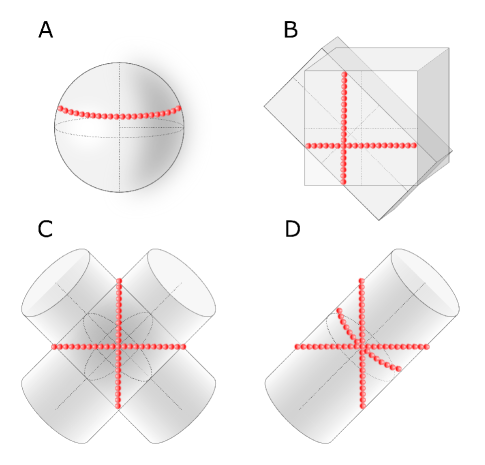
The simplest system that can be conceptualized contains a single laser line. The scanner could be placed in two possible configurations, so that the laser line is parallel or perpendicular to the dorsal plane of the prosthetic hand. Importantly, even such a simple system would be able to estimate the shape and size of objects placed vertically or horizontally. For instance, the horizontal scan line for an upright cylindrical object would be a circle with the diameter corresponding to the object size, and this information could be used to rotate the wrist and open the hand automatically. However, this design has some critical limitations. The user would have to manually orient the prosthesis using compensatory movements for every object that is not ”properly” aligned with the sensor. For example, if the scan line is parallel to the dorsal plane of the hand and the cylindrical object lays on the table, the user would need to manipulate the prosthesis so that the scanner “cuts” the object vertically (across its long axis). Furthermore, in case the targeted object is spherical, its true diameter can only be estimated by aiming directly at its equatorial line (Fig. 2-A).
The next configuration would be a system incorporating two laser lines, one parallel to the dorsal plane of the prosthetic hand and another perpendicular to it. Compared to a single scan line, such system can i) fully resolve a spherical object, and ii) discern between horizontally and vertically placed cylindrical and cuboid objects. However, the real dimensions and orientation of such objects cannot be inferred if the objects are tilted (Fig. 2-B and 2-C).
Therefore, this study proposes a system built with a hypothetical laser scanner capable of emitting four concurrent laser lines separated by 45°. As it will be explained in the following section, this configuration can fully resolve object dimensions and orientation using simple geometry for all models of interest. This is the minimal number of laser scans to reconstruct idealized 3-D geometric primitives. For instance, this cannot be accomplished using only three laser lines since the longitudinal direction of a cylinder could not always be correctly estimated (e.g., Fig. 2-D).
II-A2 Geometric reconstruction of 3-D models
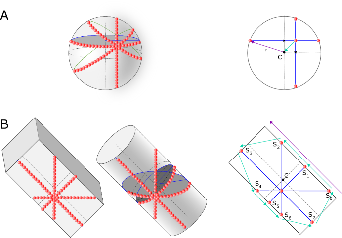
Figure 3 illustrates how the shape, dimension and orientation of a spherical, a cylindrical or a cuboid object can be retrieved using four scan lines. The line in which all laser scans intersect is hereafter named optical z-axis. Spherical objects (Fig. 3-A) are a special case since only two laser scans are required. Each scan results in a partial circular contour, and therefore a circle model can be fitted to the contour data using Random Sample Consensus (RANSAC) [23]. The centers of the fitted circle models lie in the plane that is perpendicular to the optical z-axis and contains the center of the sphere. Therefore, the z-coordinate of that plane, and hence the z-coordinate of the sphere center, can be estimated by computing the average of the z-coordinates of the two circles. Next, the x- and y-coordinates of the sphere center (point in Fig. 3-A, right) are directly given by the x and y coordinates of the two circle centers, respectively. The radius of the sphere can finally be computed as the vector distance between the center point of the sphere and one of the extreme points.
The reconstruction of a cuboid or a cylindrical object is more complex but is also based on fitting of 2-D geometric models using all four laser scans simultaneously (see Fig. 3-B). A cuboid object requires fitting four line models, whereas a cylinder can be described either by four ellipses or by two ellipses, a circle and a line, depending on the position and orientation of the optical z-axis (i.e., user aiming at the object). The first step is to find the plane that corresponds to the face of a cuboid object ”pierced” by the optical z-axis, or in the case of a cylinder, the longitudinal plane that divides the cylinder in two semi-cylinders. To accomplish that, the extreme inlier points of each laser scan are found. The face plane of the cuboid is then determined by computing the cross product between two vectors built from three non-collinear extreme points. The longitudinal plane of the cylinder is determined similarly but with the constraint that extreme points need to belong to a circle or an ellipse. The center of the cylinder can then be estimated by averaging the coordinates of the centers of the circle and/or of the ellipses. Once the planes are determined, the orientation and dimensions of the 3-D objects are obtained by an algorithm illustrated in Fig. 3-B, right.
First, all extreme points are projected onto the respective plane. The projected points are designated as seed points and are sorted counter-clockwise ( to as in Fig. 3-B, right). If the measured angle between the inbound and outbound vectors at a given seed point is less than (i.e. the vectors are nearly parallel), then the vector is one of the principal directions of the shape. The pseudo-code of the Algorithm 1 is given below.
To identify the shape of the target object (spherical, cuboid and cylindrical), three 2-D primitive models (circle, line and ellipse) are concurrently fitted to the data provided by each laser scan. The count of the best fitted models is used to define the reconstructed object shape: i) all circles, a sphere; ii) all lines, a cuboid; iii) all ellipses or one circle, one line and two ellipses, a cylinder. The pipeline was implemented in C++ using the open-source Point Cloud Library (PCL) v1.11.1 [24]. Since the PCL does not provide an ellipse model for RANSAC fitting, custom code was implemented (see Appendix V).
II-B Semi-autonomous Prosthesis Prototype
II-B1 Equipment
The Michelangelo prosthetic hand (Ottobock, Duderstadt, Germany) was used to test the proposed semi-autonomous control. The prosthesis integrates two Degrees-of-Freedom (DoF), namely wrist rotation and grasping, and it can perform two different grip types: palmar and lateral, however, only palmar grasp was considered in this study. Two active/dry electrodes (Model 13E200=50, Ottobock, Duderstadt, Germany) were used to record a pre-amplified and rectified double-differential surface electromyographic (sEMG) signal. The electrodes were placed on the right forearm of the participants, above the wrist flexor and extensor muscles, while the prosthesis was worn on their left forearm using a custom-made splint.
The prosthesis was connected to a laptop (Intel® Core™ i7-8665U CPU @1.90GHz, 2.1GHz, 4 Cores, 8 Logical Processors, with 32 GB RAM) through a Bluetooth link. The prosthesis sensor data and sEMG signals were sampled by the internal prosthesis controller at a frame rate of 100 Hz and sent to the laptop, which computed velocity control commands and transmitted them back to the prosthesis.
An active infrared stereo camera (Realsense™ D435i, Intel, US) was placed dorsally on the hand. The respective depth data stream, with a resolution of 424x240 px at 90 fps, was sent to the laptop using a two meter active USB-A 3.0 extension cable (DELTACO Prime, SweDeltaco AB, Stockholm, Sweden).
Vibrotactile sensory feedback was also provided to the participants on the same forearm carrying the prosthesis to assist aiming towards target objects, when using the laser scan prototype. This equipment (C2 tactors, Engineering Acoustics Inc, Casselberry, FL USA) was connected directly to the laptop via a USB cable and functioned as described in Section II-B3.
II-B2 System Operation
The laser scanner emitting four concurrent laser lines was simulated using the point cloud data obtained from the Realsense™ camera. First, the raw data was truncated to a bounding box of 100x100x100 mm located 150 mm in the front of the sensor. Afterwards, the four scan lines separated by 45°were extracted from the point cloud data. A tolerance of 1 mm was chosen to define that a given data point belonged to a specific laser scan, otherwise the point was discarded.
The implementation of this prototype followed a top-down approach, similar to that presented in Castro & Dosen [10]: the three 3-D primitive shapes are inferred in parallel using multi-threading as explained in Section II-A2. For each primitive, four RANSACs (one per laser line) are performed consecutively. Given that a circle is a particular case of an ellipse with equal semi-axes length, a rule was imposed such that a cylindrical primitive was chosen only when the fitting percentage was more than twice of that of the spherical primitive. Lastly, even though no 2-D circle primitives were used for fitting in the reconstruction of the cylindrical 3-D primitive, such primitive implies two RANSAC fittings (of an ellipse and of a straight line) per laser line, yielding a total of eight RANSAC fittings for reconstructing a cylindrical primitive. Therefore, the most costly performance time-wise comes from the system trying to fit a cylindrical model to any given object.
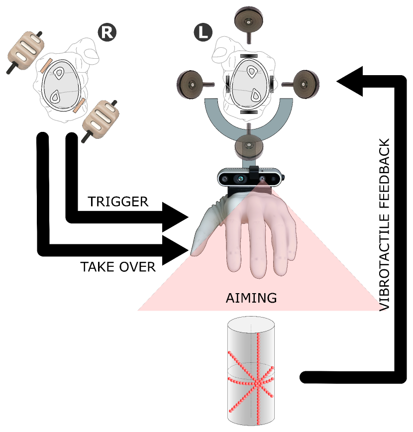
The vision-based semi-autonomous control used in this study is a combination of automatic and direct/manual control (Fig. 4). The prosthesis started in idle state, in which it constantly processed depth data detected within a predefined capturing volume, as explained above, while awaiting for the participant to generate a command to trigger the automatic control. The participant was responsible for aiming at the object he/she desired to grasp. To facilitate aiming, vibrotactile feedback was delivered to the forearm where the prosthesis was worn. Four vibrotactors provided the tactile cues guiding the user to direct the optical z-axis to fall within the target object (full details provided in Section II-B3).
Once the participant correctly aimed within the target object and the object was successfully reconstructed, all vibrotactors pulsed simultaneously. That signaled to the participant that the prosthesis was ready and waiting for a command to pre-shape. The participant could then send an ”auto-preshape” command to the prosthesis by performing a quick wrist flexion. In response, the prosthesis adjusted its wrist orientation and grasp size according to the estimated object model. Importantly, if he/she was not satisfied with the automatically selected hand configuration, he/she could aim again at the same or at different object.
If the selected hand configuration was appropriate, the participant could proceed to hand closing. To this aim, he/she could take over the control by performing a quick wrist extension movement. The prosthesis then moved proportionally to the recorded EMG (direct control), and switched back to the idle mode as soon as the object was transported and released.
II-B3 Vibrotactile Feedback for Aiming Guidance
Figure 5 shows the placement of the four tactors around the forearm. The tactors started vibrating as soon as the system detected an object, and the active tactor(s) indicated the direction in which the user should move the prosthesis, while the vibration intensity conveyed the distance of the optical z-axis from the object. Object detection and computation of the vibrotactile cues were accomplished using the raw depth data obtained from the laser scans, before the fitting of the geometric primitives, as explained below.
When one or more depth points were detected within the capture volume, the aiming guidance procedure was triggered. To simplify the problem, all points were projected onto the xOy-plane by setting their z-coordinate to zero. The respective 2-D convex hull was then recursively computed using the QuickHull algorithm [25]. The norm and orientation of the shortest-distance vector to the hull was then used for cueing the user towards the object(s). The vector was normalized to the maximum width of the capturing volume and converted to polar coordinates. The vibration signal was then conveyed to the user as a continuous signal with the amplitude inversely proportional to the distance to the object: i.e. the amplitude increased as the user approached the object (Fig. 5-A and 5-B). The active tactors were determined by the direction of the shortest-distance vector; if the vector’s orientation coincided with a given tactor, only that single tactor was activated, thereby cueing the participant to move left, right, up or down. If, on the other side, the vector was between two tactors, both of them were active (but with weighted amplitudes depending on the vector’s projections), signaling to the participant to move diagonally.
As soon as the user aimed within the object (Fig. 5-C (i.e. the optical z-axis of the sensor ”pierced” through the object) and the object was successfully fitted to one of the three geometric models, the aiming guidance cues switched to an intermittent buzzing pattern where all the vibrotactor channels pulsated simultaneously. Upon receiving this cue, the participant could ”trigger” the system to automatically move the prosthesis hand into the grasping configuration for the detected object, as explained in the previous sub-section.
II-C Experimental Protocol
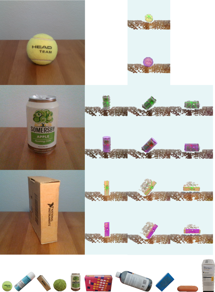
Ten able-bodied adults (24.53.9 years old) were recruited to test the developed prototype, and the experimental protocol was approved by the Research Ethics Committee for North Jutland (N-20190036). All participants gave their written consent prior to starting the experiment. The subjects performed a set of pick and place tasks. A total of ten objects were selected for the experiment such that all geometric shape categories were included: spherical (two), cylindrical (four), and cuboid (four) objects. Their respective grasping sizes varied from 35 mm to 85 mm. Each of the four cylinder and cuboid objects was placed in distinct orientations: upright, laying down, tilted to left, and tilted to the right. To challenge the system, the objects were presented to the participants in an order which forced the prosthesis to rotate its wrist DOF, avoiding thereby similar consecutive grasp orientations. The grasping sequence of ten object (Fig. 6, bottom) was repeated for five times (blocks).
The performance of the laser scanning approach was compared against the benchmark system that processed the full point cloud [10]. The only difference with respect to [10] was that the hand preshaping was not continuous but triggered by the user, to mimic the approach in the present prototype. When using the benchmark system, the participants did not receive vibrotactile feedback since it was enough for the user to aim in the vicinity of the object, and hence precise aiming was not required. The participants tested both systems in randomized order following the same protocol.
The experimenter instructed the participants to wait for the voice command and then 1) move the prosthesis towards the target object, 2) trigger the automatic controller to preshape the hand, 3) take over the control, and 3) close the hand, grasp the object and move it to the marked area (0.5 m from the initial position). In case the object slipped after the participant took over the control of the prosthesis, the trial was repeated. The outcome measure to characterize the performance was the Time to Accomplish the Task (TAT), defined as the time interval from the moment the participant started moving towards the object until the object was released in the designated ”drop” zone. Note that, whenever the automatically adjusted hand configuration was wrong, the subjects had to step back and trigger the automatic controller again, which then led to longer TAT. To assess the performance of the computer vision pipeline, we have computed the reconstruction accuracy as the percent of objects whose model was correctly estimated as well as the error in estimating the object size, for both novel prototype and the benchmark.
II-D Data Analyses
The median TAT across objects was calculated for each participant in block. The results of a Shapiro-Wilk test revealed that the data was not normally distributed, and therefore, the Friedman test was used to assess if the performance of the two systems changed across blocks. The post-hoc pairwise comparisons were performed using Wilcoxon signed rank tests (statistical significance of ), with Bonferroni correction. Wilcoxon signed rank test was also used to compare the performance between the two systems in each block. The results are reported in the following Section as M{IQR}: median and interquartile range, respectively.
III Results
Across all trials (N = 100) the novel prototype successfully reconstructed: 98.6% spherical objects, 91.4% cylindrical objects, 88.6% cuboid objects, compared to 100%, 95% and 100%, for the benchmark approach, respectively. Considering the objects individually, the prototype system correctly estimated the object model in 90% of cases for all objects apart from the left-tilted cylindrical object (82.9%) and for the vertical cuboid object (60.0%), which were the largest objects in the set ( mm).
The mean absolute error in estimating the object size was mm ( % of actual object size) for the prototype, and mm ( % of actual object size) for the benchmark system. The mean absolute error in the estimation of object orientation was °for both systems.
The representative examples of object reconstructions from the laser scans for some objects used in the experiment are provided in Fig. 6, top. The figure shows the scan lines and the estimated object models. The cuboid and cylindrical objects are placed in three different orientations to demonstrate that the system can estimate object parameters (model, size and orientation) regardless of the current prosthesis configuration or object posture. In the case of the cylindrical object, the laser scans generated when the object was placed vertically and horizontally produce a line, a circle and two ellipses. In contrast, for the tilted cylinder, the scans are obtained from fitting four ellipse primitives. The cuboid object, however, was reconstructed using four line primitives regardless of orientation. The lines were placed across its frontal face to which the participant aimed at, but he/she could have selected any other face to be target for grasping (e.g., approaching the object from the top side).
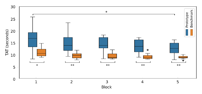
Figure 7 presents the TAT across blocks for both approaches. The median TAT decreased for both approaches, from 16.7{6.0}s to 12.5{4.0}s for the prototype (25% of reduction) and from 10.4{2.9}s to 8.8{0.7}s for the benchmark (16% reduction). The statistically significant improvement was, however, found only for the laser scanning approach, where the TAT in the fifth block was significantly smaller () that the TAT in the first block. The benchmark method consistently outperformed the laser scanning, as the participants were significantly faster with that system in each block. Nevertheless, the difference in TAT between the two systems consistently reduced across blocks, from 6.3 s in the first to 3.7 s in the last block, and this reduction was statistically significant ( or ).
IV Discussion
This study proposed and evaluated a new system for semi-autonomous prosthesis control using depth sensing with the sensor placed on the hand. While the previous works relied on the computationally demanding processing of the full point clouds [5, 15, 14, 10], the presented approach involves minimal data retrieved in the form of multiple laser scans. We have first explored what can be achieved with different number of scans, from 1 to 4, concluding that only 4 lines can ensure the reconstruction in all cases of interest. A method was then developed that can reconstruct object shape, size and orientation from the four scans using simple geometry and fitting of 2-D geometric primitives such as circles, ellipses or lines, instead of explicit 3-D models, which are used in the state of the art [5, 15, 14, 10].
The aim of the present study was to show the feasibility of the reconstruction with the minimal data set, establish the limitations regarding the number of laser scans, develop the methods and demonstrate that they can be translated into a functional prototype. Importantly, the conducted experiments demonstrated that the developed prototype performed reliably and robustly as it allowed the participants to handle a set of objects of different shapes, sizes and orientations. This is an important step towards the clinical applicability of the semi-autonomous approaches for prosthesis control. Minimizing the amount of data required to estimate object properties can potentially allow using a simpler sensor, with smaller size, lower cost and power consumption, while also reducing the memory and computational resources that are needed to store and process the data. All of these are important prerequisites considering that a prosthesis is a wearable system with strict constraints in terms of size, power and computation. To achieve the flexibility in testing, the laser scans were simulated using a depth camera, but the idea is that the final solution is based on a potentially custom-made LiDAR sensor. Not only that this will make the system more compact but it will also improve the quality of the scans. The sensor could be integrated into the hand/socket and it could be even further simplified by using less than four scans, however, with the loss of functionality and hence more limited assistance to the prosthesis user (as explained in Section II-A1).
Although crossing lasers have been previously employed for 3-D reconstruction using projected light [26, 27], laser interference is a known challenge in the time-of-flight technology [28]. However, mutual interference between laser scanners occurs mainly for co-planar setups [29], which is not the case in our hypothetical implementation. The interference can be either direct, when two different laser scanners face each other, or indirect when the light of one emitter is reflected and scattered from an object towards a second receiver [29]. The scanning system for a prosthesis could be built using a sensor capable of emitting in multiple planes while using only a single detector. To avoid the indirect interference, in such a system, different laser light scans could be pulsed alternatively to reduce the light scattering effect (which may already be reduced as the laser scanners are not co-planar [29]). Most laser interference problems are due to multiple off-the-shelf laser scanners using the same wavelength, usually at 905 nm as imposed by their manufacturer [30]. Hence, if the laser scanners flash at different near-infrared wavelengths, the indirect interference can be mitigated [31].
The experimental assessment showed that the system could correctly reconstruct a set of daily life objects and that the participants could use the prototype to accomplish a functional pick and place task. Contrary to our initial hypothesis, the subjects were slower when using the novel prototype compared to the benchmark system, even after some training, but the difference was overall small. The difference in TAT consistently decreased across the blocks reaching 4 s at the end of the experiment. The learning to use the system was more expressed for the laser scanning prototype and hence it remains to be seen if the additional use of the system would further diminish the difference with respect to the benchmark. The lower performance of the novel prototype is mostly due to the need for precise aiming at the object, as the full reconstruction is possible only when the optical z-axis is within the object. The benchmark system, on the other side, is more robust, because it only requires that the object is within the indicated volume of space in front of the prosthesis, and hence, the participants only had to aim in the vicinity of the target object [10]. To facilitate the aiming step when using the novel prototype, vibrotactile feedback was introduced and, despite the training did improve the efficiency of the aiming, the time to accomplish the task was still higher compared to the benchmark. Sensory feedback has been used before to improve the performance in grasping for systems using vision-based semi-autonomous prosthesis control [5]. However, the feedback was based on a visual display (e.g., AR glasses [5, 14], blinking LEDs [12]) and not tactile technologies as in the present study. Tactile feedback has advantages as it can be integrated into the prosthesis, and it does not load the visual sense, which can be already overloaded when using a prosthesis [5, 14]. An alternative approach to simplify aiming would be to add a guiding laser pointer, such as that presented in Dosen et al. [4]. The advantage of tactile feedback is that it is silent and non-intrusive (e.g., the laser pointer is visible).
The estimation accuracy of the computer vision pipeline was also somewhat worse compared to the benchmark, but this was expected as the difference in the amount of input data is substantial ( 700300 vs. 53002100 data points, on average, respectively, for a resolution of 424x240 px). The amount of data is likely to increase linearly for the prototype with an increase in resolution, whereas it increases quadratically for the benchmark. Nevertheless, the relative differences were not too large. The success rate in shape estimation was 1-11% lower for the prototype depending on the object type. The difference in size and orientation errors was 5% higher for the prototype but absent for orientation error (2% for both), respectively. As the proposed system uses less data for reconstructing the three main object shapes, it is also slightly less accurate when estimating the sizes of smaller objects. Cylindrical and spherical objects with small diameter seem to be the most difficult to reconstruct. This limitation can be explained by the fact that smaller objects lead to a reduced amount of points in the partial circular or elliptical cuts. If the scans are of such a low quality, they can be better fitted by a line primitive instead of the supposed circle or ellipse model. Importantly, the precision of estimation and modeling is likely to be substantially improved when using real laser scanners, as they will provide scans of much higher quality compared to those obtained through simulation.
In terms of computational time, the two systems performed similarly. On average, the prototype and the benchmark took 138 ms (7 Hz) and 75 ms (13 Hz) per reconstruction, respectively, and presented the refresh rates in the ranges of [4,17] Hz and [9,18] Hz. Despite using less data, the computational pipeline of the laser scanning approach was not optimized in the present study. The main goal was instead to prove the feasibility of reconstructing the objects using minimal data. The optimization of the pipeline to properly capitalize on the used of less data and simpler processing remains a future work.
The present study demonstrates that the object properties can be indeed successfully estimated from minimal depth data. This implies the feasibility of on-board depth-based prosthesis controllers to a achieve a fully self-contained system, where a combination of laser scanners can be used instead of a depth camera. The next step of this research is to test a system using real laser scanners instead of a simulated device as presented.
V Conclusion
The present study proposes a novel method to reconstruct object properties for automatic control of prosthesis grasping using minimal depth data and simple processing. The method was then used to implement a semi-autonomous controller with vibrotactile feedback to assist the user when aiming towards the target object. The prototype was tested on ten able-bodied subjects and the results demonstrated that the system was robust and reliable, although still somewhat worse compared to the benchmark that used the full depth data and complex processing. Nevertheless, the participants showed statistically significant progress across blocks, which might imply that the learning curve of such a setup may be longer when compared to the benchmark, mainly due to the need for feedback-driven aiming. Overall, the present study shows the feasibility of a semi-autonomous controller using minimal data that can be provided by a simple sensing system convenient for embedded implementation.
[Implementing an Ellipse3D for RANSAC fitting] An ellipse 3-D sample consensus model was implemented in the Point Cloud Library [24], and the proposed code has been added to the open repository. An example is also available at https://github.com/mnobrecastro/pcl-ellipse-fitting.
The iterative process of a sample consensus algorithm, such as the RANSAC [23], using a 3-D circle or ellipse geometric model typically involves the following steps: 1) randomly select k (k=3 or k=6, respectively) inlier points from the set to initialize the algorithm; 2) define the normal vector to the average plane containing those points and pick one of them; 3) calculate the projection of all k points onto that plane; 4) fit the geometric model; 5) measure the distances from the remaining points in the set to the geometric model; 6) evaluate whether each of those points is an inlier or outlier based on a preset distance threshold.
For an ellipse, Step 4) can be accomplished through a linear least-squares ellipse fitting during Step 4). This method presented by Fitzgibbon et al. [32] can handle noisy data and provides the six parameters of the conic equation of an ellipse by solving a constrained generalized eigen system. The model is then converted to a parametric model with 11 parameters: the center point (three); the semi-major/minor distances along the local x- and y-axis of the ellipse (two); the normal to the plane containing the ellipse (three); and the local x-axis of the ellipse (three). Afterwards, in our implementation, Step 5) first identifies to which ellipse quadrant each point relatively belongs. Then, it performs a golden-section line search [33] on the ellipse points belonging to that quadrant in order to find the shortest distance to the ellipse.
References
- [1] S. Salminger, H. Stino, L. H. Pichler, C. Gstoettner, A. Sturma, J. A. Mayer, M. Szivak, and O. C. Aszmann, “Current rates of prosthetic usage in upper-limb amputees – have innovations had an impact on device acceptance?” Disability and Rehabilitation, vol. 44, no. 14, pp. 3708–3713, 2022.
- [2] J. M. Hahne, M. A. Schweisfurth, M. Koppe, and D. Farina, “Simultaneous control of multiple functions of bionic hand prostheses: Performance and robustness in end users,” Science Robotics, vol. 3, no. 19, p. eaat3630, 2018.
- [3] A. Dillen, D. Steckelmacher, K. Efthymiadis, K. Langlois, A. De Beir, U. Marusic, B. Vanderborght, A. Nowé, R. Meeusen, F. Ghaffari, O. Romain, and K. De Pauw, “Deep learning for biosignal control: insights from basic to real-time methods with recommendations,” Journal of Neural Engineering, vol. 19, no. 1, p. 011003, 2022.
- [4] S. Došen, C. Cipriani, M. Kostić, M. Controzzi, M. C. Carrozza, and D. B. Popović, “Cognitive vision system for control of dexterous prosthetic hands: experimental evaluation,” Journal of neuroengineering and rehabilitation, vol. 7, no. 1, p. 42, 2010.
- [5] M. Markovic, S. Došen, C. Cipriani, D. Popovic, and D. Farina, “Stereovision and augmented reality for closed-loop control of grasping in hand prostheses,” Journal of Neural Engineering, vol. 11, no. 4, p. 046001, 2014.
- [6] G. Ghazaei, A. Alameer, P. Degenaar, G. Morgan, and K. Nazarpour, “Deep learning-based artificial vision for grasp classification in myoelectric hands,” J. Neural Eng., vol. 14, no. 3, p. 036025, 2017.
- [7] M. Gardner, C. S. Mancero Castillo, S. Wilson, D. Farina, E. Burdet, B. C. Khoo, S. F. Atashzar, and R. Vaidyanathan, “A multimodal intention detection sensor suite for shared autonomy of upper-limb robotic prostheses,” Sensors, vol. 20, no. 21, p. 6097, 2020.
- [8] B. Zhong, H. Huang, and E. Lobaton, “Reliable vision-based grasping target recognition for upper limb prostheses,” IEEE Transactions on Cybernetics, vol. 52, no. 3, pp. 1750–1762, 2020.
- [9] C. Shi, D. Yang, J. Zhao, and H. Liu, “Computer vision-based grasp pattern recognition with application to myoelectric control of dexterous hand prosthesis,” IEEE Transactions on Neural Systems and Rehabilitation Engineering, vol. 28, no. 9, pp. 2090–2099, 2020.
- [10] M. N. Castro and S. Dosen, “Continuous semi-autonomous prosthesis control using a depth sensor on the hand,” Frontiers in Neurorobotics, vol. 16, no. March, pp. 1–17, 2022.
- [11] J. Starke, P. Weiner, M. Crell, and T. Asfour, “Semi-autonomous control of prosthetic hands based on multimodal sensing, human grasp demonstration and user intention,” Robotics and Autonomous Systems, p. 104123, 2022.
- [12] M. C. F. Castro, W. C. Pinheiro, and G. Rigolin, “A hybrid 3d printed hand prosthesis prototype based on semg and a fully embedded computer vision system,” Frontiers in Neurorobotics, vol. 15, pp. 1–11, 2022.
- [13] F. Vasile, E. Maiettini, G. Pasquale, A. Florio, N. Boccardo, and L. Natale, “Grasp pre-shape selection by synthetic training: Eye-in-hand shared control on the hannes prosthesis,” 2022.
- [14] J. Mouchoux, S. Carisi, S. Došen, D. Farina, A. F. Schilling, and M. Markovic, “Artificial perception and semiautonomous control in myoelectric hand prostheses increases performance and decreases effort,” IEEE Transactions on Robotics, pp. 1–15, 2021.
- [15] M. Markovic, S. Došen, D. Popovic, B. Graimann, and D. Farina, “Sensor fusion and computer vision for context-aware control of a multi degree-of-freedom prosthesis,” Journal of neural engineering, vol. 12, no. 6, p. 066022, 2015.
- [16] F. Hundhausen, R. Grimm, L. Stieber, and T. Asfour, “Fast reactive grasping with in-finger vision and in-hand fpga-accelerated cnns,” in 2021 IEEE/RSJ International Conference on Intelligent Robots and Systems (IROS). IEEE, 2021, pp. 6825–6832.
- [17] F. Kallasi, D. L. Rizzini, and S. Caselli, “Fast keypoint features from laser scanner for robot localization and mapping,” IEEE Robotics and Automation Letters, vol. 1, no. 1, pp. 176–183, 2016.
- [18] T. Yamada, T. Ito, and A. Ohya, “Detection of road surface damage using mobile robot equipped with 2d laser scanner,” in Proceedings of the 2013 IEEE/SICE International Symposium on System Integration. IEEE, 2013, pp. 250–256.
- [19] A. Mogelmose and T. B. Moeslund, “Analyzing wheels of vehicles in motion using laser scanning,” in 2016 IEEE Conference on Computer Vision and Pattern Recognition Workshops (CVPRW). IEEE, 2016, pp. 1601–1608.
- [20] J. Jutila, K. Kannas, and A. Visala, “Tree measurement in forest by 2d laser scanning,” in 2007 International Symposium on Computational Intelligence in Robotics and Automation. IEEE, 2007, pp. 491–496.
- [21] J. Butterfass, G. Hirzinger, S. Knoch, and H. Liu, “Dlr’s multisensory articulated hand. i. hard- and software architecture,” in Proceedings. 1998 IEEE International Conference on Robotics and Automation, vol. 3. IEEE, 1998, pp. 2081–2086.
- [22] M. Quigley, C. Salisbury, A. Y. Ng, and J. K. Salisbury, “Mechatronic design of an integrated robotic hand,” International Journal of Robotics Research, vol. 33, no. 5, pp. 706–720, 2014.
- [23] M. A. Fischler and R. C. Bolles, “Random sample consensus: a paradigm for model fitting with applications to image analysis and automated cartography,” Communications of the ACM, vol. 24, no. 6, pp. 381–395, 1981.
- [24] R. B. Rusu and S. Cousins, “3D is here: Point Cloud Library (PCL),” in IEEE International Conference on Robotics and Automation (ICRA), Shanghai, China, 2011.
- [25] J. O’Rourke, Computational geometry in C, 2nd ed. Cambridge University Press, 1998.
- [26] R. Furukawa and H. Kawasaki, “Laser range scanner based on self-calibration techniques using coplanarities and metric constraints,” Computer Vision and Image Understanding, vol. 113, no. 11, pp. 1118–1129, 2009.
- [27] L. He, S. Wu, and C. Wu, “Robust laser stripe extraction for three-dimensional reconstruction based on a cross-structured light sensor,” Applied Optics, vol. 56, no. 4, p. 823, 2017.
- [28] P. F. McManamon, “Review of ladar: a historic, yet emerging, sensor technology with rich phenomenology,” Optical Engineering, vol. 51, no. 6, p. 060901, 2012.
- [29] G. Kim, J. Eom, S. Park, and Y. Park, “Occurrence and characteristics of mutual interference between lidar scanners,” in Photon Counting Applications 2015, I. Prochazka, R. Sobolewski, and R. B. James, Eds., vol. 9504, 2015, p. 95040K.
- [30] Y. Li and J. Ibanez-Guzman, “Lidar for autonomous driving: The principles, challenges, and trends for automotive lidar and perception systems,” IEEE Signal Processing Magazine, vol. 37, no. 4, pp. 50–61, 2020.
- [31] X. Sun, L. Zhang, Q. Zhang, and W. Zhang, “Si photonics for practical lidar solutions,” Applied Sciences (Switzerland), vol. 9, no. 20, 2019.
- [32] A. Fitzgibbon, M. Pilu, and R. Fisher, “Direct least square fitting of ellipses,” IEEE Transactions on Pattern Analysis and Machine Intelligence, vol. 21, no. 5, pp. 476–480, 1999.
- [33] J. S. Arora, Introduction to optimum design, 3rd ed. Elsevier, 2004.