XR-RF Imaging Enabled by Software-Defined Metasurfaces and Machine Learning: Foundational Vision, Technologies and Challenges
Abstract
We present a new approach to Extended Reality (XR), denoted as iCOPYWAVES, which seeks to offer naturally low-latency operation and cost effectiveness, overcoming the critical scalability issues faced by existing solutions. iCOPYWAVES is enabled by emerging PWEs, a recently proposed technology in wireless communications. Empowered by intelligent (meta)surfaces, PWEs transform the wave propagation phenomenon into a software-defined process. We leverage PWEs to: i) create, and then ii) selectively copy the scattered RF wavefront of an object from one location in space to another, where a machine learning module, accelerated by FPGAs, translates it to visual input for an XR headset using PWE-driven, RF imaging principles (XR-RF). This makes for an XR system whose operation is bounded in the physical-layer and, hence, has the prospects for minimal end-to-end latency. Over large distances, RF-to-fiber/fiber-to-RF is employed to provide intermediate connectivity. The paper provides a tutorial on the iCOPYWAVES system architecture and workflow. A proof-of-concept implementation via simulations is provided, demonstrating the reconstruction of challenging objects in iCOPYWAVES-produced computer graphics.
Index Terms:
Extended/Virtual/Augmented Reality, Software-Defined Networking, Wireless, XR-RF Imaging, Machine Learning, Propagation, Generative Adversarial Networks, Applications.I Introduction
Extended Reality (XR) is an emerging concept that includes spatial computing technologies such as Augmented Reality (AR), Mixed Reality (MR), and Virtual Reality (VR) [1, 2]. Users with smart glasses, smart phones or head-mounted displays can observe virtual content that does not exist in reality. XR will profoundly change our lives across many areas, e.g., entertainment, manufacturing, sports, and remote healthcare. For example, users with MR smart glasses, e.g., Microsoft HoloLens, can share their real-time view with experts and receive step-by-step remote assistance, which can significantly improve worker productivity.
Motion-to-photon latency is a critical parameter in XR applications. For example, when a VR gaming user presses a button on a controller, the VR virtual content has to be rendered based on this motion. The latency from motion to display should be lower than ms to avoid motion sickness [3, 4]. Currently, the main contributor to latency in XR systems is the need for frequent and successive crossings of all the Open Systems Interconnection (OSI) model layers [3, 4]. The information from a multitude of sensors (cameras, lidars, sensors, actuators, microphones) needs to be gathered in highly-confined timeslots to a local server near a user. This information necessarily traverses a network, is queued, and processed in very tight time windows, necessitating high throughput wireless and wired networking infrastructure supporting state of the art time-sensitive protocols, and high throughput computing at the server side, commonly utilizing multiple, expensive CPUs and GPUs. Depending on the XR targeted scale, the infrastructure requirements are such that only large companies with datacenter infrastructure near the end user can uphold them. Even at such cases, and apart from the commitment of technological resources (capital expenses), the operational expenses, such as the associated energy footprint, can be exorbitant [3, 4].
XR is in urgent need of innovative solutions which provide low-latency operation and cost-effectiveness. The present work seeks to explore this path and meet the stringent performance requirements based on two technological pillars, namely Radio Frequency (RF) imaging and Programmable Wireless Environments (PWEs). RF imaging is a direction stemming from physics, where RF waves are used for detecting the location and shape of an object, as opposed to visible light imaging [5, 6, 7, 8]. Commonly, a single-frequency RF wave source emits waves upon a 3D scene (much like the sunlight illuminates the objects around us), and the scattered waves are collected by an array of receivers. The captured wavefront is then mapped to the visual representation of the object through analytical insights or machine learning approaches. The second pillar of our proposal are PWEs, which constitute a recent direction in wireless communications [9, 10], which is already expected to be massively deployed in multiple environments within 6G [11]. PWEs transform the wireless propagation phenomenon into a software-defined resource. PWEs are created by coating all major surfaces in a space, such as walls and ceilings in a floorplan, with programmable metasurfaces, also known as software-defined metasurfaces (SDMs). In the broad sense, metasurfaces are thin arrays of electromagnetically small elements, the so-called meta-atoms, that are made tunable most commonly by incorporating tunable impedance elements in general [12, 13]. PIN diodes [14, 15, 16, 17, 18, 19, 20, 21] (common), MicroElectroMechanical Switches [22] and ASICs (more exotic) [23, 24] (and others [25, 26, 27, 28, 29, 30, 31]) are some popular circuit components employed to provide tunable impedance and even more advanced capabilities. Metasurfaces are essentially engineered materials that have customized and user-variable interaction with impinging electromagnetic (EM) waves. Anomalous steering, absorption, polarization control are exemplary manipulations performed by a metasurface to impinging waves. Metasurfaces are created with an abundant array of alternative cost-effective processes ranging, e.g., from standard printed circuit boards (3D), to 3D printing and computerized numerical control (CNC) milling [32, 33, 34]. Moreover, PWEs abstract the underlying complex physics and allow the tuning of a massive set of metasurfaces, inspired by the Software-Defined Networking (SDN) paradigm to achieve operational logic-physics separation [35, 36].
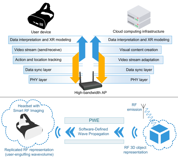
Based on these available components, the present study contributes a new XR approach called iCOPYWAVES (intelligent copying of RF wavefronts/wavevolumes), which simplifies the XR architecture as shown in Fig. 1. Through a physical layer-bounded operation, iCOPYWAVES favors cost-effectiveness, and ideally allows for nearly-speed-of-light end-to-end operation, favoring scalability through naturally low-latency operation. The core-idea is to use PWEs to intelligently copy an RF wavefront, or an RF wavevolume, from one location to another within a space. The RF wavevolume replication, i.e., copying a 3D EM field to the location of an RF imaging device, engulfing it within the replicated field, is of particular interest. This would allow the RF imaging device (envisioned to be embedded in a user’s XR headset in the future), to operate without the need for gyroscopes and location tracking sensors. As the user, e.g., rotates his/her head, an RF imaging device embedded on his/her headset continuously reads the corresponding part of the wavevolume, yielding the proper view of the 3D object, even completely without assistance from sensory devices or external computing elements: Machine learning-empowered RF imaging reconstructs the 3D object using the copied wavefront as input, and inserts it into an XR application setting in the proper format.
In summary, this paper presents a tutorial on the architecture and workflow of iCOPYWAVES. Moreover, iCOPYWAVES is well-aligned with forthcoming 6G infrastructure, which it reuses without further requirements. Furthermore, the paper identifies and discusses challenges involved in the end-to-end system implementation, covering all aspects, from the advanced manipulation of EM waves provided by metasurfaces and the PWE control algorithms necessary to implement wavefront copying, to attaining efficient RF imaging reconstruction and insertion onto an XR setting. Moreover, the proposed system advances the concept of RF imaging to producing precise computer graphics for XR, i.e., XR-RF, as opposed to the coarse imaging capabilities of RF imaging in the traditional use of the term [37, 38, 39, 40, 41, 42]. Promising results in this sense are also provided via a simulation-driven implementation of the iCOPYWAVES system, which includes precise simulation of the wireless propagation aspect and a machine learning component trained to produce computer graphics in a challenging setup.
The remainder of this paper is organized as follows. Section II surveys the background work on XR systems, RF Imaging and PWEs. Section III presents the iCOPYWAVES system architecture. Evaluation via simulations follows in Section IV. Research challenges are highlighted in Section V, and the paper is concluded in Section VI.
II State-of-the-art and limitations
The great barrier that stands between current technology and remote XR presence is the extremely stringent motion-to-photon latency, which should not exceed 20 in order to avoid motion sickness and enable lifelike experiences [43, 44].
The motion-to-photon latency includes any delay incurred by motion capture, encoding, communication, sensor fusion, processing, actuator control, rendering and decoding of each frame. The different tasks that lie on the critical path of the motion-to-photon latency, and their associated timings include [45, 46]:
-
•
Sensor sampling and synchronization: 1-5 (high-end tracking).
-
•
Scene rendering: 4-16 (for 60Hz display).
-
•
Display scanning: 2-16 (60Hz, depending on the employed technology).
-
•
Photon emission: 1-2 (depends on employed technology).
These factors on their own can already violate the 20 total time frame. Moreover, the latency of the network that interconnects multiple users is not even taken into consideration in these factors, and can introduce additional latency in the range of on its own. (Notice that a part of this latency is unavoidable, and stems from the finite speed of EM wave propagation. Thus, notice that this range can be even overly optimistic for world-wide communication).
In AR, processes such as object identification, registration, or retrieval of data already take considerable time [1]; whereas, in VR, the sheer processing throughput required by the video stream is highly taxing. On top of them, the display scanning and photon launching further contribute to this delay. Even when considering high-end hardware and processing techniques, these tasks will take 5 to 8 . All in all, this leaves about 12 to 15 for the transmission, processing and reception of information, which are the key enabling functionalities of remote XR presence.
The OSI layer crossing and the network latency combined is a barrier that completely prevents the development of practical real-time remote XR presence applications and will continue to be so unless it is reduced at least tenfold. This constitutes an important shortcoming and reduces the XR potential. Consequently, XR is currently a largely individual experience, and at best allows participation of multiple locally connected users. Bringing XR to the next level to enable lifelike interactive and human-centric remote presence will require significant scientific and technological advances.
In sharp contrast, iCOPYWAVES is a new approach to the XR concept. With the combination of RF imaging and PWEs, the proposed system requires no visual or gyroscopic sensory equipment, especially in the wavevolume replication case. This means that data serialization and communication via networking is required only in the remote site case, and can be avoided even within, e.g., a large building or a mall. Moreover, even in the networking case, the information that needs to be serialized is simple waveforms that need not be understood or logically processed. Instead, these wavefronts can be sampled and send over the wire directly, or even undergo a physical-to-physical signal conversion with latency, such as wireless-to-optical and optical-to-wireless.
Here we also make note of existing network standards that also offer minimal latency. Third Generation Partnership Project (3GPP) coined the term ultra-reliable low-latency communications (URLLC) [47], which defines a target latency of 1 at a packet loss ratio of for 32-byte packets on the wireless radio access network (RAN) segment [48]. Another enabler is deterministic networking (DetNet) [49], coined by Internet Engineering Task Force (IETF), guaranteeing specific latency and jitter bounds for packets routed through the core network segment.
II-A Programmable Wireless Environments with Software-Defined Metasurfaces
PWEs are end-to-end systems for controlling a wide array of metasurface types [50, 51, 52, 53, 54, 55], in order to apply deterministic control over the wireless propagation process [9]. A PWE is created by coating planar objects–such as walls and ceilings in an indoor environment–with rectangular and individually addressable metasurface panels with inter-networking capabilities [56, 36]. The latter allows a central server to connect to any metasurface unit, read its state and deploy a new EM function in real-time and in a standards-compliant manner. PWEs seek to provide a full protocol stack, clarifying the physical, network, control and application layers of the complete system [56]. Moreover, PWEs leverage an SDN-inspired separation of concerns and [56]:
-
1.
model the metasurface wave manipulation types (e.g., steer, split, absorb, etc.) as software functions invokable via an application programming interface. This makes the metasurface capabilities accessible to software developers at large, without requirements for in-depth knowledge of the underlying physics.
-
2.
Maintain an abstracted, graph-based view of the system state, transforming the PWE configuration optimization problem (i.e., how to tune each SDM to serve a set of wireless devices), into a classic resource slicing problem.
Moreover, PWEs define the system workflow, from the discovery of a PWE by a user device, to the statement of objectives and to its service, in a generalized multi-tile, multi-use setting [57]. PWE as a generic control system goes beyond wireless communications, exerting deterministic control over mechanical, acoustic and thermal propagation [36, 58]. Within the EM domain the PWE focus is to craft EM vector field distributions, and not only reductions, such as scalar power levels. To this end, PWEs treat metasurfaces in their most generic way of operation, i.e., converters of surface current distributions. Impinging waves create a surface distribution “A” upon an intelligent surface, and embedded control elements convert it to a state “B” that yields the required EM field as a global response. This model is denoted as software-defined metasurfaces (SDMs). Finally, PWEs are created by massive deployments of SDMs in a space, covering all major surfaces within it in a tiled sense, e.g., the ceiling and all the walls in an indoors setting. The overall operation is typically in the near-field, in the sense that PWE SDMs are not modeled as concentrated at a single point in space [57].
Smart radio environments (SREs) constitute a concept that focuses on the signal processing aspects of wireless communications, and especially in conjunction with AI techniques [59]. The channel control type is stochastic and the enabling technology are phase shifter grids, which are commonly denoted as reflectarrays or intelligent reflective surfaces (LIS, IRS or RIS) [10, 60]. SREs typically assume very few RIS units, sparsely deployed within a space, and in the far field in general. Based on these premises, the goal is to iteratively optimize the phase shifter states (free variables) in order to maximize a scalar quantity representing a wireless communication objective (fitness function) [60]. Additionally, given the theoretical signal processing focus of smart radio environments, the required protocols, system workflows and integration-to-infrastructure processes are commonly left undefined in the literature, i.e., inherently assuming that an underlying PWE or related system stack or similar is in place. In a layered sense, PWE is a top-to-bottom systemic approach, while the smart radio environment is a layer-specific study (channel modeling with RIS and applications).
PWEs and SREs are recent directions in long-standing but disparate research efforts towards controlling the wireless propagation environment, as opposed to the device end-points [61, 62, 63, 64]. Approaches have explored the placement of passive reflectors to increase coverage in a space [63], to employing reflectarrays as active alternatives [61, 62, 64]. The SRE direction consolidated the latter approach, and established the term RIS to denote half-wavelength reflectarrays that are employed for communication purposes [65]. PWEs constituted a distinct approach towards deterministic propagation control, and a departure from the stochastic principles of preceding efforts. As such, the uses of PWE go beyond communications and electromagnetism, exemplary enabling deployments within high-precision imaging devices in order to either increase their efficiency, or counter-balance manufacturing imperfections [66].
As such, PWEs and SREs have conceptual similarities, but also vast differences regarding the capabilities and intended uses of each technology. (Moreover, the terminology about SDMs/PWEs and RIS/SREs is still in convergence, which can give rise to inaccurate classifications in the literature). In this paper, we clarify that iCOPYWAVES requires deterministic control over the EM propagation, as well as a full-stack implementation in order to operate:
Specifically within the EM propagation control field, both SREs and PWEs have been successful in mitigating path loss, fading and Doppler effects at large [12, 67, 51, 68, 59, 10], albeit at different settings, overall costs and varying degrees of efficiency. Moreover, the existing works treat device-to-device communications only, which corresponds to a point-to-point wave replication. In contrast, iCOPYWAVES studies the complete wavefront and wavevolume replication, i.e., in 2D and 3D respectively, and its applications to XR imaging.
Therefore, the remainder of this paper employs the terms PWE and SDMs.
II-B From RF Imaging to XR-RF Imaging
RF imaging is the general process of detecting attributes of hidden, embedded or remote objects using RF waves (i.e., roughly within MHz and GHz). RF Imaging can either strive for precision, attempting to detect geometrical parameters such as shape, size and location of an object, or for quantitative parameters, such as coarse composition existence of features (such as cracks in a concrete slab), etc. Synthetic aperture radars and ground-penetrating radars constitute some well-known RF imaging approaches [5].
By leveraging metasurfaces, three-dimensional RF imaging beyond the diffraction limit was made possible, with low-profile apertures, without the need of lenses, moving parts or phase shifters, reducing the cost, size, complexity and power demands of conventional imaging technology [69, 70, 71]. Tunable millimetre metasurfaces have been so far implemented to produce spatially diverse patterns in the vast microwave and low THz spectrum [72, 73, 74, 75]. Approaches have striven for task-specific and low latency RF Imaging, i.e., employing metasurfaces to illuminate scenes in a targeted effort to look for particular objects from a given set of possible templates [37, 38, 39]. The low-latency aspect has been studied without taking into account the presence of a protocol stack, such as PWE, which is necessary to provide standards-compliant interconnectivity. Task-specificity in RF illumination can also be considered as the next step from random illumination [41, 42]. The common denominator of these state of the art approaches in RF-Imaging is the coarse quality of the end-outcome. Crisp graphics required for XR is not a possibility due to the inherent limitation of the emploed technological assumptions, essentially when employed in conjunction with RIS/SREs for the reasons detailed in Section II-A.
Moreover, it is a well-known fact that the resolution of RF imaging in its simplest form, i.e., i) employing a single RF source, ii) based on the amplitude of the received signals only, and iii) using analytical formulas to perform the image reconstruction, is defined by the employed wavelength. Under such conditions, high-resolution RF imaging would require high RF frequencies, e.g., at least GHz. Interferometric synthetic-aperture radar approaches can mitigate this limitation by employing phase and amplitude RF processing techniques, operating within the GHz range [76]. For instance, it has been shown that the achievable resolution in a reverberant environment as opposed to free space is orders of magnitude better because the reverberation provides a generalized interferometric sensitivity. This point was also proved via experiments with a RIS/SRE targeted at localization [77].
In differentiation, the PWEs employed in the iCOPYWAVES are also used for accurately manipulating the RF wavefront scattered by a 3D object (i.e., apart from its replication), and essentially act as spatially distributed synthetic-aperture radar system. In other words, via PWEs the received wavefronts are optimized for imaging, while unwanted effects (such as sidelobes) are canceled out or driven away from the RF receiver. Moreover, the wavefront replication approach means that a high-quality RF receiving device can be potentially shared for XR imaging tasks. Regarding the relation of iCOPYWAVES to task-specific illumination, the proposed XR approach is intended to be generic and objective towards the visualized scene, and not task-specific, which could potentially lead to biased XR visualization. However, task specificity can be attained by programming the PWE accordingly (e.g., copying targeted aspects of a wavefront), or by using machine learning modules specifically trained for the task in mind. Moreover, the paper shows that machine learning approaches can learn to perform a wavefront processing that is more complex than analytical formulas, which are inherently limited by human or physical intuition. As a result, the evaluation example included in the present study operated efficiently at just GHz.
Therefore, the proposed approach can promote a new direction for precise computer graphics produced by RF imaging, that can be used in XR systems, as opposed to the existing coarse RF imaging solutions. We denote this research goal as XR-RF imaging and employ it in the remainder of the paper. (In addition, it is noted that the present study bears no similarity to the field of holographic RIS/SRE [78], which refers to metasurfaces targeting precise electromagnetic control in their near field, and is irrelevant to XR, despite the similarity in their naming).
III The iCOPYWAVES approach to XR
iCOPYWAVES seeks to provide the necessary infrastructure for: i) creating RF wavefront representations of 3D objects, and ii) manipulating these RF wavefronts with the ease of a “copy-paste” functionality, thereby virtually transferring an RF representation of the original objects (their external structure and, perhaps, their internal composition as well) to remote locations.
System setup
We firstly describe the overall workflow of the iCOPYWAVES system in its operation phase, assuming the setup shown in Fig. 2. The setup uses a PWE comprising of a set of SDM, connected to an SDN controller for orchestrating them towards achieving a software-defined electromagnetic wave propagation. We note that the SDM and the SDN controller are considered to be parts of existing 5G/6G communications infrastructure. iCOPYWAVES simply adds another use of the same infrastructure for XR.
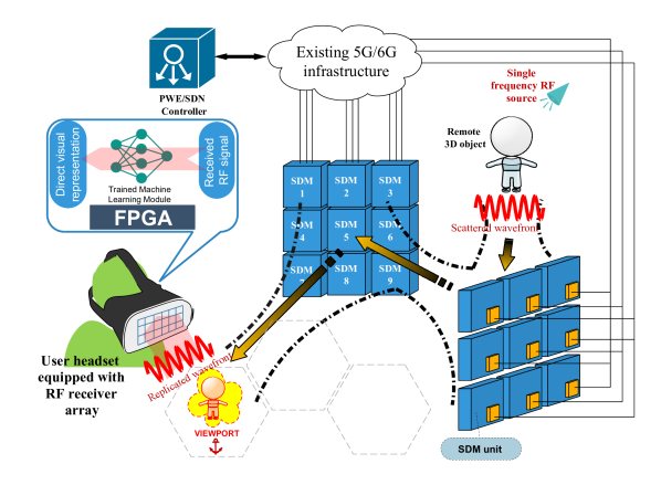
We proceed to describe the general end-to-end workflow of iCOPYWAVES. A new user enters the system, and associates himself with the existing PWE. (The reader is redirected to related studies for details on the user registration to the PWE, and the PWE deployment and initialization [56]). The new user is equipped with an iCOPYWAVES-compatible headset, which incorporates a MIMO antenna array, and an FPGA (Field-Programmable Gate Array) hosting a pre-trained machine learning component.
Remark 1.
In the scope of the present paper, Generative Adversarial Networks (GAN) are being used exclusively, but without loss in generality.
The GAN is trained to translate wavefronts impinging upon the MIMO antenna array into a visual XR outcome, such as a 3D cloud point, or Left/Right eye video streams (cf. Section III-A).
Remark 2.
The actual video format produced by the GAN can be adapted freely, to facilitate its direct integration to the underlying rendering workflow. For instance, setting the output format to be a cloudpoint ensures the 3D coherence of the reconstructed object. The choice of left/right video streams can be simpler to integrate in the XR experience, but may require extra processing to ensure coherence. In such cases, the extra processing power is also assumed to be offloaded to the FPGA.
In the meantime, a remote object receives impinging waves emitted by an RF source. In the setup shown in Fig. 2, the source is a cheap, single-frequency signal generator connected to a horn antenna. The waves scatter upon the remote 3D object, and arrive at SDM units around it. Then, it is the task of the PWE to copy the scattered wavefront around the vicinity of the XR user’s headset, essentially engulfing the headset within the replicated wavefront.
Remark 3.
The headset operates in a closed local loop, continuously translating the received RF wavefronts into visual outcomes, and without further communication with the SDN server. An additional benefit is that the user’s head rotations are automatically translated to the corresponding changes in the visual outcome.
The exact way of how the iCOPYWAVES operates to serve the user XR objectives may be adapted to the availability of a new user coarse localization system:
If a user localization system does not exist: The SDN controller sets up viewpoints where remote users are replicated. The new user must then walk and get closer to the replicated wavefront, which is much like what he/she would do for a real object. No information on the user’s location or mobility is required. The PWE configuration is viewed as a large optimization problem [79, 80, 81, 82, 60], and ensures that the multi-user viewpoints do not interfere. This can be accomplished with the wavefront routing logic shown in Fig. 2. In other words, the SDN controller solves the PWE configuration problem by finding air-routes that are disjoint from one another.
If a user localization system exists, then the SDN controller also knows the approximate location of the user device. This enables the controller to perform a versatile and fast rerouting of the EM wavefronts/wavevolumes [83, 9, 57, 84], thus following the user’s mobility pattern. This can allow for more immersive XR experiences, where, e.g., a remote avatar follows the user around, much like a tag-along character in a video-game. Notice that knowledge of the user’s position does not include the orientation of his/her head, but rather only his/her position on the floorplan in a relatively coarse X-Y basis, as shown in Fig. 2. The new user remains immersed in the replicated RF wavevolume. Thus, his/her head movements and minor X-Y dislocations are automatically translated to corresponding wavefront readings, allowing the machine learning module to produce the updated object view automatically.
Note that:
- •
-
•
RF waves do not carry coloring information. (They carry, however, material composition information which opens interesting new applications discussed later, in Section III-C). Smart coloring can be offloaded to the GAN (i.e., by training the GNA to artificially color objects, as demonstrated in Section IV), or be based on extra rendering steps, employing a single color photo of the 3D object. In both cases, the computational overhead is assumed to be offloaded to the FPGA.
We proceed to detail the various operation phases of the iCOPYWAVES system.
III-A The iCOPYWAVES GAN training phase
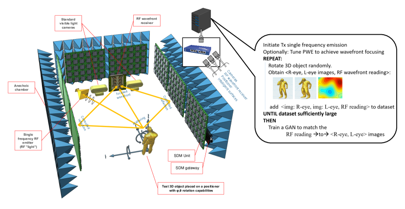
We consider the setup of Fig. 3, which consists of a test 3D object, a positioner (i.e., a device that can programmatically rotate an object in spherical coordinates), a set of standard visible light cameras, an RF wavefront receiver, a single frequency RF emitter, and a set of SDM units. All devices are connected to a central SDN controller and they are–optionally–located in a controlled electromagnetic environment, i.e., an anechoic chamber that mimics operation in free space [84].
The RF emitter acts as the “RF light” that illuminates the 3D object with EM waves. The 3D object scatters the waves, which are collected by the RF wavefront receiver. The SDM units assist by focusing more scattered waves on the RF wavefront receiver. The SDN controller collects the RF wavefront reading, as well as regular, visible light photos of the 3D object from a set of cameras. The process repeats as follows:
-
•
The positioner rotates the 3D object to a random rotation.
-
•
A data structure of is obtained and is added to a data set.
The process repeats until a sufficiently large number of data set entries has been obtained, in order to train a GAN to produce the photos from a given RF reading [85, 86]. The photos can then be used to reconstruct the 3D object into an XR setting.
Remark 4.
The anechoic chamber shown in Fig. 3 and onward is applicable to the GAN training phase, where accurate EM propagation control via the PWE is desirable. In real conditions, the GAN should be trained with artificial noise and interference patterns in a controlled environment first, before final deployment. We note that this is a measure of reducing the “free variables” at this stage of the iCOPYWAVES presentation. However, this does not preclude future GAN approaches that will be able to get trained in a drop-in fashion in real and uncontrollable conditions.
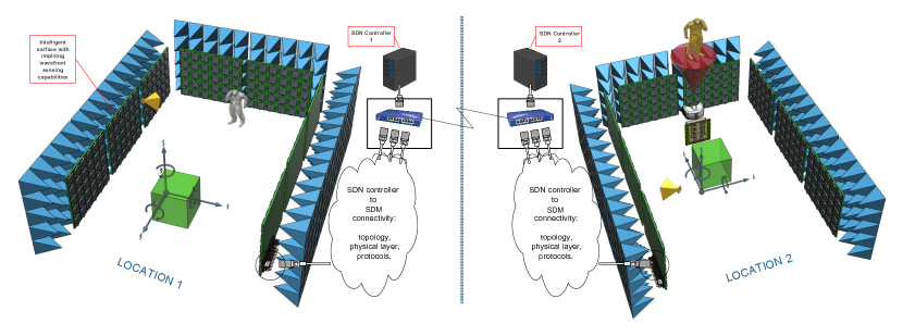
III-B The iCOPYWAVES operation phase I: Copying wavefronts/wavevolumes indoors
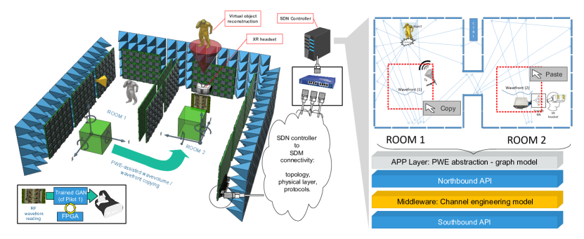
The first operation phase that we study, focuses on indoors settings, considering the setup of Fig. 4. (We assume that the outcomes of the training phase have been produced, and a trained GAN exists, which is able to reproduce a visual presentation of the 3D object from a corresponding RF wavefront).
The studied phase intends to provide the facilities for copying a wavevolume from one location to another on in proximity, without the need for over-the-wire data transmission. Therefore, the scenario of this phase intends to demonstrate a case where a virtual 3D object needs to be projected in relatively close vicinity to the original object, e.g., within a building.
In the studied phase we consider a space separated into two compartments, namely “room 1” and “room 2”, using SDM placed on the walls. The test 3D object in located in room 1, and is illuminated by the “RF light”. The PWE is then configured to replicate the scattered wavevolume from room 1 to room 2, where a receiving system exists. The receiving system consists of an RF wavefront reader collocated with the trained GAN, and an XR headset.
We note the following additional research tasks pertaining to the studied phase:
-
1.
The trained GAN outputs are assumed to be pre-processed as needed for feed into the XR system.
-
2.
The trained GAN/XR preprocessing system will be ported to an FPGA in order to minimize the overall processing time.
-
3.
The SDM units comprising the PWE will be connected to an SDN controller. The choice of the corresponding networking architecture, physical means, protocols and topology may be optimized for low-latency and low-cost. However, this assumed infrastructure can be part of the existing 5G/6G communications infrastructure, and not be deployed for the iCOPYWAVES system.
-
4.
The PWE control is exerted by a protocol stack implemented within an open SDN controller, thereby offering compatibility with the existing SDN ecosystem. The stack comprises [36]:
-
(a)
A northbound API that models the macroscopic behavior of the SDM units in the form of a library of callbacks. Examples include the definition of STEER(), SPLIT(), ABSORB(), PHASE_ALTER() function etc., to describe the interaction of an intelligent surface with an impinging EM wave. It is noted that each SDM comes with a configuration codebook, supplied during its quality check right after manufacturing. This codebook matches each possible callback to the corresponding configuration, i.e., the collective states of the SDM embedded control elements (e.g., PIN diodes).
-
(b)
A middleware in the form of a channel engineering model capturing the XR-RF imaging case. Notably, macrscopic PWE callbacks come with unintended microscopic side-effects. This can include unintended sidelobes during EM wave steering, as well as fading phenomena arising from SDM location imprecisions and imperfect control over the EM waves in general. The middleware provides a channel engineering model which will receive as inputs a set of activated northbound API callbacks, and will return as output the resulting, precise channel behavior.
-
(c)
A southbound API that provides connectivity compatibility between the SDN controller and the PWE control network.
-
(d)
A PWE abstraction layer, implemented on top of the northbound API, that provides a macroscopic model of the complete PWE system in the form of a graph. The objective is to provide a framework for decomposing high-level wave-copy commands into smaller, tractable problems, such as finding sets of paths within a graph that comply with a given set of criteria. Thus, a wavefront/wavevolume copy command will be treated as a set of point-to-point EM wave routing decisions.
-
(a)
Moreover, we stress that the XR workflow remains bounded within the physical layer, from the creating of a wavefront scattered from a 3D object, to its FPGA-driven translation to visual information.
III-C The iCOPYWAVES operation phase II: Copying wavefronts/wavevolumes remotely over the wire
We proceed to describe the remote operation of iCOPYWAVES in Figures 5 and 6. This phase extends the previous case with operation “over-the-wire”, in order to serve any remote location(s). As shown in Figures 5 and 6, we consider two separate locations, each with its own PWE controller. Location 1 contains the actual 3D object to be remotely projected at another location (2) containing the XR receiving system.
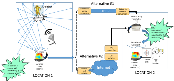
Interconnectivity is accomplished by taking advantage of the same SDN controller employed in phase I. Essentially, interconnecting the two controllers over the Internet establishes a pathway for altering the PWE of, e.g., location 2 based on input from location 1. Nonetheless, given that there is no actual means for direct wave propagation between the two locations, we require a means on converting the wavevolume of location 1 into a format that can be transferred over the wire interconnecting the two locations.
To this end, we consider two approaches for phase II:
Approach #1, shown in Fig. 5, remains cost-effective while maintaining the low-latency operation prospects. Moreover, it focuses explicitly of wavefront replication by using two extra antenna arrays. The first antenna array is placed anywhere in location 1. The PWE of location 1 is tasked with focusing the scattered waves from the 3D object over this antenna array. The second antenna array is placed anywhere within location 2, and it acts as a wavefront transmitter. The PWE in location 2 is tasked with replicating the wave emission from this transmitting antenna array to the vicinity of the user. Notice that, as shown in Fig. 2, the copied wavefront can act as a viewport. It can remain anchored to a specific place, and any user standing in front of it can see the remote object.
The wavefront read from the antenna array of location 1 can then be sampled, serialized and send to the transmitting antenna array of location 2. This can occur over the Internet, subject to the (uncontrollable) latency that this alternative entails. Another alternative is to employ direct RF-to-optical / optical-to-RF converters, as allowed by the available infrastructure [87]. In this approach, every element of the receiving antenna array is mapped directly to a optical light variations over a dedicated wavelength and travels at the speed of light along a fiber. The conversion itself is of direct, physical-to-physical nature, and has trivial latency.
Remark 5.
We note that this approach–as a general concept–is employable across all phases to transfer sound (and haptic per case) signals. Such signals can be generated as wireless analog waveforms (e.g., FM in case of sound), and undergo a similar wireless-to-optical/optical-to-wireless workflow.
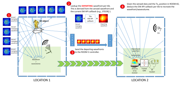
Approach #2 follows a different, more exploratory, research-natured premise. It does not require the extra antenna array pair of approach 1, but introduces SDMs with impinging wavefront sensing capabilities at location 1. Moreover, it targets the remote wavevolume replication, albeit with a latency trade-off. In overview, for the second approach:
-
•
Location 1 is coated with intelligent surfaces that can sense the impinging wavefronts upon them. (The coating can be partial, and this decision is subject to research considerations).
-
•
The impinging wavefront over each surface, along with the corresponding active callback, is sent directly to the SDN controller at location 2. Either SDN controller 1 or 2 can use this information to deduce the wavefront that departs from each intelligent surface at location 1.
-
•
The SDN controller then calculates the SDM callbacks for each surface at location 2 that create the same departing wavefronts as in location 1. (If the two rooms/locations are not identical, the creation can refer to an appropriate distance away from each surface, rather than over the surface itself).
The SDN controller calculations will be sped up via FPGAs to minimize the overall latency.
Further prospects.
iCOPYWAVES ideally replaces the common XR workflow consisting of the discrete steps, i.e., 3D scanning sensory data gathering system synchronization rendering projection, with physical layer-bounded operation operating as
Note that the wide time margin expected to be gained by the iCOPYWAVES approach enables hybrid approaches as well, where:
-
•
Virtually any rendering process can precede projection. This is particularly important, given that RF signals cannot see colors. Therefore, the proposed system provides the 3D geometry of the object, while the XR application rendering can proceed to perform smart texturing and coloring (e.g., from a simple photo taken by a local camera once per few seconds, in a hybrid approach). Moreover, as shown in Fig. 7, the GAN can also learn to color 3D scenes quite effectively and in tandem with the XR-RF imaging process, providing a good range of (even complementary) options, without any camera involved during operation.
-
•
The internal material composition of the 3D object can also be visualized in real-time, since RF signals can penetrate objects. This is a unique capability of the proposed approach, especially useful to medical imaging and industrial material telemetry XR applications [88, 4], compared to existing XR systems.
Finally, remote sites can be flexibly interconnected with over the Internet with some simple, direct sampling-serialization-deserialization of the EM waves. The same approach is employed for carrying complementary data, such as sound and haptic data collected by sensors, cost-effectively and at near-light speed.
Regarding security, we note that the system outlined in Fig. 2 offers capabilities for robust user access control and privacy. Firstly, the outline user authorization process, performed via the SDN controller, ensures the regular degree of security that contemporary information systems can offer. Secondly, the PWE control offers exquisite control over the route taken by the replicated wavefronts (cf. Fig. 2), ensuring that they avoid unauthorized users in real-time [9]. Finally, PWEs have the capability to locally scramble and then descramble a traveling wavefront around a user [89]. This capability can also be used as follows. As shown in Fig. 7 a received wavefront can be viewed as a colored map (using any arbitrary representation process). Therefore, upon a new user entering the system, i) the PWE can be instructed to scramble his received wavefront(s), while ii) the user receives upon entering the system unique descrambling instructions than can restore the intended wavefront colour map to its intended form prior to the GAN processing. In contrast, unauthorized users will receive the same wavefront as “white noise”.
IV Proof-of-concept Evaluation
A proof-of-concept scenario, validating the PWE-enabled XR operation, is simulated in realistic RF ray-tracing software [90], and as shown in Fig. 7.
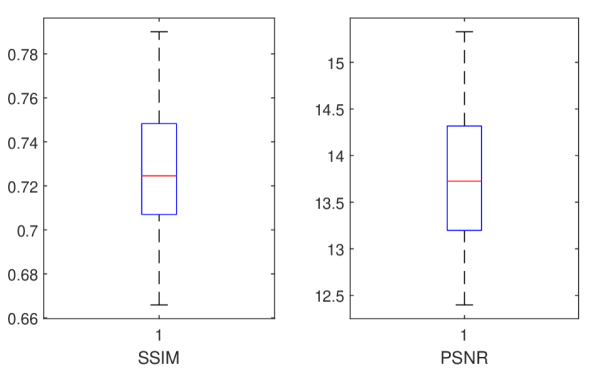
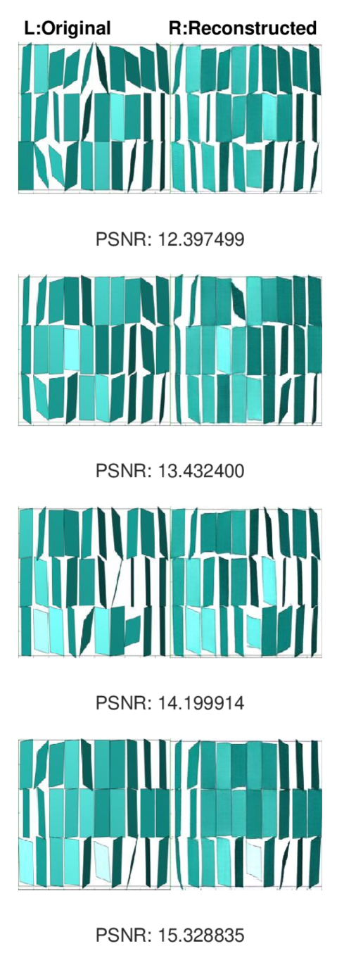
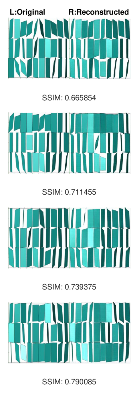
Here, we assume an XR-RF imaging process in a simple room, where the 3D object is a set of randomly rotated rectangular reflectors placed on a wall. Three RF transmitters (yellow horn antennas) emit 5 Hz waves upon the 3D object which scatter around it, and an antenna array with 100 elements gets a corresponding reading. Two standard cameras–(L)eft and (R)ight–take visual snapshots of the 3D object. The process is repeated 1000 times, each time rotating the 3D object randomly, thus, creating a dataset for training a GAN [85], which then translates an RF reading to a visual outcome. Once the training is complete, a second room is added to the layout with all walls covered with metasurfaces (top right). A PWE with two adjacent rooms attempts to copy the wavefront scattered from a random 3D object (arbitrarily rotated rectangular metallic reflectors) from ROOM 1 to ROOM 2. A pre-trained Generative Adversarial Network (GAN) recreates the image of the 3D object. The original wavefront is copied from room 1 to another place in room 2, using a PWE optimization engine [57], and the trained GAN recreates the visual snapshot. We compare the real and reconstructed images via image comparison techniques, and particularly via the Peak SNR (PSNR) and the Structured Similarity Indexing (SSIM) methods [91]. Boxplots of the attained values are given in Fig. 8 per method. Moreover, indicative graphics corresponding to the ranged of quantized comparison outcomes are given in Fig. 9 and 10.
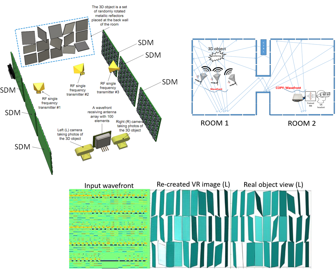
The outcome of this case study already implies that the XR system can efficient provide copying wavefronts/wavevolumes. In particular we observe that:
-
•
The simulated system yields an output close to the ideal one, while also performing artificial coloring of the generated image, also in good agreement with the expectation. Notice that a similar GAN has been used successfully in a medical setting, for translating positron emission tomography (PET) scans to magnetic resonance imaging (MRI) [86].
-
•
The 3D object (randomly rotated rectangular metallic reflectors) constitutes a very challenging case, given that this object has no coherent structure. If the object had coherence (e.g., if the system targeted specific object types, like humans, robotic arms, furniture, etc.), then a “forward correction” could have been performed as a final part of the GAN structure to provide a more accurate output. Another promising approach would be to employ a GNeRF type of GAN [92], which requires multiple RF readings, but i) directly yields the 3D object as output, and ii) offers noise resilience owed to the assembly of the multiple RF readings.
We note that this example does not incorporate a real XR application or an actual SDN controller, while also operating on the premise of ideally performing metasurfaces.
The target functionality is based on the emerging technology of SDM and PWEs developed in recent years [36, 93]. In particular:
-
•
With regards to the metasurface part we assume a unique SDM design and prototype operating at 5 Hz, covering the complete process: from EM analysis, to PCB design, to integration of electronics, and to final prototype assembly [12].
-
•
Additionally, we assume first of its class software family to interact with metasurfaces in a physics-agnostic manner [58]. Firstly, the EM wave manipulation types and their parameters are organized in the form of a software library of callbacks, denoted as the intelligent surface application programming interface (API). This allows computer networking experts to invoke the intelligent surface functionalities without specialized knowledge in physics. Secondly, the translation of such software callbacks into embedded circuit states in real-time was achieved via the offline creation of a lookup database (DB), via extensive measurements and simulations performed during the intelligent surface manufacturing phase. This enabled the real-time operation and re-adaptation of PWEs, while also accounting for unintended effects (e.g., sidelobes), and imprecision stemming from factors such as unintended directions of wave arrivals over SDMs.
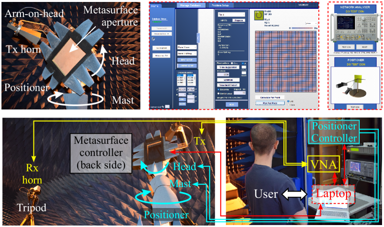
Figure 11: The contributed testbed for realizing an XR copying wavefronts/wavevolumes system. Clockwise, from top left: Close-up photo of a metasurface loaded on an automated positioner and illuminated by a fixed source; screenshots from the developed software that calculates and assigns configurations to a metasurface, and directs the measurement setup.
Finally, a complete implementation can take advantage of a completely automated testbed combining SDM prototypes, dynamically positioned transmitters/receivers, RF measurement devices, and an implementation of the aforementioned software, all controlled via a central computer (shown in Fig. 11-top) [84]. The implemented testbed consists of a bistatic setup inside an anechoic chamber, configured for the measurement of 3D scattering patterns. The testbed employs an automated positioner with a rotating mast and head; a metasurface and a transmitter (Tx) antenna are mounted on the rotating head while a receiving (Rx) antenna is placed on a tripod; the forward transmission of the system is measured with the help of a vector network analyzer (VNA); The entire testbed is controlled by the aforementioned software running on a laptop from the outside of the anechoic chamber; essentially, the software must connect to the VNA and the positioner mast (and head), for the acquisition of a 2D or 3D scattering pattern, and to the SDM for passing different commands.
V Research directions
We proceed to discuss the research challenges towards the implementation of the various components required for iCOPYWAVES system.
Portable hardware for XR-RF Imaging based on machine learning
A crucial and integral part of the complete system is that of the XR headset, which is going to incorporate a technology that ensures real-time visual representation of electromagnetic stimuli from the original room at a minimal energy-consumption footprint.
The purpose is to process the information arriving from the source at a very high speed and the concept is to do so by using a GAN. (Other promising machine learning approaches can be evaluated, posing a separate but secondary challenge). On that topic, FPGA technology has proven to be a highly attractive candidate for such tasks and applications. This is owed to the fact that FPGAs can facilitate parallelized execution, which is suitable for implementing neural networks such as the ones employed within the context of GANs. FPGAs contain hardware resources that can be designed and structured in a multitude of ways in order to implement all sorts of architectures. Hence, FPGAs can also accommodate machine learning inference models, offering the potential for full parallelization at the same-layer neuron execution while accelerating intra-layer execution by pipelining the machine learning computations.
Moreover, FPGAs offer a quantity of hardware resources and this leads to the ability to select the optimum tradeoff between scaling and performance, i.e. given a target throughput, the designer can work towards the dedication of the corresponding hardware resources that will lead to the satisfaction of that particular throughput specification. Overall, the application specifications will pose a set of target specifications such as minimum throughput, maximum area overhead and maximum power consumption, and FPGAs offer the ability to investigate different architectural implementations that yield the best results.
On top of that, it is possible to customize designs to the precise arithmetic required by the neural network and, in fact, design for the particular ones required by the different layers of the network. For instance, it could be that, overall, a given neural network requires INT8 arithmetic to complete. This however, does not mean that the INT8 requirement is posed by all of the network’s layers. It is possible, therefore, with FPGAs to attribute the INT8 arithmetic requirement, to the particular layer that requires it and design the other layers with less demanding requirements such as INT2 and INT4. This has the inherent potential for power saving through hardware minimisation.
Finally, it must be noted that FPGAs come in a wide variety of packages with a highly diverse range of characteristics (e.g., thermal dissipation, power consumption) making them suitable for cloud as well as edge implementations. Hence, they fit seamlessly to the present concept that requires the integration of FPGA-processing into a XR headset. The headset will contain a custom packaging that will host the FPGA, catering for proper thermal management. This board will contain all the necessary electronics that will facilitate the FPGA utilisation such as the conditioning circuitry, which will ensure that the electromagnetic signals received by a MIMO antenna are appropriate for introducing them to the FPGA GAN model.
XR platform for XR-RF imaging and XR merge
This challenge refers to the translation of the outputs of the XR-RF imaging system (GAN output signals) to an immersive XR setting, providing the necessary software platform for developing applications such as teleconferences and education.
The mitigation pathway for this challenge is twofold, one more experimental and one following a more common norm, which also acts as a failover strategy. The first approach is to translate the GAN outputs directly into a video stream that is merged with the XR visual stream, with as little preprocessing as possible. This approach has the potential of a highly simplified operational workflow, resulting into a simplified XR headset hardware in the future as well.
The second approach follows a model-driven approach. Having an array of possible object templates, it uses the GAN outputs to deduce the best matching choice, ensuring that a coherent and artifact-free object is finally rendered. An additional experimental direction is to take into account the XR-RF imaging capability in providing insights about the internal composition and material structure of a remote 3D object, enabling applications such as remote medical imaging or inaccessible material telemetry.
Wireless channel engineering optimization for XR-RF imaging
A major challenge is the microscopic wireless channel modeling, deducing its behavior while copying wavefronts and wavevolumes. This challenge requires a mature electromagnetic design and characterization process as a prerequisite, building upon the previously described challenge, and extending it as follows.
Topology
In far-field imaging, EM waves impinge as plane waves, thus a small difference in distance does not affect significantly the amplitude of echo signals resulting from the distance between each point of the target object and the “radar” being approximately the same [94]. Since passive localization is utilized, it is important to evaluate as many as possible signal routes from the transmitter to each receiver through the monitored object. A distributed or a cascaded architecture can be utilized to cover the space with either transceivers or SDMs to guarantee the tracking of each path. Possible overlaps between coverage areas of the APs can be resolved based on the angle of arrival measurements when multiple antenna elements are available [95]. To control the transmission and to reach beyond possible blockages a number of SDMs has to be deployed in the physical space. In this case, ideally, the whole indoor environment should be covered with SDMs in order to achieve full control and nearly-deterministic sensing, however, with simulations, an ideal number of SDMs can be extracted that accomplishes an acceptable performance in terms of imaging of the indoor environment.
Development of Appropriate Channel Models
The SDM channel modelling accounts for a variety of possible EM/SDM interaction types, including beam steering, beamforming, focusing, modulation, and joint modulation and encoding with the transmitter [96], [9]. Depending on the specific application and wave transformation applied, the path loss and fading models will be extracted via physics-level simulations and theoretically. (Approaches exist for SRE/RIS systems as well, e.g. [97]. For the PWE/SDM case, i.e., the designated approach for iCOPYWAVES, there exist open physics simulation platforms that enable this approach by the scientific community in general [98]). An all-electromagnetic architecture that prescribes PWE-user interaction in the radiative near field should be followed. To this end, it is necessary to rely upon physics-based models for the propagation of EM fields in the proximity of metasurfaces and/or extract circuit models for the problem formulation [65]. Accurate path-loss models for link budget analysis, as well as fading models for sub-wavelength structures, both at the microscopic level, should be developed based on the extension of mathematical physics methods that capture the electromagnetic properties of wave propagation in complex environments [99]. Eventually, the developed models will allow for a quick and scalable study of the PWE control impact on the XR-RF imaging system, without the need for time-consuming precise simulations. Subsequently, the optimized algorithms are integrated for the implementation of the SDN controller and the PWE control algorithms [56].
Dynamic Imaging Controller
In smart XR-RF imaging, RF waves are emitted toward the objects under examination to detect their structure [100]. One or a set of transmitters emit waves upon a 3D scene, and the scattered waves are collected by an array of programmable metasurfaces. Depending on the electromagnetic function applied at these metasurfaces by the image controller, such as beam-steering, diffusion, etc., it is possible to dynamically adjust the captured wavefront which is subsequently mapped to the visual representation of the object through analytical expressions and recent advances in machine learning [96], [9]. The image controller should be able to adjust the scattering diagrams, in order to capture instantly the differences in moving objects. Therefore, it is imperative to explore the combination of these functions that can be applied to the programmable metasurfaces and investigate their effects on detection accuracy.
Quantification of Replication Accuracy
Regarding the impact of the wireless channel on the object detection accuracy, multi-carrier waveforms with advanced peak-to-average power ratio (PAPR) reduction techniques and single-carrier waveforms with advanced modulation techniques are promising research directions, offering reduced PAPR without sacrificing the spectrum efficiency. Moreover, the design of waveforms for narrowband scenarios, characterized by low processing complexity, could be explored to enable power saving. Also, robustness to the restrictions posed by low-cost hardware, e.g., time and frequency offsets, should be examined. For example, on-off modulation is simple to implement and can be useful if the target data and access rate meet the specific scenario requirements. In addition, the geometry of the environment can affect the accuracy of object detection and replication. Complex geometries need high resolution to detect fine details. High resolution can only be obtained with high bandwidth, which would increase the cost of the total system. In this direction, SDMs can assist in creating LoS links increasing the resolution. Finally, predicting accurately the behaviour of the physical assets is another challenge. To address this issue, advanced AI tools can be utilized, which are capable of learning general and complex patterns of the environment by exploiting historical information and exploring future actions and decisions as well. Similarly, AI-optimized constellations and demodulators can assist in decreasing PAPR.
Waveform design
Waveform design can start by implementing known signal forms, such as chirp, and by utilizing reinforcement learning (RL) methods the waveforms can evolve to adapt to each environment [101], [102]. The key challenge in this research direction is that sensing should be performed simultaneously with communication, which facilitates the efficient utilization of so valuable system resources such as bandwidth and power. Waveform design through AI is an area of interest in the research community lately, as AI can design unconventional waveforms that better handle the deteriorations of the channel. In this case, reflectivity and scattering of materials should be showcased [103]. At first, supervised learning could be implemented to evaluate the use of AI for ISAC and then a complete RL framework can be implemented where no prior learning or knowledge of the environment is necessary. The complexity of such a system would be higher, but once a good model of the physical space is created, little changes to the waveforms will be required based only on the mobility and the dynamic changes in the environment.
PWE controller implementation and system component networking
This challenge pertains to the modeling of the PWE at a macroscopic level, designing algorithms for the orchestration of multiple SDMs for wavefront/wavevolume copying, as detailed recently [56]. It integrates the outcomes of the channel engineering challenge, and seeks to create the iCOPYWAVES SDN controller implementation.
Towards this end, this challenge needs to account for the network architecture interconnecting the controller to the SDM in the same or remote locations, from the latency perspective. As intermediate steps, the challenge can be tackled by SDM studying a PWE graph model to abstract the underlying physics at an algorithmic development level. Then, it can proceed to produce resource orchestration algorithms based on this graph model, targeting the creation of wireless propagation paths that perform the wavefront and wavevolume replication from one location to another. Fault tolerance must also be studied, e.g., in terms of system hardware imperfections, system component synchronization irregularities, and user mobility.
In parallel, meeting this challenge also entails taking into account the component integration, i.e., the experimentally verified wireless channel models, as well as the networking infrastructure required to interconnect the PWE system controller to the SDM units. The implementation of the PWE controller culminates this challenge, which completes the infrastructure that iCOPYWAVES requires, apart from the user headset.
Design and manufacturing of SDM units for XR imaging
Regarding the SDM technology required for iCOPYWAVES, challenges concern the design, development and low-level characterization at the physical layer.
This initially entails (a) the design of the SDM that will efficiently perform the advanced wave control required for XR-RF imaging within the PWE; (b) the electronic design of the control circuits and components for the embedded SDM control, and (c) the advanced manufacturing of patterned PCBs as SDM.
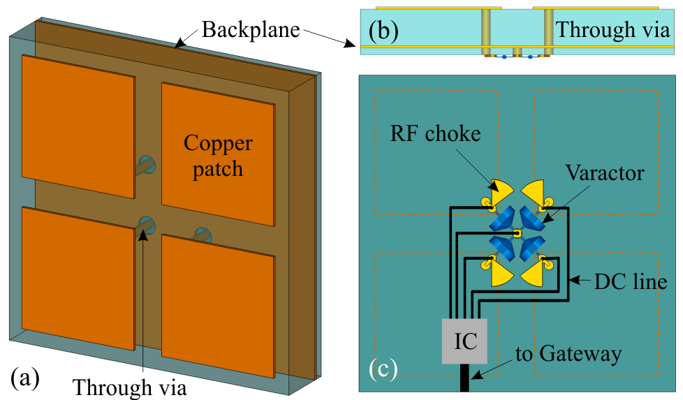
Regarding the electromagnetic design of the SDM, we rely on solid physical conclusions derived in our previous works [26, 12, 51]. More specifically, to be able to perform arbitrary wavefront manipulation with the SDM units, we require local control over the complex surface impedance of the metasurface. This requires individually-controlled unit cells equipped with voltage-driven electronic actuators that control both the reactive and resistive part of the surface impedance. In the GHz regime, such actuators can be implemented with MOSFETs configured as varactor (variable capacitance) and varistor (variable resistor) elements. To be able to control the two linear polarizations separately (and thus additionally perform arbitrary wave, it is also desirable to electrically rotate the “principal axes” of the unit cell; this can be achieved by a composite unit cell design, e.g., based on four patches (see Fig. 12), where individual patches can be connected vertically, horizontally, or diagonally [84].
The fabrication requirements of the proposed SDMs involve the capability of manufacturing high-quality multiple-metallization boards using high-frequency, low-loss specialty substrates. In addition, we need high-aspect ratio through vias and blind vias with uniform metal plating and good electrical conductivity characteristics in order to minimize the resistive loss experienced by the loop currents excited in the unit cell [104]. Finally, the assembly of the controller chips is based on closely-space solder balls to enable the dense packing of unit-cells/controllers. The feasibility of all the above enabling capabilities has been demonstrated in earlier work [105].
Following the electromagnetic/electronic co-design of the PCBs/SDMs and the manufacturing of the designed PCB/SDMs, a formal performance characterization process should be completed. This involves all advanced PCB processing workflows, microfabrication/micropatterning, component assembly on PCB/SDMs according to electromagnetic designs, PCB quality control and lastly, their electrical characterization and wave control performance assessment. Notably, the aforementioned processes are non-standard in the emerging SDM field in general, and need to be further specialized separately for SDM with and without impinging wavefront capabilities.
VI Conclusion
Modern XR faces critical scalability, cost and complexity issues, hindering its wide adoption. These shortcomings stem from the multitude of involved devices that need to cooperate tightly across all layers of the OSI stack. This present paper presented a new approach to XR denoted as iCOPYWAVES, which dictates an end-to-end operation that is bounded at the physical-layer, thereby yielding minimal system latency and architectural simplicity. iCOPYWAVES is based on precise RX imaging (denoted as XR-RF imaging), recent advances in 6G programmable wireless propagation environments, and machine learning. We leverage PWEs to selectively copy RF imaging wavefronts and wavevolumes from one location in space to another, where a machine learning module, accelerated by FPGAs, translates it to visual input for an XR headset. The overarching ambition of iCOPYWAVES is to create a complete platform for: i) creating RF wavefront representations of 3D objects, and ii) manipulating these RF wavefronts with the ease of a “copy-paste” functionality–and no requirements for understanding the complex underlying physics–thereby virtually transferring the original objects to remote locations. The present study detailed the architecture and end-to-end workflow of the iCOPYWAVES approach, and validated its operation via simulations combining ray-tracing and generative adversarial networks. Research challenges towards its implementation and new applications enabled by iCOPYWAVES have been highlighted.
Acknowledgment
This work was partially funded by the European Union’s Horizon 2020 research and innovation programme-project COLLABS, GA EU871518, as well as by the European Research Council (ERC) under grant agreement No. 864228 (AdjustNet), 2020-2025 and the BMBF (Bundesministerium fï¿œr Bildung und Forschung) project, 6G-RIC: 6G Research and Innovation Cluster, 2021-2025.
References
- [1] Y. Siriwardhana, P. Porambage, M. Liyanage, and M. Ylianttila, “A survey on mobile augmented reality with 5g mobile edge computing: Architectures, applications, and technical aspects,” IEEE Communications Surveys & Tutorials, vol. 23, no. 2, pp. 1160–1192, 2021.
- [2] I. F. Akyildiz and H. Guo, “Wireless communication research challenges for extended reality (xr),” ITU Journal Future and Evolving Technologies (ITU J-FET), 2022.
- [3] D. Wang, K. Ohnishi, and W. Xu, “Multimodal haptic display for virtual reality: A survey,” IEEE Transactions on Industrial Electronics, vol. 67, no. 1, pp. 610–623, 2019.
- [4] C. Bermejo and P. Hui, “A survey on haptic technologies for mobile augmented reality,” ACM Computing Surveys (CSUR), vol. 54, no. 9, pp. 1–35, 2021.
- [5] H. B. Wallace, “Analysis of rf imaging applications at frequencies over 100 ghz,” Applied optics, vol. 49, no. 19, pp. E38–E47, 2010.
- [6] R. Murch, C.-Y. Chiu, and S. Shen, “Harnessing ambient rf waves for novel applications,” in 2020 IEEE Asia-Pacific Microwave Conference (APMC). IEEE, 2020, pp. 42–44.
- [7] Y. He, D. Zhang, and Y. Chen, “High-resolution wifi imaging with reconfigurable intelligent surfaces,” arXiv preprint arXiv:2112.00242, 2021.
- [8] B. Zhou, P. Fullagar, and G. Fallon, “Radio frequency tomography trial at mt isa mine,” Exploration geophysics, vol. 29, no. 4, pp. 675–679, 1998.
- [9] C. Liaskos, S. Nie, A. Tsioliaridou, A. Pitsillides, S. Ioannidis, and I. Akyildiz, “A new wireless communication paradigm through software-controlled metasurfaces,” IEEE Communications Magazine, vol. 56, no. 9, pp. 162–169, 2018.
- [10] Q. Wu and R. Zhang, “Towards smart and reconfigurable environment: Intelligent reflecting surface aided wireless network,” IEEE Communications Magazine, vol. 58, no. 1, pp. 106–112, 2019.
- [11] “List of isg ris members and participants,” https://portal.etsi.org/TB-SiteMap/RIS/List-of-ISG-RIS-Members-and-Participants, (Accessed on 06/01/2022).
- [12] O. Tsilipakos, A. C. Tasolamprou, A. Pitilakis, F. Liu, X. Wang, M. S. Mirmoosa, D. C. Tzarouchis, S. Abadal, H. Taghvaee, C. Liaskos et al., “Toward intelligent metasurfaces: the progress from globally tunable metasurfaces to software-defined metasurfaces with an embedded network of controllers,” Advanced Optical Materials, vol. 8, no. 17, p. 2000783, 2020.
- [13] S. Zeng, H. Zhang, B. Di, Y. Tan, Z. Han, H. V. Poor, and L. Song, “Reconfigurable intelligent surfaces in 6g: Reflective, transmissive, or both?” IEEE Communications Letters, vol. 25, no. 6, pp. 2063–2067, 2021.
- [14] N. Kaina, M. Dupré, G. Lerosey, and M. Fink, “Shaping complex microwave fields in reverberating media with binary tunable metasurfaces,” Scientific reports, vol. 4, no. 1, pp. 1–8, 2014.
- [15] P. Del Hougne, M. Fink, and G. Lerosey, “Optimally diverse communication channels in disordered environments with tuned randomness,” Nature Electronics, vol. 2, no. 1, pp. 36–41, 2019.
- [16] L. Zhang, M. Z. Chen, W. Tang, J. Y. Dai, L. Miao, X. Y. Zhou, S. Jin, Q. Cheng, and T. J. Cui, “A wireless communication scheme based on space-and frequency-division multiplexing using digital metasurfaces,” Nature electronics, vol. 4, no. 3, pp. 218–227, 2021.
- [17] L. Dai, B. Wang, M. Wang, X. Yang, J. Tan, S. Bi, S. Xu, F. Yang, Z. Chen, M. D. Renzo, C.-B. Chae, and L. Hanzo, “Reconfigurable intelligent surface-based wireless communications: Antenna design, prototyping, and experimental results,” IEEE Access, vol. 8, pp. 45 913–45 923, 2020.
- [18] J. Zhao, X. Yang, J. Y. Dai, Q. Cheng, X. Li, N. H. Qi, J. C. Ke, G. D. Bai, S. Liu, S. Jin et al., “Programmable time-domain digital-coding metasurface for non-linear harmonic manipulation and new wireless communication systems,” National science review, vol. 6, no. 2, pp. 231–238, 2019.
- [19] H. Zhao, Y. Shuang, M. Wei, T. J. Cui, P. d. Hougne, and L. Li, “Metasurface-assisted massive backscatter wireless communication with commodity wi-fi signals,” Nature communications, vol. 11, no. 1, pp. 1–10, 2020.
- [20] W. Tang, M. Z. Chen, X. Chen, J. Y. Dai, Y. Han, M. Di Renzo, Y. Zeng, S. Jin, Q. Cheng, and T. J. Cui, “Wireless communications with reconfigurable intelligent surface: Path loss modeling and experimental measurement,” IEEE Transactions on Wireless Communications, vol. 20, no. 1, pp. 421–439, 2021.
- [21] W. Tang, J. Y. Dai, M. Z. Chen, K.-K. Wong, X. Li, X. Zhao, S. Jin, Q. Cheng, and T. J. Cui, “Mimo transmission through reconfigurable intelligent surface: System design, analysis, and implementation,” IEEE Journal on Selected Areas in Communications, vol. 38, no. 11, pp. 2683–2699, 2020.
- [22] S. He, H. Yang, Y. Jiang, W. Deng, and W. Zhu, “Recent advances in mems metasurfaces and their applications on tunable lens,” Micromachines, vol. 10, no. 8, p. 505, 2019.
- [23] K. M. Kossifos, L. Petrou, G. Varnava, A. Pitilakis, O. Tsilipakos, F. Liu, P. Karousios, A. C. Tasolamprou, M. Seckel, D. Manessis et al., “Toward the realization of a programmable metasurface absorber enabled by custom integrated circuit technology,” IEEE Access, vol. 8, pp. 92 986–92 998, 2020.
- [24] ——, “Toward the realization of a programmable metasurface absorber enabled by custom integrated circuit technology,” IEEE Access, vol. 8, pp. 92 986–92 998, 2020.
- [25] I. Mehdi, J. Siles, C. Lee, and E. Schlecht, “Thz diode technology: Status, prospects, and applications,” Proceedings of the IEEE, vol. 105, no. 6, pp. 990–1007, 2017.
- [26] F. Liu, O. Tsilipakos, A. Pitilakis, A. Tasolamprou, M. Mirmoosa, N. Kantartzis, D.-H. Kwon, M. Kafesaki, C. Soukoulis, and S. Tretyakov, “Intelligent metasurfaces with continuously tunable local surface impedance for multiple reconfigurable functions,” Physical Review Applied, vol. 11, no. 4, 2019.
- [27] J. He, Z. Xie, W. Sun, X. Wang, Y. Ji, S. Wang, Y. Lin, and Y. Zhang, “Terahertz tunable metasurface lens based on vanadium dioxide phase transition,” Plasmonics, vol. 11, no. 5, pp. 1285–1290, 2016.
- [28] D. Shrekenhamer, W.-C. Chen, and W. Padilla, “Liquid crystal tunable metamaterial absorber,” Physical Review Letters, vol. 110, no. 17, 2013.
- [29] N.-H. Shen, M. Massaouti, M. Gokkavas, J.-M. Manceau, E. Ozbay, M. Kafesaki, T. Koschny, S. Tzortzakis, and C. Soukoulis, “Optically implemented broadband blueshift switch in the terahertz regime,” Physical Review Letters, vol. 106, no. 3, 2011.
- [30] Y. Fan, N.-H. Shen, F. Zhang, Q. Zhao, H. Wu, Q. Fu, Z. Wei, H. Li, and C. Soukoulis, “Graphene plasmonics: A platform for 2d optics,” Advanced Optical Materials, vol. 7, no. 3, 2019.
- [31] A. Tasolamprou, A. Koulouklidis, C. Daskalaki, C. Mavidis, G. Kenanakis, G. Deligeorgis, Z. Viskadourakis, P. Kuzhir, S. Tzortzakis, M. Kafesaki, E. Economou, and C. Soukoulis, “Experimental demonstration of ultrafast thz modulation in a graphene-based thin film absorber through negative photoinduced conductivity,” ACS Photonics, vol. 6, no. 3, pp. 720–727, 2019.
- [32] M. Askari, D. A. Hutchins, P. J. Thomas, L. Astolfi, R. L. Watson, M. Abdi, M. Ricci, S. Laureti, L. Nie, S. Freear et al., “Additive manufacturing of metamaterials: A review,” Additive Manufacturing, p. 101562, 2020.
- [33] M. Bakır, Ş. Dalgaç, E. Ünal, F. Karadağ, M. Demirci, A. S. Köksal, O. Akgöl, and M. Karaaslan, “High sensitive metamaterial sensor for water treatment centres,” Water, Air, & Soil Pollution, vol. 230, no. 12, pp. 1–9, 2019.
- [34] K. P. Zhang, Y. F. Liao, B. Qiu, Y. K. Zheng, L. K. Yu, G. H. He, Q. N. Chen, and D. H. Sun, “3d printed embedded metamaterials,” Small, vol. 17, no. 50, p. 2103262, 2021.
- [35] S. Schmid and J. Suomela, “Exploiting locality in distributed sdn control,” in Proceedings of the second ACM SIGCOMM workshop on Hot topics in software defined networking, 2013, pp. 121–126.
- [36] C. Liaskos, The Internet of Materials. CRC Press, 2020.
- [37] C. Saigre-Tardif, R. Faqiri, H. Zhao, L. Li, and P. del Hougne, “Intelligent meta-imagers: from compressed to learned sensing,” Applied Physics Reviews, vol. 9, no. 1, p. 011314, 2022.
- [38] P. Del Hougne, M. F. Imani, A. V. Diebold, R. Horstmeyer, and D. R. Smith, “Learned integrated sensing pipeline: reconfigurable metasurface transceivers as trainable physical layer in an artificial neural network,” Advanced Science, vol. 7, no. 3, p. 1901913, 2020.
- [39] H.-Y. Li, H.-T. Zhao, M.-L. Wei, H.-X. Ruan, Y. Shuang, T. J. Cui, P. Del Hougne, and L. Li, “Intelligent electromagnetic sensing with learnable data acquisition and processing,” Patterns, vol. 1, no. 1, p. 100006, 2020.
- [40] L. Li, Y. Shuang, Q. Ma, H. Li, H. Zhao, M. Wei, C. Liu, C. Hao, C.-W. Qiu, and T. J. Cui, “Intelligent metasurface imager and recognizer,” Light: science & applications, vol. 8, no. 1, pp. 1–9, 2019.
- [41] T. Sleasman, M. F. Imani, J. N. Gollub, and D. R. Smith, “Dynamic metamaterial aperture for microwave imaging,” Applied Physics Letters, vol. 107, no. 20, p. 204104, 2015.
- [42] Y. B. Li, L. L. Li, B. B. Xu, W. Wu, R. Y. Wu, X. Wan, Q. Cheng, and T. J. Cui, “Transmission-type 2-bit programmable metasurface for single-sensor and single-frequency microwave imaging,” Scientific reports, vol. 6, no. 1, pp. 1–8, 2016.
- [43] E. Bastug, M. Bennis, M. Médard, and M. Debbah, “Toward interconnected virtual reality: Opportunities, challenges, and enablers,” IEEE Communications Magazine, vol. 55, no. 6, pp. 110–117, 2017.
- [44] M. S. Elbamby, C. Perfecto, M. Bennis, and K. Doppler, “Toward low-latency and ultra-reliable virtual reality,” IEEE Network, vol. 32, no. 2, pp. 78–84, 2018.
- [45] M. Abrash, “Latency–the sine qua non of ar and vr,” Blog post, Dec, 2012.
- [46] S. Mangiante, G. Klas, A. Navon, Z. GuanHua, J. Ran, and M. D. Silva, “Vr is on the edge: How to deliver 360 videos in mobile networks,” in Proceedings of the Workshop on Virtual Reality and Augmented Reality Network, 2017, pp. 30–35.
- [47] Z. Li, M. A. Uusitalo, H. Shariatmadari, and B. Singh, “5g urllc: Design challenges and system concepts,” in 2018 15th International Symposium on Wireless Communication Systems (ISWCS). IEEE, 2018, pp. 1–6.
- [48] H. Ren, N. Liu, C. Pan, M. Elkashlan, A. Nallanathan, X. You, and L. Hanzo, “Low-latency c-ran: An next-generation wireless approach,” IEEE Vehicular Technology Magazine, vol. 13, no. 2, pp. 48–56, 2018.
- [49] A. Nasrallah, A. S. Thyagaturu, Z. Alharbi, C. Wang, X. Shao, M. Reisslein, and H. ElBakoury, “Ultra-low latency (ull) networks: The ieee tsn and ietf detnet standards and related 5g ull research,” IEEE Communications Surveys & Tutorials, vol. 21, no. 1, pp. 88–145, 2018.
- [50] H. Taghvaee, S. Abadal, A. Pitilakis, O. Tsilipakos, A. C. Tasolamprou, C. Liaskos, M. Kafesaki, N. V. Kantartzis, A. Cabellos-Aparicio, and E. Alarcon, “Scalability analysis of programmable metasurfaces for beam steering,” IEEE Access, vol. 8, pp. 105 320–105 334, 2020.
- [51] A. Pitilakis, O. Tsilipakos, F. Liu, K. M. Kossifos, A. C. Tasolamprou, D.-H. Kwon, M. S. Mirmoosa, D. Manessis, N. V. Kantartzis, C. Liaskos, M. A. Antoniades, J. Georgiou, C. M. Soukoulis, M. Kafesaki, and S. A. Tretyakov, “A multi-functional reconfigurable metasurface: Electromagnetic design accounting for fabrication aspects,” IEEE Transactions on Antennas and Propagation, vol. 69, no. 3, pp. 1440–1454, 2021.
- [52] Z. Viskadourakis, E. Tamiolakis, O. Tsilipakos, A. C. Tasolamprou, E. N. Economou, and G. Kenanakis, “3d-printed metasurface units for potential energy harvesting applications at the 2.4 ghz frequency band,” Crystals, vol. 11, no. 9, 2021.
- [53] T. Cui, M. Qi, X. Wan, J. Zhao, Q. Cheng, K.-T. Lee, J. Lee, S. Seo, L. Guo, Z. Zhang, Z. You, and D. Chu, “Coding metamaterials, digital metamaterials and programmable metamaterials,” Light: Science and Applications, vol. 3, no. 10, 2014.
- [54] S. Glybovski, S. Tretyakov, P. Belov, Y. Kivshar, and C. Simovski, “Metasurfaces: From microwaves to visible,” Physics Reports, vol. 634, pp. 1–72, 2016.
- [55] S. Dash, C. Psomas, I. Krikidis, I. F. Akyildiz, and A. Pitsillides, “Active control of thz waves in wireless environments using graphene-based ris,” IEEE Transactions on Antennas and Propagation, 2022.
- [56] C. Liaskos, L. Mamatas, A. Pourdamghani, A. Tsioliaridou, S. Ioannidis, A. Pitsillides, S. Schmid, and I. F. Akyildiz, “Software-defined reconfigurable intelligent surfaces: From theory to end-to-end implementation,” Proceedings of the IEEE, 2022.
- [57] C. Liaskos, A. Tsioliaridou, S. Nie, A. Pitsillides, S. Ioannidis, and I. F. Akyildiz, “On the network-layer modeling and configuration of programmable wireless environments,” IEEE/ACM Transactions on Networking, vol. 27, no. 4, pp. 1696–1713, 2019.
- [58] C. Liaskos, A. Tsioliaridou, S. Ioannidis, A. Pitsillides, and I. F. Akyildiz, “Next generation connected materials for intelligent energy propagation in multiphysics systems,” IEEE Communications Magazine, vol. 59, no. 8, pp. 100–106, 2021.
- [59] M. D. Renzo, M. Debbah, D.-T. Phan-Huy, A. Zappone, M.-S. Alouini, C. Yuen, V. Sciancalepore, G. C. Alexandropoulos, J. Hoydis, H. Gacanin et al., “Smart radio environments empowered by reconfigurable ai meta-surfaces: An idea whose time has come,” EURASIP Journal on Wireless Communications and Networking, vol. 2019, no. 1, pp. 1–20, 2019.
- [60] X. Qian and M. Di Renzo, “Mutual coupling and unit cell aware optimization for reconfigurable intelligent surfaces,” IEEE Wireless Communications Letters, vol. 10, no. 6, pp. 1183–1187, 2021.
- [61] L. Subrt and P. Pechac, “Intelligent walls as autonomous parts of smart indoor environments,” IET communications, vol. 6, no. 8, pp. 1004–1010, 2012.
- [62] X. Tan, Z. Sun, D. Koutsonikolas, and J. M. Jornet, “Enabling indoor mobile millimeter-wave networks based on smart reflect-arrays,” in IEEE INFOCOM 2018-IEEE Conference on Computer Communications. IEEE, 2018, pp. 270–278.
- [63] S. Han and K. G. Shin, “Enhancing wireless performance using reflectors,” in IEEE INFOCOM 2017-IEEE Conference on Computer Communications. IEEE, 2017, pp. 1–9.
- [64] A. Welkie, L. Shangguan, J. Gummeson, W. Hu, and K. Jamieson, “Programmable radio environments for smart spaces,” in Proceedings of the 16th ACM Workshop on Hot Topics in Networks, 2017, pp. 36–42.
- [65] M. Di Renzo, F. Habibi Danufane, X. Xi, J. de Rosny, and S. Tretyakov, “Analytical Modeling of the Path-Loss for Reconfigurable Intelligent Surfaces-Anomalous Mirror or Scatterer?” in 2020 IEEE SPAWC, 2020, pp. 1–5.
- [66] C. Liaskos, A. Tsioliaridou, S. Ioannidis, A. Pitsillides, and I. F. Akyildiz, “Next generation connected materials for intelligent energy propagation in multiphysics systems,” IEEE Communications Magazine, vol. 59, no. 8, pp. 100–106, 2021.
- [67] I. Alamzadeh, G. Alexandropoulos, N. Shlezinger, and M. Imani, “A reconfigurable intelligent surface with integrated sensing capability,” Scientific Reports, vol. 11, no. 1, 2021.
- [68] C. Huang, S. Hu, G. C. Alexandropoulos, A. Zappone, C. Yuen, R. Zhang, M. Di Renzo, and M. Debbah, “Holographic mimo surfaces for 6g wireless networks: Opportunities, challenges, and trends,” IEEE Wireless Communications, vol. 27, no. 5, pp. 118–125, 2020.
- [69] J. Hunt, T. Driscoll, A. Mrozack, G. Lipworth, M. Reynolds, D. Brady, and D. Smith, “Metamaterial apertures for computational imaging,” Science, vol. 339, no. 6117, pp. 310–313, 2013.
- [70] J. Hunt, J. Gollub, T. Driscoll, G. Lipworth, A. Mrozack, M. S. Reynolds, D. J. Brady, and D. R. Smith, “Metamaterial microwave holographic imaging system,” J. Opt. Soc. Am. A, vol. 31, no. 10, pp. 2109–2119, Oct 2014.
- [71] W. Wan, J. Gao, and X. Yang, “Metasurface holograms for holographic imaging,” Advanced Optical Materials, vol. 5, no. 21, 2017.
- [72] M. F. Imani, T. Sleasman, and D. R. Smith, “Two-dimensional dynamic metasurface apertures for computational microwave imaging,” IEEE Antennas and Wireless Propagation Letters, vol. 17, no. 12, pp. 2299–2303, 2018.
- [73] A. Darvazehban, S. Ahdi Rezaeieh, A. Zamani, and A. M. Abbosh, “Pattern reconfigurable metasurface antenna for electromagnetic torso imaging,” IEEE Transactions on Antennas and Propagation, vol. 67, no. 8, pp. 5453–5462, 2019.
- [74] S. Hosseininejad, K. Rouhi, M. Neshat, R. Faraji-Dana, A. Cabellos-Aparicio, S. Abadal, and E. Alarcon, “Reprogrammable graphene-based metasurface mirror with adaptive focal point for thz imaging,” Scientific Reports, vol. 9, no. 1, 2019.
- [75] A. Diebold, M. Imani, T. Sleasmanand, and D. Smith, “Phaseless coherent and incoherent microwave ghost imaging with dynamic metasurface apertures,” Optica, vol. 5, no. 12, pp. 1529–1541, 2018.
- [76] B. Davis, D. Marks, T. Ralston, P. Carney, and S. Boppart, “Interferometric synthetic aperture microscopy: Computed imaging for scanned coherent microscopy,” Sensors, vol. 8, no. 6, pp. 3903–3931, Jun. 2008. [Online]. Available: https://doi.org/10.3390/s8063903
- [77] M. Del Hougne, S. Gigan, and P. Del Hougne, “Deeply subwavelength localization with reverberation-coded aperture,” Physical Review Letters, vol. 127, no. 4, p. 043903, 2021.
- [78] Y. Gao, Y. Fan, Y. Wang, W. Yang, Q. Song, and S. Xiao, “Nonlinear holographic all-dielectric metasurfaces,” Nano letters, vol. 18, no. 12, pp. 8054–8061, 2018.
- [79] B. Zheng and R. Zhang, “Intelligent reflecting surface-enhanced ofdm: Channel estimation and reflection optimization,” IEEE Wireless Communications Letters, vol. 9, no. 4, pp. 518–522, 2019.
- [80] M.-M. Zhao, Q. Wu, M.-J. Zhao, and R. Zhang, “Intelligent reflecting surface enhanced wireless network: Two-timescale beamforming optimization,” IEEE Transactions on Wireless Communications, 2020.
- [81] Q. Wu and R. Zhang, “Joint active and passive beamforming optimization for intelligent reflecting surface assisted swipt under qos constraints,” IEEE Journal on Selected Areas in Communications, vol. 38, no. 8, pp. 1735–1748, 2020.
- [82] S. Abeywickrama, R. Zhang, Q. Wu, and C. Yuen, “Intelligent reflecting surface: Practical phase shift model and beamforming optimization,” IEEE Transactions on Communications, vol. 68, no. 9, pp. 5849–5863, 2020.
- [83] C. Liaskos, S. Nie, A. Tsioliaridou, A. Pitsillides, S. Ioannidis, and I. Akyildiz, “End-to-end wireless path deployment with intelligent surfaces using interpretable neural networks,” IEEE Transactions on Communications, 2020.
- [84] C. Liaskos, A. Tsioliaridou, S. Ioannidis, A. Pitsillides, and I. F. Akyildiz, “The internet of metamaterial things and their software enablers,” ITU Journal of Future and Emerging Technologies, vol. 1, no. 1, pp. 55–77, 2020.
- [85] L. Jiao, C. Hu, L. Huo, and P. Tang, “Guided-pix2pix: End-to-end inference and refinement network for image dehazing,” IEEE Journal of Selected Topics in Applied Earth Observations and Remote Sensing, vol. 14, pp. 3052–3069, 2021.
- [86] M. M. Jung, B. van den Berg, E. Postma, and W. Huijbers, “Inferring pet from mri with pix2pix,” in Benelux Conference on Artificial Intelligence, vol. 9, 2018.
- [87] Y. Tang, W. Shieh, X. Yi, and R. Evans, “Optimum design for rf-to-optical up-converter in coherent optical ofdm systems,” IEEE Photonics Technology Letters, vol. 19, no. 7, pp. 483–485, 2007.
- [88] L. F. de Souza Cardoso, F. C. M. Q. Mariano, and E. R. Zorzal, “A survey of industrial augmented reality,” Computers & Industrial Engineering, vol. 139, p. 106159, 2020.
- [89] C. Liaskos, S. Nie, A. Tsioliaridou, A. Pitsillides, S. Ioannidis, and I. Akyildiz, “A novel communication paradigm for high capacity and security via programmable indoor wireless environments in next generation wireless systems,” Ad Hoc Networks, vol. 87, pp. 1–16, 2019.
- [90] P. Mededjovic, M. Veletic, and Z. Blagojevic, “Wireless insite software verification via analysis and comparison of simulation and measurement results,” in 2012 Proceedings of the 35th International Convention MIPRO. IEEE, 2012, pp. 776–781.
- [91] U. Sara, M. Akter, and M. S. Uddin, “Image quality assessment through FSIM, SSIM, MSE and PSNR—A comparative study,” J. Comput. Commun., vol. 07, no. 03, pp. 8–18, 2019.
- [92] Q. Meng, A. Chen, H. Luo, M. Wu, H. Su, L. Xu, X. He, and J. Yu, “Gnerf: Gan-based neural radiance field without posed camera,” in Proceedings of the IEEE/CVF International Conference on Computer Vision, 2021, pp. 6351–6361.
- [93] F. (Coord.), “Project visorsurf: A hypervisor for metasurface functionalities,” in EU FETOPEN RIA - H2020, Dec–2020.
- [94] S. Buzzi, E. Grossi, M. Lops, and L. Venturino, “Radar Target Detection Aided by Reconfigurable Intelligent Surfaces,” IEEE Signal Process. Lett., vol. 28, pp. 1315–1319, 2021.
- [95] D. Tyrovolas, S. A. Tegos, E. C. Dimitriadou-Panidou, P. D. Diamantoulakis, C. K. Liaskos and G. K. Karagiannidis, ”Performance Analysis of Cascaded Reconfigurable Intelligent Surface Networks,” in IEEE Wireless Communications Letters, vol. 11, no. 9, pp. 1855-1859, Sept. 2022,
- [96] S. A. Tegos, D. Tyrovolas, P. D. Diamantoulakis, C. K. Liaskos, and G. K. Karagiannidis, “On the Distribution of the Sum of Double-Nakagami-m Random Vectors and Application in Randomly Reconfigurable Surfaces,” IEEE Trans. Veh. Technol., vol. 71, no. 7, pp. 7297-7307, July 2022
- [97] R. Faqiri, C. Saigre-Tardif, G. C. Alexandropoulos, N. Shlezinger, M. F. Imani, and P. del Hougne, “Physfad: Physics-based end-to-end channel modeling of ris-parametrized environments with adjustable fading,” IEEE Transactions on Wireless Communications, pp. 1–1, 2022.
- [98] A. Papadopoulos, A. Lalas, K. Votis, D. Tyrovolas, G. Karagiannidis, S. Ioannidis, and C. Liaskos, “An open platform for simulating the physical layer of 6g communication systems with multiple intelligent surfaces,” in IEEE CNSM’22.
- [99] F. H. Danufane, M. D. Renzo, J. de Rosny, and S. Tretyakov, “On the Path-Loss of Reconfigurable Intelligent Surfaces: An Approach Based on Green’s Theorem Applied to Vector Fields,” IEEE Trans. Commun., vol. 69, no. 8, pp. 5573–5592, 2021.
- [100] S. Depatla, C. R. Karanam, and Y. Mostofi, “Robotic Through-Wall Imaging: Radio-Frequency Imaging Possibilities with Unmanned Vehicles,” IEEE Antennas Propag Mag, vol. 59, no. 5, pp. 47–60, 2017.
- [101] F. Liu, L. Zhou, C. Masouros, A. Li, W. Luo, and A. Petropulu, “Toward Dual-functional Radar-Communication Systems: Optimal Waveform Design,” IEEE Trans. Signal Process., vol. 66, no. 16, pp. 4264–4279, 2018.
- [102] G. E. Smith and T. J. Reininger, “Reinforcement Learning For Waveform Design,” in 2021 IEEE RadarConf21, 2021, pp. 1–6.
- [103] C. Liaskos, A. Tsioliaridou, A. Pitsillides, I. F. Akyildiz, N. V. Kantartzis, A. X. Lalas, X. Dimitropoulos, S. Ioannidis, M. Kafesaki, and C. Soukoulis, “Design and Development of Software Defined Metamaterials for Nanonetworks,” IEEE Circuits Syst. Mag., vol. 15, no. 4, pp. 12–25, 2015.
- [104] A. Pitilakis, M. Seckel, A. Tasolamprou, F. Liu, A. Deltsidis, D. Manessis, A. Ostmann, N. Kantartzis, C. Liaskos, C. Soukoulis et al., “Multi-functional metasurface architecture for amplitude, polarization and wavefront control,” arXiv preprint arXiv:2204.03962, 2022.
- [105] D. Manessis, M. Seckel, L. Fu, O. Tsilipakos, A. Pitilakis, A. Tasolamprou, K. Kossifos, G. Varnava, C. Liaskos, M. Kafesaki et al., “Manufacturing of high frequency substrates as software programmable metasurfaces on pcbs with integrated controller nodes,” in 2020 IEEE 8th Electronics System-Integration Technology Conference (ESTC). IEEE, 2020, pp. 1–7.