Terrace effects in grazing-incidence fast atom diffraction from a LiF(001) surface
Abstract
The effect produced by surface defects on grazing-incidence fast atom diffraction (GIFAD) patterns is studied by considering the presence of terraces in a LiF(001) sample. For helium atoms impinging along the direction of the LiF surface, we analyze the influence of a monolayer terrace with its edge oriented parallel or perpendicular to the axial channel. We found that the presence of an outward transverse step introduces a diffuse background above the Laue circle, which displays additional peaked structures. For inward transverse steps, instead, such a background is placed below the Laue circle, showing a much weaker intensity. On the other hand, parallel steps give rise to asymmetric angular distributions, which are completely confined to the Laue circle. Therefore, these theoretical results suggest that GIFAD might be used to characterize terrace defects.
I Introduction
Grazing-incidence fast atom diffraction (GIFAD) is an exceptionally sensitive technique of surface analysis, which provides detailed information of the electronic and morphological features of the surface Winter2011 ; Debiossac2017 . During the 15 years since its first observation Schuller2007 ; Rousseau2007 , the GIFAD method has been successfully applied to study the topmost atomic layer of a wide variety of materials, ranging from insulators Schuller2012 , semiconductors Debiossac2014 and metals Rios2013 to adsorbate-covered metal surfaces Schuller2009b , ultrathin films Seifert2010 , organic-metal interfaces Seifert2013 ; Momeni2018 , and graphene layers Zugarramurdi2015 . But in all cases, the use of well-ordered crystal targets was considered an important prerequisite for the observation of interference patterns Winter2011 .
In GIFAD the periodic ordering requirement of the crystal sample is particularly crucial along the axial direction because projectiles probe long distances of the surface along the incidence channel, about some hundred Å. Hence, careful crystal manufacture and surface preparation represent central issues in GIFAD experiments. Nevertheless, even under extremely good cleanness conditions, real crystals have step defects that could affect the interference patterns Farias2002 . In the case of alkali-halide crystals, such as NaCl, KBr, and LiF, high resolution images provided by atomic force microscopy commonly reveal the presence of terraces or steps on the topmost layer Meyer1988 ; Prohaska1994 , which are unavoidable in the preparation process of the sample Vidal2019 .
In this paper we address how the existence of terraces in a LiF(001) surface might affect the diffraction patterns produced by grazing impact of fast He atoms. The He/LiF(001) system has been extensively studied with GIFAD, being currently considered as a prototype for this phenomenon. However, all the theoretical descriptions assume an ideal perfect crystal surface diaz2022 , whereas defect contributions were only qualitatively discussed Winter2011 ; Debiossac2021 .
The influence of surface terraces on GIFAD patterns is investigated here by considering simple crystallographic geometries: a unique up- or down- step, oriented perpendicular or parallel to the incidence channel. Different step locations, relative to the focus position of the atomic beam, are analyzed. Although such geometries represent an oversimplified description of actual LiF surfaces, they will allow us to shed light on the expected contribution of more complex step defects.
Our study is based on the use of the surface initial value representation (SIVR) approximation Gravielle2014 ; Gravielle2015 , which is a semiquantum method that offers a satisfactory description of GIFAD in terms of classical projectile trajectories. The projectile-surface interaction, which is a key ingredient in all GIFAD simulations, is described by means of the pairwise additive (PA) potential of Refs. Miraglia2017 ; Gravielle2019 . This PA potential is built as a sum of binary interatomic potentials that represent the interaction of the atomic projectile with individual ionic centers in the crystal, incorporating nonlocal contributions of the electron density, along with the effect of the Madelung potential. Concerning our theoretical model, it should be mentioned that the combination of the SIVR approach with this PA potential has already shown to provide GIFAD patterns in very good agreement with available experimental data for the He/LiF(001) system under different incidence conditions Gravielle2014 ; Gravielle2015 ; Frisco2018 . Furthermore, the use of PA models to represent the surface interaction makes it possible to modify the crystallographic structure to include defects, such as terraces, without an additional computational cost, which represents an important advantage in comparison with ab initio calculations, like the ones based on density functional theory.
The article is organized as follows. The theoretical model is summarized in Sec. II, while results for step defects transverse and parallel to the axial direction are presented and discussed in Secs. III. A and III.B respectively. In Sec. IV we outline our conclusions. Atomic units (a.u.) are used unless otherwise stated.
II Theoretical model
Within the SIVR approximation, the effective transition amplitude for elastic atom-surface scattering reads Frisco2018 ; Gravielle2018
| (1) | |||||
where
| (2) | |||||
is the partial amplitude corresponding to the classical projectile trajectory , which starts at the initial time in the position with momentum . The functions and describe the spatial and momentum profiles, respectively, of the incident projectile wave-packet, while the vector denotes the initial position of the wave-packet center. In Eq. (2), is the Maslov factor (a determinant), represents the projectile-surface interaction along the projectile path, and is the projectile momentum transfer, with ( ) being the initial (final) projectile momentum and . The SIVR phase at time reads Gravielle2014
| (3) |
where is the projectile mass and is the classical projectile momentum.
In this work, the projectile-surface potential is evaluated with the PA model of Refs. Miraglia2017 ; Gravielle2019 . It is expressed as
| (4) |
where describes the short-range binary interaction between the projectile and the crystal ion placed at the Bravais lattice site , as a function of the relative vector , and denotes the projectile polarization term, which describes the long-range projectile-surface interaction due to the rearrangement of the electron density of the atomic projectile.
The binary potentials are expressed in terms of the unperturbed electron densities of the projectile and the ionic sites, incorporating not only non-local contributions of these electron densities, but also the Madelung contribution, i.e., the effect of the ionic crystal lattice on the electron density around each individual ionic site. In turn, the potential depends on the surface electric field at the position of the atomic projectile, reading
| (5) |
where is the dipole polarizability of the projectile ( a.u. for He atoms) and is the electric field produced by the asymptotic charge of the crystal ion placed at . In Eqs. (4) and (5) the summation on covers all the occupied lattice sites of the crystal sample, taking into consideration the presence of flat terraces, as well as the rumpling of the topmost atomic layer of each terrace, while the sub-index in and was included to distinguish the the two different ions of the crystallographic basis.
From Eq. (1), the differential probability of scattering in the direction of the solid angle , with () being the final polar (azimuthal) angle measured with respect to the surface (axial channel), can be obtained as:
| (6) |
where the integral on covers an area equal to a reduced unit cell of the crystal surface. This integration, associated with the spot-beam effect Frisco2018 , takes into account that it is experimentally impossible to control the focus position of the atomic beam with nanoscale precision. Details about the SIVR method can be found in Refs. Gravielle2014 ; Gravielle2015 ; Frisco2018 ; Gravielle2018 .
III Results
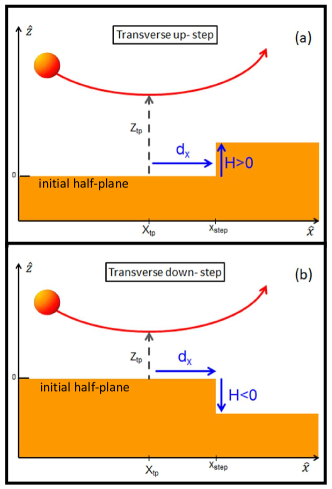
With the aim of studying the effect produced by the presence of terraces in alkali-halide crystal surfaces, we evaluated diffraction patterns for 4He atoms scattered off LiF(001) along the direction considering a crystal sample with one step of height oriented perpendicular or parallel to the incidence channel. The height of the step was assumed to be equal to the distance between layers, that is, , where is the lattice parameter ( Å for LiF) and the sign indicates an outward () or inward () terrace parallel to the surface plane (see Fig. 1). Notice that for alkali-halide surfaces, atomically flat terraces with sizes ranging from to Å can be observed under the usual cleanness conditions Prohaska1994 . But the heights of these terraces are also variable and they can be higher than the monolayer height Meyer1988 .
The terrace was simulated by adding or removing a monolayer (according to the sign of ) in the topmost half-plane of the crystal sample, as depicted in Fig. 1. The topmost atomic layer of the terrace includes the rumpling, that is, the different relaxation of the outermost F- and Li+ ions with respect to the unreconstructed plane Miraglia2017 . However, our simplified step model neglects the reconstruction effects at the edge of the terrace, describing the crystal defect as a sharp step. Even though such an ideal cutting of the crystal terrace represents a rough description of real surface defects, this assumption can be consider as a zero-order approach to study the influence of step defects in GIFAD. Moreover, recent topographic images of other alkali-halide crystal - KBr - show sharp profiles of the monatomic steps Ito2016 .
In this article, we chosen a fixed impact energy, keV, for which experimental GIFAD distributions are available Schuller2009c . Two normal incidence energies ( denotes the glancing incidence angle) are analyzed - and eV - which correspond respectively to low and intermediate values for He/LiF GIFAD Schuller2009 . Notice that for the latter normal energy, the experimental projectile distribution reported in Ref. Schuller2009c was adequately described with our theoretical method without taking into account the presence of crystal defects Frisco2018 . Then, such a good theory-experiment agreement suggests that typical GIFAD experiments are carried out on large flat terraces, being unaffected by step defects Debiossac2021 .
For different configurations and relative positions of the monolayer step, two-dimensional projectile distributions, as a function of the final polar and azimuthal angles, were calculated within the SIVR approach, as given by Eq. (6). In the calculation of [Eq. (1)], the spatial and momentum profiles of the incident wave packet were determined as given in Refs. Gravielle2015 ; Gravielle2018 by considering a collimating scheme formed by a rectangular slit of area mm2 (the latter length in the transverse direction) placed at cm from the surface, with an angular beam dispersion of deg. From these collimating parameters, which are in agreement with current experimental setups Bocan2020 , we derived the transverse coherence lengths in the directions perpendicular () and parallel () to the incidence channel Gravielle2015 ; Gravielle2018 - Å and () Å for () eV - which verify the relation . It reinforces the fact that under grazing incidence, helium projectiles probe much longer distances along the axial channel than in the perpendicular direction, making GIFAD patterns more sensitive to transverse steps, oriented perpendicular to the channel, than to those oriented in the parallel direction.
III.1 Effects due to a transverse terrace
In this subsection, we consider a LiF(001) surface with a monolayer step oriented perpendicular to the axial direction. To investigate the influence of the position of the border of the terrace on the diffraction patterns, we determine the relative position of the transverse step by means of the distance between the edge of the terrace and the mean focus point of the incident beam, that is,
| (7) |
where is the step position along the incidence channel () and denotes the mean position along of the focus point of the helium beam. The value of is defined as the average of the - positions corresponding to the turning points of projectile trajectories specularly reflected from a perfect surface (see Fig. 1). For an ideal LiF(001) crystal, these trajectories run on the flat regions of the projectile-surface potential, i.e., along the F- or Li+ rows.
Using the relative step position defined by Eq. (7), positive distances indicate that He projectiles should reach the turning point before being affected by the step in the outgoing path, while negative values are associated with steps affecting the incoming path of the incident atoms. Clearly, this is only an overall description of the scattering process in the presence of surface terraces because depending on the incidence conditions and the value, the turning points of scattered projectiles could be modified by the strong change in the surface potential introduced by the presence of the outward or inward step.
We start analyzing projectile distributions for the higher normal energy - eV - for which terrace effects are expected to be more important. For this normal energy, corresponding to the incidence angle , simulated diffraction patterns respectively derived from a perfect LiF(001) surface and from a surface with an upward step placed at a distance Å are compared in Fig. 2. Taking into account that large terraces are usually present in the LiF samples used in GIFAD experiments Debiossac2021 , this distance corresponds to a step position relatively close to the beam focus point.
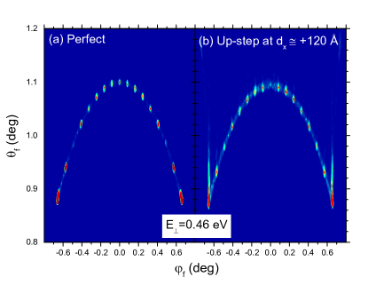
Both panels of Fig. 2 present similar interference structures, with equally - spaced Bragg maxima lying on a thin annulus associated with the Laue circle Rousseau2007 ; Schuller2008 , which is defined by . However, as a consequence of the presence of the upward step, the angular distribution of Fig. 2 (b) shows outermost peaks noticeably extended towards larger polar angles, along with different relative intensities of the inner peaks, in comparison with those for a perfect surface (Fig. 2 (a)). Regarding this latter effect, notice that the intensities of the Bragg maxima are modulated by the intra-channel interference, associated with the profile of the surface potential across the axial direction Schuller2008 ; Gravielle2014 , which suffers a local change at the edge of the terrace. Instead, the positions of the Bragg peaks are determined by the inter-channel interference, which depends on the spacing between equivalent parallel channels Schuller2008 ; Gravielle2014 , a parameter that is not altered by the transverse step.
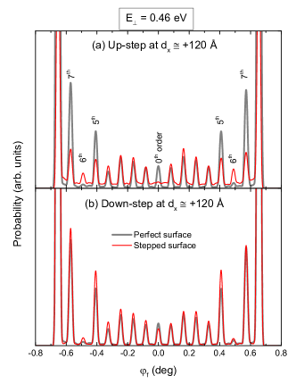
To thoroughly analyze the step effect on Bragg-peak intensities, in Fig. 3 (a) we compare the azimuthally projected distributions corresponding to the two panels of Fig. 2, obtained by integrating Eq. (6) over a reduced area on the Laue circle Debiossac2016 . In Fig. 3 (a) we observe that the presence of the transverse up-step introduces an almost constant background in the azimuthal spectrum. Furthermore, the distortion of the surface potential caused by the outward step strongly affects the peak intensities, markedly reducing the relative intensity of the maxima of orders and , as well as that of the central peak ( order) whose intensity becomes much lower than those of the adjacent maxima, in contrast to what is observed for a perfect surface. Also, the intensity of the outermost maxima (not shown in Fig. 3 (a) ) is lowered as a result of the surface defect, whereas the intensity of - order maxima is raised, making these latter peaks visible.
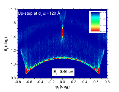
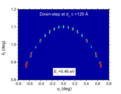
At this point, it is important to recall that typical GIFAD patterns for perfect crystal surfaces are essentially determined by the surface potential averaged along the axial direction Zugarramurdi2012 ; Muzas2016 . But the presence of a transverse step breaks the translation invariance associated with this averaged surface potential, altering the effective slope of the reflection plane around the edge of the terrace. This fact is evidenced in Fig. 4, where we have extended the range of Fig. 2 (b), lowering also the intensity scale by one order of magnitude to show the terrace effects. The projectile distribution of Fig. 4 presents a diffuse background for , with additional peaks at the central and outermost azimuthal angles. In this case, a large proportion of the scattered projectiles ( ) are deflected above the Laue circle due to the steep increase of the surface potential at the step position, while about of the incident projectiles penetrates in the terrace bulk.
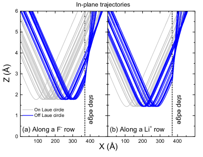
Since the most remarkable feature of the projectile distribution of Fig. 4 is the central peak above the Laue circle, which is placed at , in Fig. 5 we show a sample of random projectile paths that contribute to the central region of this angular distribution. Such trajectories are confined to the scattering plane (i.e., in-plane trajectories), initially running along the F- or Li+ rows of the topmost layer in the initial half-plane (note that F- or Li+ rows switch at the terrace), as respectively shown in Figs. 5 (a) and 5 (b). In both panels, the wide - spread of the classical turning points is associated with the large value. Hence, projectile paths with turning points far away from the step end on the Laue circle, without being affected by the presence of the upward terrace. But those trajectories with turning points placed at distances () Å in Fig. 5 (a) (Fig. 5 (b)), are deflected with a final polar angle due to the change in the surface potential, which abruptly becomes repulsive at the step. We stress that in Fig. 4, the on-Laue interference maxima, as well as the intense outermost peaks above the Laue circle, are produced by quantum interference among partial transition amplitudes corresponding to different projectile paths, that is, they cannot be explained as points of accumulation of trajectories. However, the central maximum above the Laue circle has a classical origin, also being observed in the classical projectile distribution.
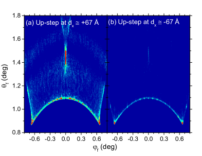
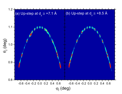
A similar central off-Laue maximum, associated with the presence of the transverse terrace, can be seen in Fig. 6 (a) for Å, a step position even closer to . But in this case, since the atomic beam is almost focused on the step region, Bragg peaks start to wash out, whereas the central peak above the Laue circle is clearly visible without increasing the sensitivity of the intensity scale. The same up-step effects are also observed in the projectile distribution of Fig. 6 (b) corresponding to an upward step placed in front of the focus point, at Å. Nevertheless, the intensity of the background and the off-Laue peaks markedly decreases as the projectile trajectories meet the terrace edge in their incoming paths.
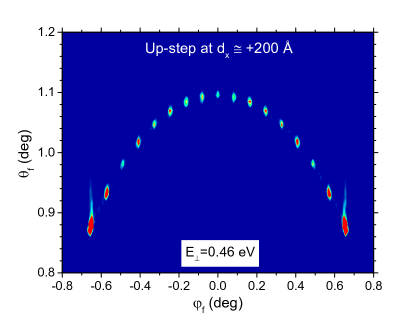
As expected, the step effects gradually disappear as the distance increases. The projectile distribution for an upward step placed at Å, plotted in Fig. 7, looks similar to that for a perfect crystal surface (Fig. 2 (a)), without any signature of the terrace effects, except for the polar elongation of the outermost peaks with respect to those derived from a perfect surface. Under these incidence conditions, most helium projectiles () hit the detector plane with , while only a very small fraction () penetrates into the bulk at the step, indicating that the projectile distribution tends to the one corresponding to a perfect LiF surface.
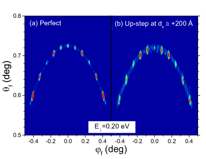
The distance for which unperturbed GIFAD patterns can be obtained depends on the normal energy. When decreases, so does, grazing projectiles probe longer distances along the axial direction, being affected by transverse upward steps placed at longer distances . This fact can be observed in Fig. 8 (b), where the projectile distribution for eV ( ), produced by a crystallographic configuration similar to that of Fig. 7, shows noticeable changes in the relative peak intensities, with respect to those derived by considering a perfect crystal surface, displayed in Fig. 8 (a).
Finally, we analyze the influence of a transverse down-step, as depicted in Fig. 1 (b). In Fig. 9, we plot the angular distribution for eV derived by considering an inward step placed at Å. In contrast to the up-step effects shown in Fig. 2 (b), the presence of the down step does not affect the on-Laue distribution, which is similar to that for a perfect surface (Fig. 2 (a)). This feature can be quantitative confirmed by comparing the corresponding azimuthally projected spectra, which are quite alike, as observed in Fig. 3 (b). In the case of Fig. 9, however, although approximately of the trajectories are scattered from the LiF surface with , there are trajectories whose outgoing paths are distorted by the decrease of the potential at the edge of the terrace, being deflected below the Laue circle. It gives rise to a diffuse background below the Laue circle, whose intensity is several orders of magnitude lower than those of Bragg peaks.
III.2 Effects due to a parallel terrace
The terrace effects described in Sec. III. A change when the monolayer step is oriented parallel to the axial direction. Analogously to the case of transverse terraces, we determine the relative position of the parallel step by means of the distance between the edge of the terrace and the mean focus point, that is,
| (8) |
where is the step position across the incidence channel () and denotes the mean position of the focus point of the incident beam along . As a consequence of the symmetry of the problem, only outward steps placed at positive distances will be considered in this subsection.
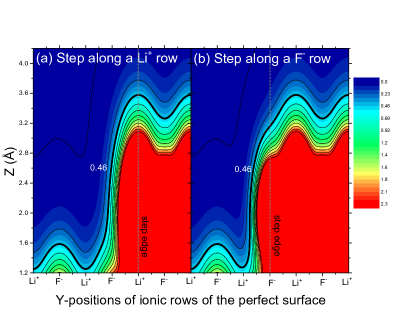
Taking into consideration that the transverse length of the surface area that is probed by helium projectiles is much smaller than the axial one, in Fig. 10 we show two-dimensional angular distributions for surface steps along the channel considering closer distances to the focus point of the beam, that is, Å in Fig. 10 (a) and Å in Fig. 10 (b). These steps are placed respectively on top of Li+ and F- rows of the ideal perfect surface. We found that the angular distributions of Fig. 10 are fully confined to the Laue circle, that is, all scattered projectiles leave the surface with , while the fraction of trajectories penetrating into the terrace bulk is lower than . Nonetheless, the presence of a parallel step in the area that is coherently illuminated by the atomic beam introduces an azimuthal asymmetry in the GIFAD patterns of Figs. 10 (a) and 10 (b), which display some interference maxima with structures elongated along the Laue circle. This latter effect depends on the exact position of the step, which determines the shape of the equipotential curves in the region of the terrace edge. In Fig. 11 we plot the equipotential curves, corresponding to surface potential averaged along the axial direction, for the two cases of Fig. 10. Around the step region, the equipotential contours vary if the terrace edge is along a Li+ or a F- row of the perfect surface. Similar differences in the equipotential curves are also observed for transverse terraces. But the influence of such border effects on GIFAD patterns seems to be stronger for parallel than for transverse upward steps.
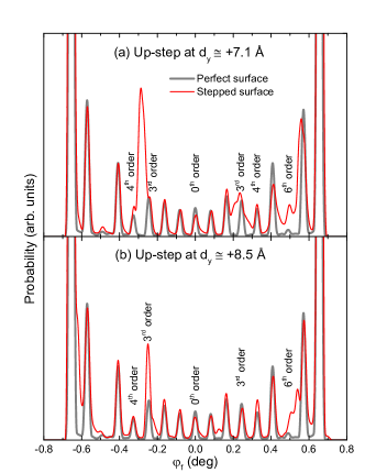
To investigate in more detail the asymmetry introduced by parallel steps, in Fig. 12 we plot the azimuthal spectra corresponding to the distributions of Fig. 10, contrasting them with that derived from a perfect crystal surface. In both panels of Fig. 12, the intensities of the Bragg peaks of order and increase as a consequence of the presence of the parallel step, while the central region of the spectrum is not affected by the surface defect. Furthermore, in Fig. 12 (a) the sharp increase of the -order maxima smudges the -order peak, both forming a broad intense peak on the left side of the projectile distribution, whereas in Fig. 12 (b), the peak of order is not altered by the terrace border.
IV Conclusions
In this work, the influence of surface defects on GIFAD patterns for the He/LiF(001) system was investigated by considering the presence of a monolayer step in the coherently illuminated region of the crystal target. Our theoretical description was based on the use the SIVR method to represent the grazing scattering process, combined with a PA atom-surface potential Miraglia2017 . This potential model allowed us to easily incorporate outward or inward monolayer terraces by adding or removing, respectively, an atomic layer in a portion of the LiF sample.
In order to simplify the analysis, only two different orientations of the terrace edge - transverse and parallel to the incidence channel - were considered. For transverse up-steps placed close to the focus point of the incident beam, at distances smaller than a few hundred Å, simulated projectile distributions display the characteristic Bragg peaks on the Laue circle, along with a diffuse background above the Laue circle, which presents additional central and outermost peaks. The upward step also affects the relative intensities of the on-Laue maxima, which are relevant for the use of GIFAD as a surface analysis technique. For transverse down-steps, instead, the projectile distribution approximates the one derived from a perfect crystal surface, while the terrace border introduces only a very weak background below the Laue circle, whose intensity is several orders of magnitude smaller than those of the on-Laue maxima. As expected, these terrace effects depend on the incidence conditions, gradually disappearing as increases.
On the other hand, as a consequence of the smaller transverse coherence length of the beam in the direction perpendicular to the axial channel, the presence of a parallel step affects the projectile distribution only if the step is placed at a distance less than a few tens Å from the focus point of the incident beam. In this case, the parallel up-step introduces an azimuthal asymmetry in the angular spectrum, which is fully localized on the Laue circle.
Summarizing, we found that terrace effects on GIFAD patterns strongly depend on the orientation of the edge of the monolayer terrace, as well as on the height (outward or inward) and the position of the step. Therefore, these findings suggest that GIFAD may be a useful tool to study terrace defects on alkali-halide surfaces. We hope that this study will be helpful to trigger experimental research on this topic.
Acknowledgements.
M.S.G is grateful to H. Khemliche for the helpful discussions. We acknowledge funding from ANPCYT (PICT-2017-1201; PICT-2017-2945; PICT-2020-1755; PICT-2020-1434) of Argentina.References
- [1] H. Winter and A. Schüller. Fast atom diffraction during grazing scattering from surfaces. Prog. Surf. Sci., 86:169–221, 2011.
- [2] M. Debiossac, P. Atkinson, A. Zugarramurdi, M. Eddrief, F. Finocchi, V. H. Etgens, A. Momeni, H. Khemliche, A. G. Borisov, and P. Roncin. Fast atom diffraction inside a molecular beam epitaxy chamber, a rich combination. Appl. Surf. Sci., 391:53–58, 2017.
- [3] A. Schüller, S. Wethekam, and H. Winter. Diffraction of Fast Atomic Projectiles during Grazing Scattering from a LiF(001) Surface. Phys. Rev. Lett., 98:016103, 2007.
- [4] P. Rousseau, H. Khemliche, A. G. Borisov, and P. Roncin. Quantum Scattering of Fast Atoms and Molecules on Surfaces. Phys. Rev. Lett., 98:016104, 2007.
- [5] A. Schüller, D. Blauth, J. Seifert, M. Busch, H. Winter, K. Gärtner, R. Włodarczyk, J. Sauer, and M. Sierka. Fast atom diffraction during grazing scattering from a MgO(001) surface. Surf. Sci., 606:161–173, 2012.
- [6] M. Debiossac, A. Zugarramurdi, H. Khemliche, P. Roncin, A. G. Borisov, A. Momeni, P. Atkinson, M. Eddrief, F. Finocchi, and V. H. Etgens. Combined experimental and theoretical study of fast atom diffraction on the reconstructed GaAs(001) surface. Phys. Rev. B, 90:155308, 2014.
- [7] C. A. Ríos Rubiano, G. A. Bocan, M. S. Gravielle, N. Bundaleski, H. Khemliche, and P. Roncin. Ab initio potential for the He-Ag(110) interaction investigated using grazing-incidence fast-atom diffraction. Phys. Rev. A, 87:012903, 2013.
- [8] A. Schüller, M. Busch, S. Wethekam, and H. Winter. Fast Atom Diffraction from Superstructures on a Fe(110) Surface. Phys. Rev. Lett., 102:017602, 2009.
- [9] J. Seifert, A. Schüller, H. Winter, R. Włodarczyk, J. Sauer, and M. Sierka. Diffraction of fast atoms during grazing scattering from the surface of an ultrathin silica film on Mo(112). Phys. Rev. B, 82:035436, 2010.
- [10] J. Seifert, M. Busch, E. Meyer, and H. Winter. Surface Structure of Alanine on Cu(110) Studied by Fast Atom Diffraction. Phys. Rev. Lett., 111:137601, 2013.
- [11] A. Momeni, E. M. Staicu Casagrande, A. Dechaux, and H. Khemliche. Ultrafast Crystallization Dynamics at an Organic-Inorganic Interface Revealed in Real Time by Grazing Incidence Fast Atom Diffraction. J. Phys. Chem. Lett., 9:908–913, 2018.
- [12] A. Zugarramurdi, M. Debiossac, P. Lunca-Popa, A. J. Mayne, A. Momeni, A. G. Borisov, Z. Mu, P. Roncin, and H. Khemliche. Determination of the geometric corrugation of graphene on SiC(0001) by grazing incidence fast atom diffraction. Appl. Phys. Lett., 106:101902, 2015.
- [13] D. Farias, M. Patting, K.-H. Rieder, and J. R. Manson. Scattering of He atoms from surface defects by grazing-angle diffraction beams. Phys. Rev. B, 65:165435, 2002.
- [14] E. Meyer, H . Heinzelmann, P. Grütter, Th. Jung, Th. Weisskopf, H.-R. Hidber, R. Lapka, H. Rudin, and H.-J. Güntherodt. Comparative study of lithium fluoride and graphite by atomic force microscopy (AFM). J. Microsc., 152:269–280, 1988.
- [15] T. Prohaska, G. Friedbacher, and M. Grasserbauer. In-situ investigation of surface reactions on alkali halides by atomic force microscopy. Fresenius J. Anal. Chem., 349:190–194, 1994.
- [16] R. Vidal, J. Ferrón, C. I. Meyer, V. Quintero Riascos, and F. Bonetto. The influence of surface defects on the low energy scattering of Ar ions from a Cu(111) surface. Surf. Sci., 690:121482, 2019.
- [17] C. Díaz and M. S. Gravielle. Grazing incidence fast atom and molecule diffraction: theoretical challenges. Phys. Chem. Chem. Phys., 24:15628–15656, 2022.
- [18] M. Debiossac, P. Pan, and P. Roncin. Grazing Incidence Fast Atom Diffraction, similarities and differences with thermal energy atom scattering (TEAS). Phys. Chem. Chem. Phys., 23:7615, 2021.
- [19] M. S. Gravielle and J. E. Miraglia. Semiquantum approach for fast atom diffraction: Solving the rainbow divergence. Phys. Rev. A, 90:052718, 2014.
- [20] M. S. Gravielle and J. E. Miraglia. Influence of beam collimation on fast-atom diffraction studied via a semiquantum approach. Phys. Rev. A, 92:062709, 2015.
- [21] J. E. Miraglia and M. S. Gravielle. Reexamination of the interaction of atoms with a LiF(001) surface. Phys. Rev. A, 95:022710, 2017.
- [22] M. S. Gravielle, J. E. Miraglia, and G. A. Bocan. State-of-the-Art Reviews on Energetic Ion-Atom and Ion-Molecule Collisions , volume 2, chapter 7. World Scientific Publishing, Singapore, 2019.
- [23] L. Frisco, J. E. Miraglia, and M. S. Gravielle. Spot-beam effect in grazing atom-surface collisions: from quantum to classical. J. Phys.: Condens. Matter, 30:405001, 2018.
- [24] M. S. Gravielle, J. E. Miraglia, and L. Frisco. Coherence-Length Effects in Fast Atom Diffraction at Grazing Incidence. Atoms, 6:64, 2018.
- [25] F. Ito, K. Kobayashi, P. Spijker, L. Zivanovic, K. Umeda, T. Nurmi, N. Holmberg, K. Laasonen, A. S. Foster, and H. Yamada. Molecular Resolution of the Water Interface at an Alkali Halide with Terraces and Steps. J. Phys. Chem. C, 120:19714–19722, 2016.
- [26] A. Schüller and H. Winter. Difraction of fast atoms under axial surface channeling conditions. Nucl. Instr. Methods Phys. Res. B, 267:628–633, 2009.
- [27] A. Schüller, H. Winter, M. S. Gravielle, J. M. Pruneda, and J. E. Miraglia. He-LiF surface interaction potential from fast atom diffraction. Phys. Rev. A, 80:062903, 2009.
- [28] G. A. Bocan, H. Breiss, S. Szilasi, A. Momeni, E. M. Staicu Casagrande, M. S. Gravielle, E. A. Sánchez, and H. Khemliche. Anomalous KCl(001) Surface Corrugation from Fast He Diffraction at Very Grazing Incidence. Phys. Rev. Lett., 125:096101, 2020.
- [29] A. Schüller and H. Winter. Supernumerary Rainbows in the Angular Distribution of Scattered Projectiles for Grazing Collisions of Fast Atoms with a LiF(001) Surface. Phys. Rev. Lett., 100:097602, 2008.
- [30] M. Debiossac and P. Roncin. Image processing for grazing incidence fast atom diffraction. Nucl. Instr. Methods Phys. Res. B, 382:36–41, 2016.
- [31] A. Zugarramurdi and A.G. Borisov. Transition from fast to slow atom diffraction. Phys. Rev. A, 86:062903, 2012.
- [32] A. S. Muzas, F. Gatti, F. Martín, and C. Díaz. Diffraction of H from LiF(001): From slow normal incidence to fast grazing incidence. Nucl. Instr. Methods Phys. Res. B, 382:49–53, 2016.