Characterizing the Performance of Node-Aware Strategies for Irregular Point-to-Point Communication on Heterogeneous Architectures
Abstract
Supercomputer architectures are trending toward higher computational throughput due to the inclusion of heterogeneous compute nodes. These multi-GPU nodes increase on-node computational efficiency, while also increasing the amount of data to be communicated and the number of potential data flow paths. In this work, we characterize the performance of irregular point-to-point communication with MPI on heterogeneous compute environments through performance modeling, demonstrating the limitations of standard communication strategies for both device-aware and staging-through-host communication techniques. Presented models suggest staging communicated data through host processes then using node-aware communication strategies for high inter-node message counts. Notably, the models also predict that node-aware communication utilizing all available CPU cores to communicate inter-node data leads to the most performant strategy when communicating with a high number of nodes. Model validation is provided via a case study of irregular point-to-point communication patterns in distributed sparse matrix-vector products. Importantly, we include a discussion on the implications model predictions have on communication strategy design for emerging supercomputer architectures.
keywords:
performance modeling , GPU , data movement , CUDA-aware , GPUDirect , MPI , parallel , communication , sparse matrixWGMwgm\xspace \csdefQEqe\xspace
[uiuc]organization=University of Illinois at Urbana-Champaign, addressline=Department of Computer Science, city=Urbana, postcode=61801, state=IL, country=USA
[unm]organization=University of New Mexico, addressline=Department of Computer Science, city=Albuquerque, postcode=87131, state=NM, country=USA
1 Introduction
Modern parallel supercomputers exhibit increasingly higher computational throughput due to the inclusion of multiple GPUs per node — see Section 2.1. These GPUs operate on much higher data volumes concurrently than previous CPU-only clusters, yet the issue of communication bottlenecks persists and is exacerbated in a multi-node–multi-GPU setting. While the high computational intensity of modern supercomputers is driving a new era of applications, the volume of data communicated between compute units has also increased, creating new hurdles for data movement performance.
In this paper, we focus on irregular point-to-point communication, which generates a performance bottleneck in parallel solvers and graph algorithms due to the prevalence of sparse matrix operations and unstructured mesh computations [1, 2]. We aim to characterize the performance of various irregular point-to-point communication strategies using MPI within heterogeneous compute environments via performance modeling, which suggests the extension of node-aware communication strategies for inter-CPU communication (discussed in Section 2.3) onto heterogeneous architectures.
Node-aware communication schemes take advantage of the fact that the performance of communication depends on the relative location of communicating processes. These schemes reduce communication times by exchanging more costly data flow paths for cheaper ones when possible [3]. While there are many potential paths for data movement on heterogeneous architectures, we consider the communication paths available via the MPI API and only consider device specific optimizations, such as utilizing CUDA Multi-Process Service (MPS) to allow multiple MPI ranks to copy data from a single GPU, for the purpose of comparison.
In Section 3, we present modeling parameters for all potential data flow paths between CPUs and GPUs, which are then used within performance models to predict the cost of various node-aware communication schemes when implemented on heterogeneous architectures in Section 4. Models are first validated via comparison against the performance of communication within a sparse matrix-vector product, then further modeling results are shown suggesting that for large message counts, optimal performance is achieved when GPU data is staged through a host process and split across multiple processes before communicating through the network.
Furthermore, Section 5 provides a study of the techniques modeled in Section 4 when applied to the irregular point-to-point communication patterns in distributed sparse matrix-vector multiplication (SpMV) on heterogeneous architectures, further validating model predictions. Finally, Section 6 provides a discussion on the implications model predictions and benchmark results have on the future of communication strategy design for emerging supercomputer architectures, alongside a summary of the presented results.
The following provides a summary of paper contributions:
-
1.
performance models for node-aware communication on heterogeneous architectures — Sections 3 and 4;
-
2.
performance predictions for common irregular point-to-point communication scenarios using the developed models — Section 4.6;
-
3.
benchmarks of irregular point-to-point communication patterns found within distributed sparse matrix-vector multiplication — Section 5; and
-
4.
remarks on future communication design for emerging supercomputer architectures — Section 6.
2 Background
2.1 Modern Architectures
Many current large-scale supercomputers consist of heterogeneous nodes containing multiple GPUs connected to a single CPU per socket with two sockets per node.
In the case of the Lassen supercomputer, each socket consists of a single IBM Power9 CPU connected to two NVIDIA V100 GPUs [4] (see Figure 2.1), while the Summit supercomputer has a single IBM Power9 CPU connected to three NVIDIA V100 GPUs [5]. For both machines, each CPU has 20 available cores, CPUs and GPUs are connected via NVLink, and nodes are connected via Mellanox EDR 100G InfiniBand in a non-blocking fat tree topology. Upcoming Department of Energy exascale machines, Frontier [6] and El Capitan111https://www.llnl.gov/news/el-capitan-testbed-systems-rank-among-top-200-worlds-most-powerful-computers, will have nodes with a similar structure to those found in Lassen and Summit. However, these compute nodes will consist of a single socket housing an AMD EPYC CPU connected to four AMD Instinct 250X GPUs via AMD Infinity Fabric with a Slingshot network. Additionally, the National Center for Supercomputing Applications (NCSA) will boast more expansive compute nodes consisting of four to eight AMD A100 GPUs connected to a dual AMD 64-core 2.55 GHz Milan processor per compute node in their upcoming system Delta222https://www.ncsa.illinois.edu/research/project-highlights/delta.
Both current and future supercomputers boast heterogeneous architectures with multiple paths for data movement between two GPUs. Two connected GPUs either exchange data directly or stage through the host CPU by first copying data to CPU memory, then transferring data from the local CPU to the host CPU of the receiving GPU, and finally copying received data to the destination GPU. The process of staging data through the host CPU can be used for any set of communicating GPUs independent of their relative locations. However, device-aware data movement paradigms, such as CUDA-aware MPI using GPUDirect [7] on Lassen, remove the necessity of copying data to the host CPU and allow data to be pulled directly from device memory, even in the case of inter-node data transfers. The addition of device-aware technologies increases the number of potential data movement paths necessitating the use of robust performance modeling to determine communication bottlenecks, as well as, design optimal communication strategies.
2.2 Modeling Data Movement
Throughout this paper, we rely on the max-rate model as the basis for communication modeling [8]. The max-rate model is an improvement to the standard postal model of communication, accounting for injection limits into the network. The traditional postal model estimates the cost of communicating a message between two symmetric multiprocessing (SMP) nodes as
| (2.1) |
where is the latency, is the per-byte transfer cost, and is the number of bytes being communicated. The max-rate model adds parameters for injection-bandwidth limits and the number of actively communicating processes, resulting in the following time estimation,
| (2.2) |
where is again the latency, is the maximum number of messages sent by a single process on a given node, is the maximum number of bytes sent by a single process on a given SMP, ppn is the number of processes per node, is the rate at which a network interface card (NIC) can inject data into the network, and is the rate at which a process can transport data. When , this model reduces to the postal model.
For inter-CPU communication, additional improvements are available to the max-rate model within the context of irregular point-to-point communication. Additional hardware and software overhead penalties are represented in the LogP model[9], which is extended to include long message costs in the LogGP model[10]. The importance of modeling queue search times and network contention on accurately predicting performance, for example, is shown in [11]. The additional parameters needed to account for contention and queue times motivates design decisions within the context of node-aware communication techniques, highlighting trade-offs between communication schemes. Node-aware communication strategies are discussed in more detail in Section 2.3.
The max-rate model also applies to inter-GPU communication [12]. Here, the noted difficulty in reaching injection bandwidth limits with inter-GPU communication is due to the low number of communicating GPUs per node. Additionally, for large message counts, performance benefits are observed [12] when staging communication between GPUs through host CPUs. In Section 4, the models for inter-GPU irregular point-to-point communication are presented.
2.3 Node-Aware Communication
Node-aware communication techniques for irregular point-to-point communication have been designed within the context of sparse matrix-vector multiplication (SpMV) and sparse matrix-matrix multiplication (SpMM) [3]. Due to their low computational requirements, sparse matrix operations often incur a large communication overhead when performed in a parallel distributed setting, highlighting the limitations of standard communication practices.
There are two redundancies that occur with standard communication, namely: a message redundancy and a data redundancy, illustrated in Figure 2.2. First, each node injects many messages into the network; for example, some nodes send multiple messages to a single process on the destination node creating message redundancy. Second, processes send their local data to every destination process, independent of whether they had sent the same local data to another process on the same node; hence a redundancy in data being sent through the network.
The majority of node-aware communication work has been done within the context of CPU to CPU communication with a subset of this work later replicated for GPU to GPU communication. There are three types of node-aware communication for CPU to CPU communication, each eliminating all or some of the redundancies introduced by standard communication.
2.3.1 3-Step
3-Step node-aware communication, first introduced in [3], eliminates both redundancies in standard communication by gathering all necessary data to be sent off-node in a single buffer. Pairing all processes with a receiving process on distinct nodes ensures efficiency of the method by making sure every process remains active throughout the communication scheme.
First, all messages sent to a separate node are gathered in a buffer by the single process associated with the node. Secondly, this process sends the data buffer to the paired process on the receiving node. Thirdly, the paired process on the receiving node redistributes the data to the correct destination processes on-node. An example of these steps is outlined in Figure 2.3.
As noted in [3], the method can be extended to include further breakdown of data exchanges to include intra-socket data communication before the intra-node communication phase. However, we expect minimal performance benefits in extending the communication strategy throughout the entire node hierarchy for CPU to CPU communication. Instead, this strategy is adopted for GPU to GPU communication in [13], where the full hierarchy of the node is utilized to achieve optimal performance due to the fast data transfer rates of socket-level GPU interconnects on Summit [5]. In addition, recent work on utilizing neighborhood collectives in conjunction with the 3-Step node-aware communication strategy further reduces communication overhead in sparse solvers [14].
2.3.2 2-Step
When communicating high data volumes between nodes, 3-Step communication can see limitations as the single buffer communicating data grows extremely large, thus motivating a 2-Step node-aware technique as in [15]. The 2-Step technique eliminates the redundancy of sending duplicate data through the network, but does not reduce the redundancy of multiple messages being sent between nodes. In 2-Step, each process exchanges information needed by the receiving node with their paired process directly, followed by the receiving node redistributing the messages on-node, as shown in Figure 2.4. Overall, the total number of bytes communicated with 3-Step and 2-Step communication techniques is the same, but the number and size of inter-node messages differs.
2.3.3 Split
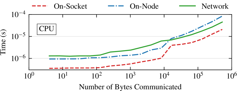
3-Step and 2-Step communication show a drastic difference in performance in communicating on-node versus inter-node messages [3], particularly on more traditional networks, e.g., the now retired BlueWaters system. Yet this is not always the case for more recent interconnects, such as on Lassen, which shows varying performance for inter-node versus intra-node communication depending on the amount of data being communicated — see Figure 2.5.
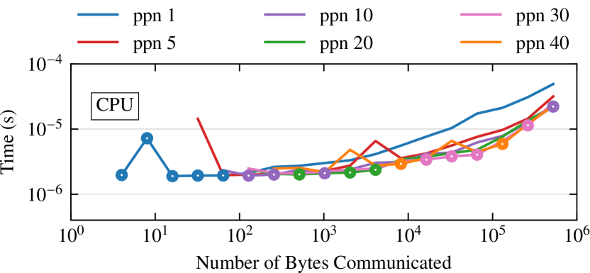
In addition to network communication being faster than on-node communication for large message sizes, the CPUs used in current supercomputers have high numbers of cores (for example, the IBM Power9 has 40 available cores on Lassen, and the Delta system has 64 available cores on each AMD Milan processor), making splitting large data volumes across all available cores more performant than when the entire data volume is sent by a single process — see Figure 2.6.
Split communication, as introduced in [16], addresses the variable performance of 3-Step and 2-Step node-aware communication on modern supercomputers. This communication technique balances the performance of multi-step communication by splitting the communicated inter-node data into messages of size message_cap, followed by a distribution across some number of on-node processes before being injected into the network. Pseudo-code of the setup is provided in Algorithm 1 with communication parameters defined in Table 1. Here, we detail the operations summarized in Algorithm 1.
| Parameter | Description |
|---|---|
| message_cap | maximum message size when splitting communicated inter-nodal data volumes |
| total_IN_recv_vol | total amount of data being received by this node from any other node in Bytes |
| max_IN_recv_size | maximum amount of data being received from a single other node in Bytes |
| num_IN_nodes | number of nodes from which this node is receiving any messages |
| PPN | processes per node |
- Line 8
-
The algorithm begins by splitting inter-node messages by their origin node (on-node or off-node).
- Line 9
-
A local communicator is created for exchanging all messages with origin on-node.
- Line 10
-
All messages with origin off-node are split into lists according to their origin node.
- Lines 11
-
Parameters, such as the number of nodes from which this node receives, the maximum amount of data being received from a single other node, and the total amount of data being received from any node by this node, are determined.
- Lines 12–17
-
In this block of the algorithm, the appropriate
message_cap is determined.- Lines 12–13
-
First, the maximum amount of data being received from any node is checked to determine if it is smaller than the user provided message_cap. When this occurs, every node’s data should be sent in a single message.
- Lines 14–17
-
Otherwise, if the total inter-node data volume being communicated divided by the provided message_cap is greater than the active number of processes per node, then the message_cap is increased to be the total inter-node data volume divided by the number of on-node processes.
- Line 18
-
On-node processes are assigned inter-node messages to receive in descending order of size, starting with local rank 0. Inter-node messages to be sent are assigned in the reverse order starting with local rank PPN-1. This in combination with the message splitting ensures that all processes are active during communication.
- Line 19
-
A local communicator is created for redistributing all received inter-node data to its final destination processes on-node.
- Line 20
-
A global communicator is created for exchanging inter-node messages based on send and receive message assignment in Line 18.
- Line 21
-
A local communicator is created for redistributing all inter-node data to be sent by this node to the local processes responsible for sending the inter-node messages.
Algorithm 2 provides the steps for performing Split communication once the relevant communicators have been created. Depending on the computation in which Split communication is being used, Algorithms 2, 2 and 2 of Algorithm 2 can be overlapped with various pieces of the computation — details of overlapping computation with node-aware communication can be found in [3]. Furthermore, in [16], the inter-node message size cutoff is determined by the rendezvous protocol based on communication modeling for Lassen, but it is observed that the message size cutoff can be determined via tuning or any other chosen criteria. Similarly, we use a message size cutoff of three in Figure 2.7 to demonstrate the multi-step technique when communicating between two nodes with four processes each.
Splitting communication eliminates the data redundancy from standard communication, but does so with varying numbers of inter-node messages (as determined by the total data volume being sent to another distinct node). Within the context of a sparse matrix-block vector multiplication, this scheme yields up to speedup over standard communication techniques. The goal of this work is to consider approaches similar to the split communication strategy within the context of heterogeneous architectures.
2.4 Distributed Sparse Matrix-Vector Multiplication
Throughout the paper, we utilize the irregular point-to-point communication patterns induced by sparse matrix-vector multiplication (SpMV) to test the performance potential of node-aware communication strategies within the context of GPU to GPU communication, as well as provide further model validation. A SpMV, defined as
| (2.3) |
with and , , is a common kernel in sparse iterative methods. Distributed SpMVs performed on GPUs currently face many performance hurdles including computational inefficiencies of the local SpMV portion on each GPU, packing and unpacking communication buffers, strategically overlapping computation and communication, etc. [17, 18]. There are multiple potential solutions to these problems, many of which are still currently being researched [19, 20, 21].
Because the presented work focuses on general communication strategies, we do not attempt to optimize these portions of the distributed SpMV. Instead our performance tests focus solely on benchmarking the irregular point-to-point communication that occurs in the distributed kernel, characterizing the performance of multiple communication strategies for various communicated data volumes and message counts on a heterogeneous architecture.
2.4.1 Testing Setup
All performance tests presented in Sections 4.5 and 5 correspond to a distributed SpMV with , , and partitioned row-wise across GPUs with contiguous rows stored on each GPU (see Figure 2.8). In addition, the rows of on each GPU are presumed to be split into two blocks, namely on-GPU and off-GPU. The on-GPU block is the diagonal block of columns corresponding to the on-GPU portion of rows in and , and the off-GPU block contains the matrix ’s nonzero values correlating to non-local rows of and stored off-GPU. This splitting is common practice, as it differentiates between the portions of a SpMV that require communication, as well as making the distributed kernel a perfect case study for node-aware communication performance on heterogeneous architectures. Because our key goal is to characterize irregular point-to-point communication performance independent of the distributed operation in which it is included, all presented benchmarks throughout the paper focus on the communication patterns induced by the distributed SpMV and not the computational aspects of the operation. We would like to note that within the context of a distributed SpMV, optimal performance depends on some combination of communication and computation overlap. However, optimizing the entire distributed SpMV operation lies outside the scope of this paper, thus timings for the computational portion and on-device kernel details are excluded.
3 Modeling Parameters for Communication
When data is moved between two GPUs on separate nodes using MPI, the data can be moved in one of two ways:
-
Device-aware: data is sent directly from the sending GPU through the NIC and the network to the receiving GPU without being copied to the host CPU; and
-
Staged-through-host: data is copied to the host CPU before being sent through the NIC and the network to the receiving GPU’s host CPU then copied to the receiving GPU.
Because both of these involve moving data through the GPU and possibly the CPU, it is important to consider the cost of transmitting data through all possible data flow paths involving the CPU or GPU.
Throughout this section and the remainder of the paper, results are presented for the Spectrum MPI implementation on Lassen [4] In [12], it is shown that Lassen and Summit [5] demonstrate similar performance using Spectrum MPI (there, the MPI implementation is optimized for use on the two DOE machines), therefore results for a single machine are provided. Moreover, each of the presented model parameters is the result of ping-pong and node-pong timings collected through BenchPress333https://github.com/bienz2/BenchPress, a node architecture-aware library used for benchmarking data movement performance on large-scale systems. The ping-pong and node-pong tests are performed for 1000 iterations and averaged; each model parameter is then given by a linear least-squares fit to the collected data.
We use the postal model presented in Equation 2.1 to model the time required for sending a single message between two CPUs or two GPUs, with the measured parameters for Lassen presented in Table 2. The and parameters are separated based on where the two processes are physically located with respect to one another, namely on the same socket, on different sockets but the same node, or separate nodes. In addition, the parameters are split further based on messaging protocol:
- short
-
fits in the envelope so the message is sent directly to the receiving process;
- eager
-
assumes adequate buffer space is already allocated by the receiving process; or
- rendezvous
-
requires the receiving process to allocate buffer space for the message before the data is sent.
The short protocol has been excluded from the GPU messaging parameter portion of Table 2 because this protocol is not used in device-aware communication on Lassen.
| on-socket | on-node | off-node | |||
|---|---|---|---|---|---|
| inter-CPU | Short | 3.67e-07 | 9.25e-07 | 1.89e-06 | |
| 1.32e-10 | 1.19e-09 | 6.88e-10 | |||
| Eager | 4.61e-07 | 1.17e-06 | 2.44e-06 | ||
| 7.12e-11 | 2.18e-10 | 3.79e-10 | |||
| Rend | 3.15e-06 | 6.77e-06 | 7.76e-06 | ||
| 3.40e-11 | 1.49e-10 | 7.97e-11 | |||
| inter-GPU | Eager | 1.87e-06 | 2.02e-05 | 8.95e-06 | |
| 5.79e-11 | 2.15e-10 | 1.72e-10 | |||
| Rend | 1.82e-05 | 1.93e-05 | 1.10e-05 | ||
| 1.46e-11 | 2.39e-11 | 1.72e-10 | |||
[sec] [sec/byte]
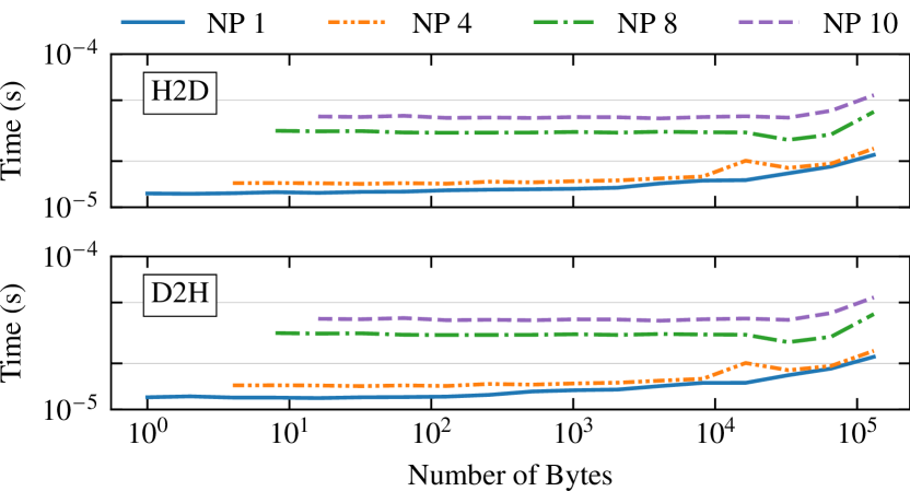
Because staging data through a host process requires copying data to the sending host CPU and from the receiving GPU’s host process, measured parameters for cudaMemcpyAsync are included in Table 3 with distinction between whether the copy is using a single process or four processes to move data from the device. We assume that all data copies will occur on-socket, and we do not consider cases with more than four processes pulling data from a single GPU at a time as there was no observed benefit in splitting data copies further across multiple processes — see Figure 3.1.
| HostToDevice | DeviceToHost | ||
|---|---|---|---|
| 1 proc | 1.30e-05 | 1.27e-05 | |
| 1.85e-11 | 1.96e-11 | ||
| 4 proc | 1.52e-05 | 1.47e-05 | |
| 5.52e-10 | 1.50e-10 | ||
[sec] [sec/byte]
In addition to considering the postal model for inter-CPU and inter-GPU communication, the max-rate model presented in Equation 2.2 is required for accurately predicting the performance of staging GPU data through a host process when using more than a single process per node. Therefore, the measured injection bandwidth limit for inter-CPU communication is presented in Table 4. The inter-GPU injection bandwidth limit is excluded, as these limits are not reached with the four available GPUs per node on Lassen.
| [bytes/sec] | |
| inter-CPU | 4.19e-11 |
Using the measured modeling parameters, we now model the performance of various communication strategies based on the node-aware techniques discussed in Section 2.3.
4 Modeling Node-Aware Strategies for Inter-Node Communication
In this section, we present performance models for existing node-aware strategies using device-aware and staged-through-host communication for inter-node data exchanges on Lassen, though these models do extend to any machine with two sockets per node. For each node-aware case, the models are divided into the time spent in on-node communication (Sections 4.1 and 4.2), off-node communication (Section 4.3), and data copies, in the case of staged-through-host communication (see Section 4.4). The models themselves do not consider the removal of duplicate data discussed in Section 2.3, as the amount of duplicate data injected into the network is operation and problem dependent. However, adapting the input parameters for the models to reflect the removal of duplicate data is straightforward and done in Section 4.6.
Performance is modeled for standard communication and all node-aware communication strategies discussed in Section 2.3. We consider staged-through-host and device-aware communication for all of the strategies except for the split strategies, for which device-aware communication does not apply. “Split + MD” first copies data to a single host process, then splits the inter-node data to be communicated across multiple processes via extra on-node inter-CPU messages. “Split + DD” uses duplicate device pointers to copy data from a GPU to multiple host process, reducing the number of on-node messages required to split the inter-node data volume being communicated. Each GPU is assumed to have a single host process except in the case of “Split + DD”. For reference, the modeled communication strategies are listed in Table 5.
| Staged-through-host | Device-aware | |
|---|---|---|
| Standard | ✓ | ✓ |
| 3-Step | ✓ | ✓ |
| 2-Step | ✓ | ✓ |
| Split + MD | ✓ | |
| Split + DD | ✓ |
4.1 Modeling On-Node Communication for 3-Step and 2-Step
For 3-Step communication, all data originating on any GPU on node with a destination of any GPU on node is first gathered locally. In the worst-case scenario, all GPUs on node must contribute data for node , requiring communication among all GPUs per node. This is modeled as
| (4.1) |
where gps is the GPUs per socket and is the maximum message size sent by any single GPU.
The last step of both 2-Step and 3-Step communication involves redistributing data received via inter-node communication to its final destination GPU on-node. The worst case scenario for both strategies occurs when all of the data received via inter-node communication needs to be redistributed to every other GPU on-node. This is also modeled with Equation 4.1, with representing the maximum received inter-node message size.
4.2 Modeling On-Node Communication for Split
The split strategies require copying all data on node with destination of any GPU on node to the host processes before distributing the data across some number of on-node processes. Finally, each process sends data through the network. For large inter-node message sizes, the worst-case scenario occurs when a single GPU contains all data to be sent off-node with a data size large enough that it is split across all on-node processes. In the case of Lassen, there are a maximum of 40 on-node processes, therefore distributing the data would require an additional 19 on-socket messages and 20 off-socket/on-node messages if a single host process per GPU were being used. Generalizing the split strategy to any architecture using multiple host processes with duplicate device pointers yields
| (4.2) |
as the modeled time, where ppg is the number of host processes per GPU, and pps is the processes per socket, and is the total data volume to be communicated inter-node split across ppg.
Similar to the worst-case scenario for 3-Step and 2-Step on-node communication, the worst-case redistribution scenario for the split strategies is equivalent to Equation 4.2. In this case, a single GPU must redistribute all received inter-node data to every other GPU on-node; here, represents the total data volume received via inter-node communication split across ppg.
4.3 Modeling Off-Node Communication
For the off-node communication portion of each of the multi-step communication strategies, the max-rate model Equation 2.2 is used for routines that are staged-through-host, and the postal model Equation 2.1 is used for device-aware routines. For the max-rate model, the time spent in off-node communication is given by
| (4.3) |
for a number of messages to be communicated, , and a maximum number of bytes sent by a single process, where is the maximum number of bytes injected into the network by any single node. For device-aware communication, this reduces to the postal model
| (4.4) |
| Communication Strategy | Model | |
| Standard | Staged-through-host | Max-rate model Equation 2.2 |
| Device-aware | Postal model Equation 2.1 | |
| 3-Step | Staged-through-host | |
| Device-aware | ||
| 2-Step | Staged-through-host | |
| Device-aware | ||
| Split | Staged-through-host + MD | |
| Staged-through-host + DD | ||
4.4 Copy Parameter for Staged-through-Host Communication
The time required to copy data between the CPU and GPU is given by
| (4.5) |
where is the initial data copied from the source GPU, and is the final data copied to the destination GPU.
For all communication strategies except splitting with duplicate device pointers, a single process copies all data from a corresponding GPU. In the case of splitting with duplicate device pointers, we set the number of processes copying data simultaneously to four in our model. Parameters for both a single host process copying data and four host processes copying data simultaneously are presented in Table 3.
4.5 Model Validation
| Parameter | Description |
|---|---|
| max # of bytes sent by a single process/ GPU | |
| max # of bytes injected by a single node | |
| max # of bytes sent between any two nodes | |
| max # of nodes to which a processor sends | |
| max # of messages between any two nodes |
Table 6 presents the full models for the various communication strategies given in Table 5, which combine the preceding sub-models, with extra model parameters defined in Table 7 for clarity.
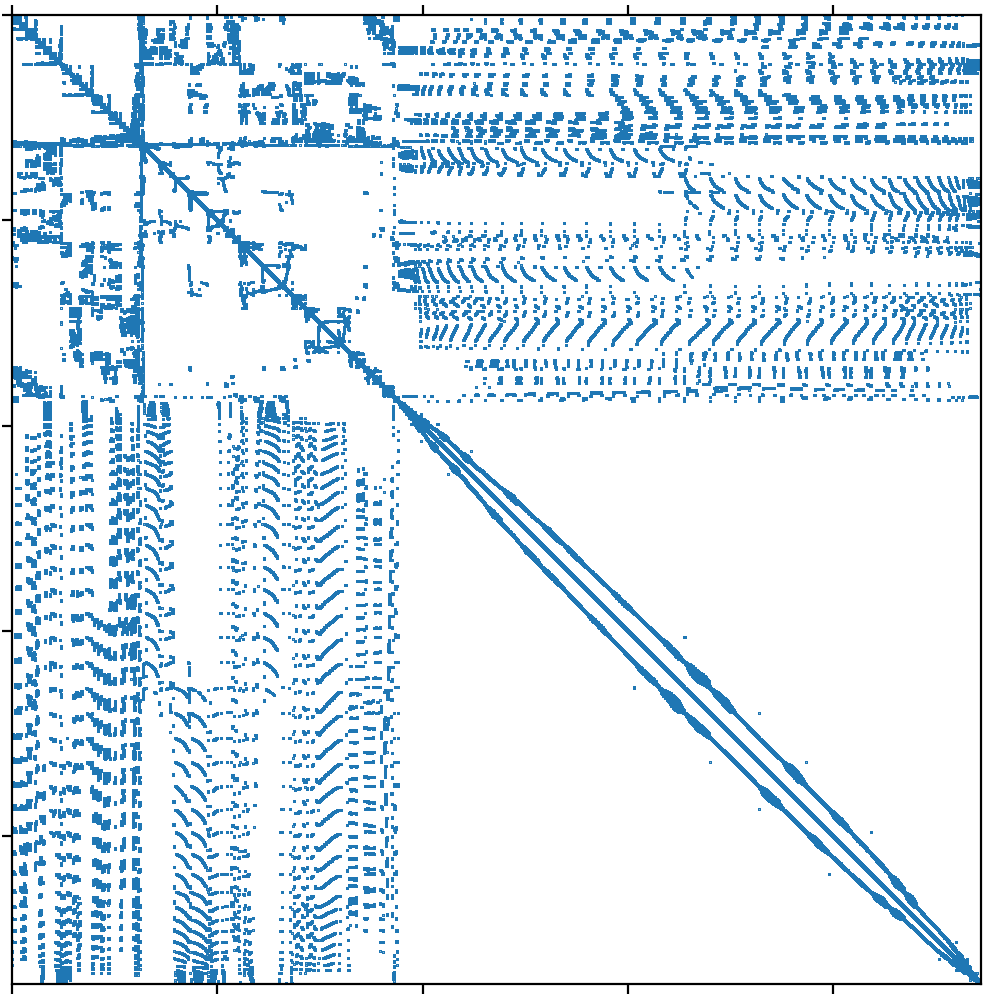
We provide a brief validation of the models via performance of the communication pattern induced by sparse matrix-vector multiplication (SpMV) with the audikw_1 matrix from the SuiteSparse matrix collection [22]. The matrix has rows and columns, and a nonzero density of 8.72e-05 with the associated sparsity pattern in Figure 4.1. Due to the high number of nonzero entries in the top rows and first columns of the matrix, the communication pattern associated with a SpMV for audikw_1 incurs high numbers of on-node and inter-node communication, therefore it is a perfect test case for validating the models which model the worst-case on-node communication scenarios for each of the communication strategies.
Figure 4.2 depicts the measured times (solid lines) for SpMV communication alongside model predictions (dotted lines). Presented measured times are the maximum average time required for communication by any single process for 1000 test runs. In the standard communication cases, the modeled times are an order of magnitude higher than actual measured times, but for the node-aware commmunication models, the predicted times provide a tight upperbound, generally on the same order of magnitude as the measured performance.
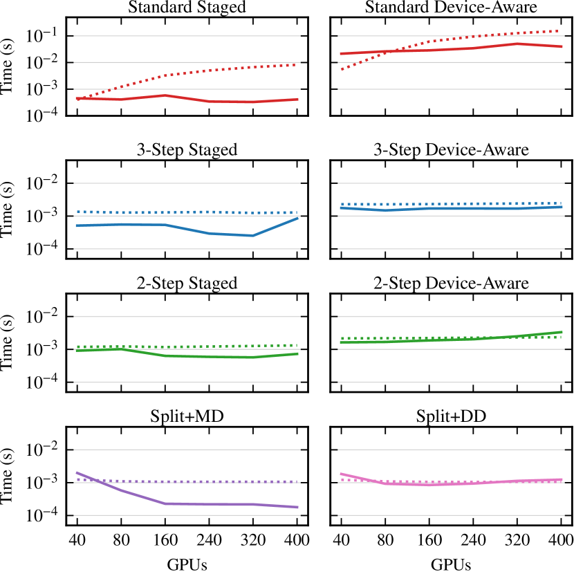
In Section 4.6, we use these models to predict the performance of common irregular point-to-point communication scenarios.
4.6 Modeled Performance
Figure 4.3 presents the modeled performance for common scenarios with irregular point-to-point communication, namely, a node sending a modest number of inter-node messages (32) and a large number of inter-node messages (256), with messages distributed evenly across on-node GPUs. Because the node-aware performance models are dependent upon the number of destination nodes, the models are split further, modelling if the data was being sent to 4 nodes (Figure 3(a)) or 16 nodes (Figure 3(b)). Additionally, the bottom rows of both Figure 3(a) and Figure 3(b) depict the impact of duplicate data removal on the node-aware communication strategies, by modelling their performance if 25% of the original data was duplicate data.
For each of these scenarios, we model the amount of time required for each node to send their messages to the destination nodes using standard communication. This modeled performance is compared against that of the various node-aware strategies where the messages are split and/or agglomerated accordingly. There are two cases presented for the 2-Step strategy, considering if every GPU on the source node is sending data to every GPU on the destination node (2-Step All), or if all the messages being sent to the destination node are from a single active GPU on the source node (2-Step 1). The message size cap for the split strategies is taken to be the same that was used in [16] and is the message cap used for switching to the rendezvous protocol on Lassen.
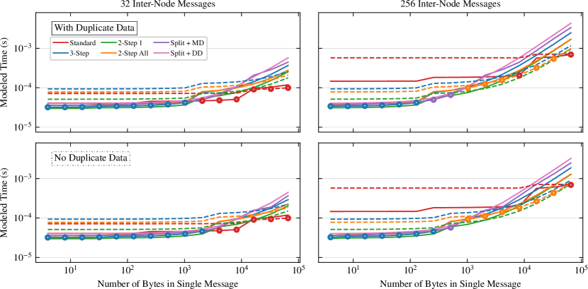
In Figure 4.3, we have circled the minimum modeled times for convenience, excluding the 2-Step 1 approaches, as they present the best-case scenario for 2-Step communication, which does not often occur in practice. However, we do think it is important to present these modeled times in order to depict a comprehensive picture of node-aware communication’s potential. For large message counts (256 Inter-Node Messages plots in Figure 4.3) and for message sizes greater than Bytes, device-aware 2-Step 1 is predicted to perform best, indicating that for high inter-node data volumes, if the on-node data was distributed such that every GPU on a given node was communicating with a distinct GPU on destination node , 2-Step communication would be best. This is consistent with the observed performance of the application-specific hierarchical communication in [13]. Now, we include discussion of the circled minimum times excluding the 2-Step 1 performance predictions.
In the case of a small number of messages injected into the network to a small number of nodes (Figure 3(a)), 3-Step and standard communication are observed as the most performant with Split+MD communication replacing 3-Step as the most performant for 16 nodes (Figure 3(b)). In both cases, the staged-through-host strategies predict the best performance until message sizes grow extremely large ( Bytes), where standard device-aware communication is modeled to be best. Device-aware communication is also modeled to be best for large message sizes when a node is injecting a large number of messages into the network. However, due to the high message volume, 3-Step and 2-Step device-aware strategies are predicted to have the optimal performance, due to their reduction in messages sent compared to standard communication.
Staged-through-host node-aware communication techniques model the best performance independent of number of destination nodes for all message sizes up to Bytes. When communicating with a small number of nodes (Figure 3(a)), 3-Step and 2-Step communication are often predicted to be the most performant, while Split+MD communication is predicted to be the most performant when communicating with a larger number of nodes (Figure 3(b)). This can be attributed to the use of all available processes on-node (40 in the case of Lassen), so that each individual process is injecting fewer messages into the network than in the case of 3-Step or 2-Step communication, where there is only a single process paired with each GPU (4 in the case of Lassen).
The device-aware node-aware strategies models present relatively large costs. However, this is unsurprising, considering the high overhead for inter-GPU communication on-socket and on-node (as indicated by the measured parameters in Table 2). The only cases for which device-aware node-aware strategies have improved performance over staged-through-host techniques is when the communicated inter-node data volume is extremely large, or assumed to have an optimal communication pattern (as in 2-Step 1).
Concerning the removal of duplicate data, there should be no impact on performance for small numbers of inter-node messages. A performance impact is noticed primarily when their is communication of a high inter-node data volume via a high number of messages. Once message sizes grow past Bytes in standard communication for all high message count models, removing duplicate data impacts which node-aware communication strategy could be most performant, switching from Split + MD to Split + DD or 2-Step to 3-Step, in the case of Figure 3(b).
Overall, the staged-through-host node-aware communication strategies model the best predicted performance for communication patterns requiring a high number of inter-node message exchanges. In Section 5, we benchmark the performance of the communication strategies within the context of sparse matrix-vector multiplication, verifying model predictions.
5 Benchmarking Sparse Matrix-Vector Multiplication Communication Patterns
In this section, we present performance results for the various communication strategies discussed throughout Sections 3 and 4 when applied to the communication patterns of a single distributed SpMV – see Section 2.4. For each of the strategies, each GPU is assumed to have a single host process, except in the case of “Split + DD” where four host processes are used. Additionally, for the split strategies, inter-node communicated data is potentially partitioned across up to 40 processes on-node (the maximum number of on-node processes for Lassen.) Our test matrices are a subset of the largest matrices in the SuiteSparse matrix collection [22]. For each benchmark, we performed 1000 test runs and present the maximum average time required for communication by any single process.
5.1 Results
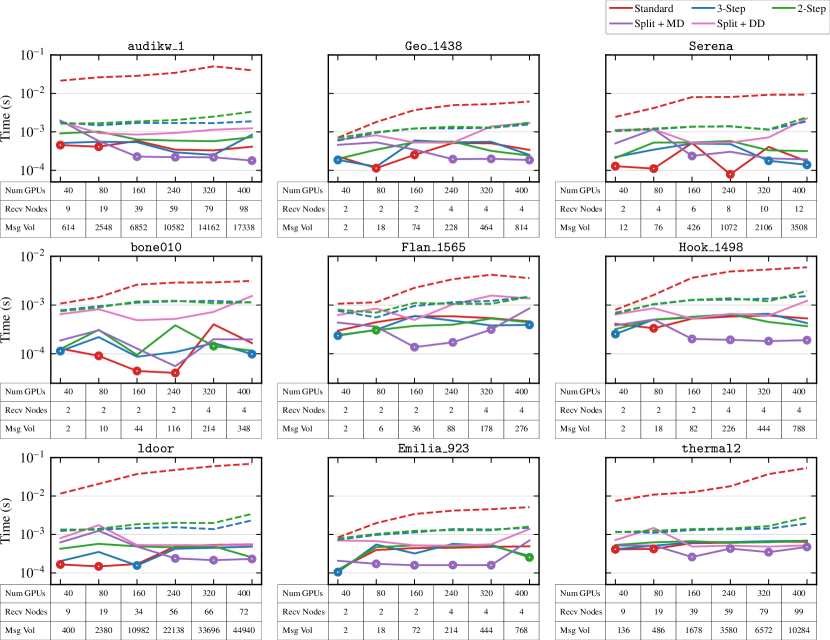
Figure 5.1 displays the distributed SpMV communication benchmark performance times for each communication strategy presented in Section 4 for each SuiteSparse matrix. Presented beneath each plot is the number of GPUs on which the SpMV is partitioned, the maximum number of nodes to which any single node is communicating (Recv Nodes), and the communicated inter-node message volume for standard communication.
Consistent with the majority of model predictions for large inter-node message volumes, the staged-through-host communication strategies exhibit far faster performance than the device-aware communication strategies. However, it is worth noting that device-aware 3-Step and device-aware 2-Step are typically much faster than standard device-aware communication. In the case of the thermal2 matrix, which exhibited a high inter-node message volume for standard communication, the gap between the device-aware node-aware strategies and staged-through-host communication strategies is smaller than for other matrices. Additionally, “Split + DD” consistently performed worse than “Split + MD”, consistent with modeled predictions. This is unsurprising considering the latency associated with using duplicate device pointers (1.5e-05 in Table 3) is much higher than the latency of sending on-socket messages (3.7e-07–3.2e-06 in Table 2) to distribute data being sent from a single GPU across multiple ranks.
The majority of the presented results are similar to the model prediction plots (Figure 4.3), where the fastest communication strategy was typically predicted to be one of the staged-through-host strategies: “Split + MD”, Standard, or “3-Step”. “Split + MD” exhibits the minimal performing time in most cases, except for smaller counts of participating GPUs (40 or 80 in the case of audikw_1, Serena, ldoor, thermal2), or for low inter-node message counts (bone010, Geo_1438) in which standard communication becomes more optimal.
Overall, staged-through-host node-aware communication strategies demonstrate the best performance for the majority of benchmarks, with “Split + MD” typically being the fastest, consistent with model predictions in Figure 3(b).
6 Conclusions and Future Work
The advancement of parallel computers has introduced the design of supercomputers with heterogeneous compute nodes due to the inclusion of multiple GPUs per node. For distributed applications, this typically results in larger communicated data volumes, as each compute unit can now operate on a larger partition of the problem. In addition to increased data volumes, the inclusion of multiple GPUs per node has increased the complexity of determining optimal data movement paths, particularly in the case of inter-node irregular point-to-point communication. In this work, we characterized the performance of irregular point-to-point communication between GPUs via modeling and introduced node-aware communication strategies to inter-node communication on heterogeneous architectures. Our models suggested the use of staged-through-host node-aware communication strategies, specifically split methods were indicated as potential top performers. These results were confirmed by a performance study on distributed SpMVs which saw split node-aware communication performing best in most cases, and typically much faster than standard device-aware communication.
Additionally, our work provides important groundwork on designing efficient communication strategies for the next generation of supercomputers. Future exascale machine architectures will include higher CPU core counts per node, alongside higher bandwidth interconnects (e.g., on Frontier, El Capitan, or Delta), two parameters that largely affect the performance of node-aware communication strategies. Based on the presented models, Split communication strategies will likely be the most efficient communication techniques to take advantage of the high bandwidth interconnects, but distributing data to be communicated across a larger number of on-node CPU cores could pose performance constraints. Because the models presented in Section 4 naturally extend to architectures with single socket nodes, future work includes plans to begin modeling the performance of machines resembling the next generation DOE exascale machines.
Acknowledgements
This material is based in part upon work supported by the Department of Energy, National Nuclear Security Administration, under Award Number DE-NA0003963 and DE-NA0003966.
References
-
[1]
M. Mohiyuddin, M. Hoemmen, J. Demmel, K. Yelick,
Minimizing communication in
sparse matrix solvers, in: Proceedings of the Conference on High Performance
Computing Networking, Storage and Analysis, SC ’09, Association for Computing
Machinery, New York, NY, USA, 2009, pp. 1–12.
doi:10.1145/1654059.1654096.
URL https://doi.org/10.1145/1654059.1654096 -
[2]
C. W. Smith, M. Rasquin, D. Ibanez, K. E. Jansen, M. S. Shephard,
Improving unstructured mesh
partitions for multiple criteria using mesh adjacencies, SIAM Journal on
Scientific Computing 40 (1) (2018) C47–C75.
doi:10.1137/15M1027814.
URL https://doi.org/10.1137/15M1027814 -
[3]
A. Bienz, W. D. Gropp, L. N. Olson,
Node
aware sparse matrix–vector multiplication, Journal of Parallel and
Distributed Computing 130 (2019) 166–178.
doi:https://doi.org/10.1016/j.jpdc.2019.03.016.
URL https://www.sciencedirect.com/science/article/pii/S0743731519302321 -
[4]
Lawrence Livermore National Laboratory,
Lassen (2022).
URL https://hpc.llnl.gov/hardware/compute-platforms/lassen -
[5]
Oak Ridge National Laboratory,
Summit (2022).
URL https://www.olcf.ornl.gov/summit -
[6]
Oak Ridge National Laboratories,
Frontier (2022).
URL https://www.olcf.ornl.gov/frontier -
[7]
S. Potluri, K. Hamidouche, A. Venkatesh, D. Bureddy, D. K. Panda,
Efficient inter-node
MPI communication using GPUDirect RDMA for Infiniband clusters with
NVIDIA GPUs, in: 2013 42nd International Conference on Parallel
Processing, 2013, pp. 80–89.
doi:10.1109/ICPP.2013.17.
URL https://ieeexplore.ieee.org/document/6687341 -
[8]
W. Gropp, L. N. Olson, P. Samfass,
Modeling MPI
communication performance on SMP nodes: Is it time to retire the ping pong
test, in: Proceedings of the 23rd European MPI Users’ Group Meeting, EuroMPI
2016, ACM, New York, NY, USA, 2016, pp. 41–50.
doi:10.1145/2966884.2966919.
URL http://doi.acm.org/10.1145/2966884.2966919 -
[9]
D. Culler, R. Karp, D. Patterson, A. Sahay, K. E. Schauser, E. Santos,
R. Subramonian, T. von Eicken,
LogP: Towards a realistic
model of parallel computation, SIGPLAN Not. 28 (7) (1993) 1–12.
doi:10.1145/173284.155333.
URL https://doi.org/10.1145/173284.155333 -
[10]
A. Alexandrov, M. F. Ionescu, K. E. Schauser, C. Scheiman,
LogGP:
Incorporating long messages into the LogP model for parallel computation,
Journal of Parallel and Distributed Computing 44 (1) (1997) 71 – 79.
doi:https://doi.org/10.1006/jpdc.1997.1346.
URL http://www.sciencedirect.com/science/article/pii/S0743731597913460 -
[11]
A. Bienz, W. D. Gropp, L. N. Olson,
Improving Performance Models
for Irregular Point-to-Point Communication, in: Proceedings of the 25th
European MPI Users’ Group Meeting, Barcelona, Spain, September 23-26,
2018, 2018, pp. 7:1–7:8.
doi:10.1145/3236367.3236368.
URL https://doi.org/10.1145/3236367.3236368 -
[12]
A. Bienz, L. N. Olson, W. D. Gropp, S. Lockhart,
Modeling data movement
performance on heterogeneous architectures, in: 2021 IEEE High Performance
Extreme Computing Conference (HPEC), 2021, pp. 1–7.
doi:10.1109/HPEC49654.2021.9622742.
URL https://ieeexplore.ieee.org/document/9622742 -
[13]
M. Hidayetoğlu, T. Bicer, S. G. de Gonzalo, B. Ren, V. De Andrade,
D. Gursoy, R. Kettimuthu, I. T. Foster, W.-m. W. Hwu,
Petascale XCT: 3D
Image Reconstruction with Hierarchical Communications on Multi-GPU Nodes,
in: Proceedings of the International Conference for High Performance
Computing, Networking, Storage and Analysis, SC ’20, IEEE Press, 2020, pp.
1–13.
URL https://dl.acm.org/doi/10.5555/3433701.3433750 -
[14]
A. Bienz, Sparse
neighborhood collectives on heterogeneous architectures, SIAM Conference
on Parallel Processing for Scientific Computing (2022).
URL https://meetings.siam.org/sess/dsp_talk.cfm?p=118711 -
[15]
A. Bienz, W. D. Gropp, L. N. Olson,
Reducing communication in
algebraic multigrid with multi-step node-aware communication, The
International Journal of High Performance Computing Applications 34 (5)
(2020) 547–561.
arXiv:https://doi.org/10.1177/1094342020925535, doi:10.1177/1094342020925535.
URL https://doi.org/10.1177/1094342020925535 -
[16]
S. Lockhart, A. Bienz, W. Gropp, L. Olson,
Performance analysis and optimal
node-aware communication for enlarged conjugate gradient methods (2022).
doi:10.48550/ARXIV.2203.06144.
URL https://arxiv.org/abs/2203.06144 -
[17]
J. Jenkins, J. Dinan, P. Balaji, N. F. Samatova, R. Thakur,
Enabling
fast, noncontiguous GPU data movement in hybrid MPI+ GPU environments,
in: 2012 IEEE International Conference on Cluster Computing, IEEE, IEEE
Computer Society, 2012, pp. 468–476.
doi:10.1109/CLUSTER.2012.72.
URL https://doi.ieeecomputersociety.org/10.1109/CLUSTER.2012.72 -
[18]
B. A. Page, P. M. Kogge, Scalability
of hybrid sparse matrix dense vector (SpMV) multiplication, International
Conference on High Performance Computing & Simulation (2018).
doi:10.1109/HPCS.2018.00072.
URL https://par.nsf.gov/biblio/10064735 -
[19]
W. Yang, K. Li, K. Li,
A
parallel computing method using blocked format with optimal partitioning for
SpMV on GPU, Journal of Computer and System Sciences 92 (2018) 152–170.
doi:https://doi.org/10.1016/j.jcss.2017.09.010.
URL https://www.sciencedirect.com/science/article/pii/S0022000017301587 -
[20]
B. A. Page, P. M. Kogge, Scalability
of hybrid SpMV with hypergraph partitioning and vertex delegation for
communication avoidance, in: International Conference on High Performance
Computing & Simulation (HPCS 2020), 2021, pp. 1–10.
URL https://par.nsf.gov/biblio/10298914 -
[21]
C.-H. Chu, K. S. Khorassani, Q. Zhou, H. Subramoni, D. K. Panda,
Dynamic kernel fusion for
bulk non-contiguous data transfer on GPU clusters, in: 2020 IEEE
International Conference on Cluster Computing (CLUSTER), 2020, pp. 130–141.
doi:10.1109/CLUSTER49012.2020.00023.
URL https://ieeexplore.ieee.org/document/9229601 -
[22]
T. A. Davis, Y. Hu, The
University of Florida sparse matrix collection, ACM Trans. Math. Softw.
38 (1) (Dec. 2011).
doi:10.1145/2049662.2049663.
URL https://doi.org/10.1145/2049662.2049663