Proactive and Resilient UAV Orchestration for QoS Driven Connectivity and Coverage of Ground Users
Abstract
Unmanned aerial vehicles (UAVs) are being successfully used to deliver communication services in applications such as extending the coverage of 5G cellular networks in remote areas, emergency situations, and enhancing the service quality in regions of dense user populations. While optimized placement solutions have been proposed in literature for ensuring quality of service (QoS) of users, they may not be ideal in highly mobile, autonomous, and diverse network scenarios. This paper proposes a proactive and resilient framework for distributed and dynamic orchestration of UAV small cells to provide QoS differentiation in the network. The UAV locations are tailored to end-user locations and service needs while ensuring that UAVs maintain localized backhaul connectivity. Simulation experiments show that under scenarios where physical placement can achieve service differentiation, the developed framework leads to a stable configurations of UAVs satisfying above 90% of user QoS requirements.
Index Terms:
Unmanned Aerial Vehicles, Connectivity, Resilience, Quality-of-Service, Swarming.I Introduction
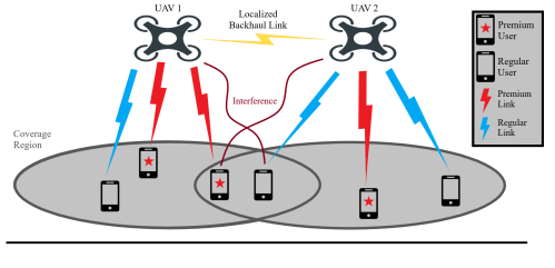
UAVs have proven to be a convenient choice for providing on-demand wireless connectivity in disasters and emergency scenarios [1]. They are also critical in enhancing and improving the service gaps in fifth generation (5G) cellular networks. In certain situations such as public events, gatherings, parades, or sporting events, there may be a need to supplement the cellular networks with small cell base stations (BSs) mounted on UAVs [2, 3]. While several factors play a role in the quality of communication experienced by the users connected to the UAVs, the placement the UAV BSs can be crucial in ensuring the strength of wireless signals between the UAV and the ground users [4]. Moreover, multiple types of users may be present in the network, e.g., those that have subscribed for higher speeds and preferred resource allocation, hereby referred to as premium users, and those that are using standard service, hereby referred to as regular users. Therefore, the placement of UAVs needs to be optimized to cater for the quality of service (QoS) requirements of different users [5, 6]. An illustration of the considered network scenario is shown in Fig. 1, where the premium user and regular user are connected to a network of UAV BSs that are orchestrated in the air to meet the data needs of the users.
In conventional cellular networks, the BS locations are fixed and there is not much that can be done to improve the link quality of a particular user from a path-loss or interference standpoint. However, in the case of a mobile aerial BS, there is a high degree of freedom in the location of the BS, allowing it to move closer to a particular user and vice versa to satisfy QoS requirements [7]. For instance, if the user has a premium subscription and if it does not achieve sufficient data rates due to interference or other channel impairments, the network can reconfigure itself to improve the QoS of the user. In essence, we can leverage the mobility and flexibility of aerial placement in UAVs to provide a customized service to ground users. This enables new service models and pricing options by the network operators that will trigger higher revenue generation. Existing cellular operators can also extend their network by adding on-demand small cells in scenarios where a higher user density is expected [8].
There are several existing works in the literature that consider the QoS provisioning in the placement and resource allocation decisions of UAVs [9, 10, 11, 12, 13, 14, 15]. These consider factors such as energy efficiency [14, 16], QoS guarantees [15, 9, 10], and trajectory optimization [11, 17, 12]. However, there are several limitations: (i) The existing solutions are centralized and are not based on feedback from the users, whereas our proposed framework proactively involves the performance of users into the placement decisions via real-time feedback on the achieved data rates. (ii) They are not adaptive to changes in user locations and performance needs over time, whereas our proposed solution is dynamic and continuously adapts to the highly mobile, autonomous, and dynamic network scenarios. Hence it is resilient to potential failures and cyber-physical attacks on the network. (iii) Existing works focus on the placement decisions while ignoring the details of UAV dynamics and control aspects, whereas we have used a dynamical model to realistically mimic the practical scenarios and used a controller based approach inspired from swarming and flocking of robotic systems.
Although the problem of optimized placement of UAVs can be solved in a centralized manner, it becomes less applicable in complex real world scenarios where a centralized planner may not be available to have a global view of the network. We propose a completely distributed and dynamic approach to orchestrate the UAVs using an incentive mechanism design approach that facilitates the fulfilment of QoS requirements of the users. Moreover, our framework can also be augmented to centralized placement solutions to further fine tune the performance of users in the network and adapt to their changing positions and QoS needs. The key contributions of this work are as follows:
-
•
We develop a proactive and resilient dynamic framework for real-time UAV BS orchestration that provides QoS differentiation for premium and regular ground users.
-
•
We propose a UAV swarming approach that ensures localized backhaul connectivity among UAVs while adaptively orienting themselves to cater for user QoS requirements.
-
•
We conduct numerical experiments in several simulation scenarios to test our solution. The results demonstrate above 90% efficacy of the proposed algorithm.
The rest of the paper is organized as follows: Section II provides an overview of the system model and defines the QoS provisioning problem, Section III details the methodology of our proposed approach, Section IV provides simulation based validation of our framework, followed by the conclusion in Section V.
II System Model
Consider a set of ground users and a set of UAVs , equipped with small cell BSs, to provide wireless connectivity to the ground users. The Cartesian coordinates of ground users at time are denoted by , where . Note that the height of all ground users is assumed to be zero. Similarly, the Cartesian coordinates of the UAVs at time are denoted by , where . The height of all the UAVs is assumed to be 111The altitudes of UAVs is generally regulated based on the flying environment and safety standards. Therefore, we assume a predefined constant elevation for all UAVs.. The velocity of the UAVs at time is denoted by , where . Since the UAVs maintain a fixed height , the vertical velocity component of all UAVs is zero. The UAVs have a maximum communication range of such that any two UAVs can communicate only if the Euclidean distance between them is less than . The neighboring UAVs of a typical UAV denoted by is represented by the set . User connects to UAV if . The set of users served by UAV is represented by , which is limited by the maximum serving capacity .
Each UAV uses a wireless channel and to communicate with ground users. We consider two types of users in the network denoted by , where if user is a premium user and if user is a regular user. Regular users require a data rate while premium users require a data rate . Note that signifying a higher data rate requirement for premium users. Regular users can only connect to UAVs through the default channel , while premium users can access all channels , . In the default configuration, all UAVs use channel to communicate with users, i.e., . If a premium user cannot achieve the target data rates, the connected UAV may switch channel to reduce interference from other UAVs and consequently improve performance.
II-A Path-Loss Model
The wireless signal from the UAV to the ground users may encounter a line-of-sight (LoS) path or a non-line-of-sight (NLoS) path due to reflections from buildings and other obstacles. The signal attenuation in each case is different and we use a probabilistic approach to model the availability of these paths. The probability of having a LoS path between the user and UAV is denoted by and the probability of having an NLoS path is denoted by with . The probability of LoS connection is computed as [18]:
| (1) |
where and are constants depending on the environment and is the elevation angle as shown in Fig. 2.
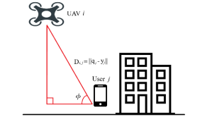
NLoS paths may experience higher path loss as compared to LoS connections. We use the widely accepted air-to-ground path-loss model in [18] to characterize the path-loss between UAVs and ground users. The path loss between a UAV and user can be expressed as:
| (2) |
where is the distance between the UAV and ground user, i.e., , , denotes the speed of light, is the carrier frequency, and is the path-loss exponent. The first term in (2) represents the free-space path-loss, while and are the additional average losses for LoS and NLoS paths respectively.
II-B Quality of Service (QoS)
To quantify the QoS of ground users, we use the Shannon capacity based on the signal-to-interference-plus-noise ratio (SINR). The downlink SINR of UAV connecting to user can be expressed as:
| (3) |
with . is the received signal power by the user and is the transmission power of the UAVs. is interference power from other UAVs using the same channel , and is the thermal noise power. and are all in the units of mW. Consequently, the achieved data rate of UAV connecting to user , denoted by can be written as follows:
| (4) |
where is the available channel bandwidth. Since user is always connected by its closest UAV, we subsequently drop the subscript for brevity of notation and use to denote the QoS achieved by user while served by its associated UAV.
II-C Problem Formulation
The objective of the proposed framework is to determine a set of positions at each time instant that minimizes the difference between achieved QoS, and target QoS, for all users , while ensuring that the spatial interval of UAVs to be between the minimum safe distance and the maximum communication range . This optimization problem can be formulated as follows:
| (5) |
| s.t. | (6) | |||
In problem , we have a set of facilities (UAV ) and a set of clients (users ). Each user has a demand of target data rate and is served by one UAV. The constraints in (6) signify that the Euclidean distance between any pair of UAV and its connected user, i.e., , should be less than the maximum communication range of the UAVs. In addition, the Euclidean distance between UAVs, i.e., , should also in the the range of to avoid collision and ensure connectivity. This problem is a special case of the classical capacitated facility location problem (CFLP) which is known to be NP-hard [19]. Therefore, the problem P0 is also an NP-hard problem and we need to resort to heuristic approaches to obtain acceptable solutions.
III Methodology
In this section, we use a dynamic and distributed approach to solve the optimization problem described by P0. The UAV network is orchestrated in real-time according to the QoS needs of the users through a controller-based UAV swarming approach, which autonomously creates a resilient configuration and leverages channel switching to provide customized service to both regular and premium users. We use the widely accepted kinematic model in robotics and control literature to describe the dynamics of the UAVs as , and , where is the control input, and . For the UAVs to organize themselves in a distributed manner, the control input is designed as a linear combination of the following three terms:
| (7) |
where is an inter-UAV attractive/repulsive term, is a velocity consensus term, is a term defining the individual goal of each UAV. In order to create smooth incentive functions with finite cut-offs, we leverage the bump function in [20] and -norm in [21]. The bump function is defined as follows:
| (8) |
where and the -norm is defined as , where is a positive constant. The gradient of the -norm can be expressed as . We make use of these function to create incentives for the UAVs to achieve the optimal solution to P0. We describe each of these incentive functions along with their role in the following subsections.
III-A UAV Swarming
The swarming behavior requires UAVs to maintain a certain distance with each other and follow a group objective. This is achieved by introducing the attraction/repulsion and velocity consensus functions, which maintains the distance between UAVs through the control of their velocity. Considering the objective to enhance QoS for users, a UAV should have the tendency to approach another UAV if UAV exceeds its serving capacity. Thus, the attractive/repulsive function can be written as follows [22, 23]:
| (9) |
where is the vector from to . The function is expressed as:
| (10) |
where and to ensure that . Here, is the maximum communication range and is the minimum distance between UAVs. The velocity consensus function works as a damping force that leads to a match of movements between neighboring UAVs. The function is in the form:
| (11) |
This enforces the alignment between UAVs to increase as the distance between them decreases, until reaching the maximum value at a distance of . The velocity consensus function reduces potential collisions and disconnections between UAVs during real-time operations.
III-B QoS-Driven Dynamic Orchestration
The QoS requirements of users may vary by their subscribed services and application scenarios. We define a QoS-driven incentive function which aims to improve the received data rates of users. Based on target data rates and achieved data rates for each user connected to UAV , this term reflects the affinity of a UAV and its connected users:
| (12) | |||
The first part of the equation represents a repulsive force from users against other UAVs. If a user’s data rate requirement is not satisfied, it may generate a repulsive force against UAVs that it is not connected to for reducing interference. The second part of the equation represents an attractive force from users that are connected with UAV towards UAV . If a user’s data rate requirement is not satisfied, it may generate an attractive force to the UAV it connects with to improve link quality. Note that the parameter is selected differently for regular and premium users, i.e., .
The framework for QoS-driven dynamic placement of UAVs can be summarized using Algorithm 1. We assume each user always connect with the nearest UAV from its current position. In every iteration, UAVs compute data rates for all connected users and keep records of them. If the target data rates for a premium user is not reached and the real-time data rates have not increased during the past seconds, the UAV will switch to a free channel to reduce interference from other UAVs and therefore increase the data rates. The control input is computed using (7) and is used to update position of the UAVs. The proposed distributed algorithm has linear time complexity of for each UAV, where is the set of neighboring UAVs and is the set of all users within the communication range of the UAV.
IV Simulation Results
In this section, we simulate different UAV network scenarios and validate the efficacy of our proposed algorithm. Unless otherwise specified, the model parameters used in the simulations are provided as follows: the height of all UAVs, m ; the minimum distance between UAVs, m; the maximum communication range of UAVs, m. The target data rates for premium and regular users are set to Mbps and Mbps respectively. Other parameters and their values are tabulated in Table 1.
| Parameter | Notation | Value |
| UAV carrier frequency | 2 GHz | |
| LoS additional avg loss | 0.1 dB | |
| NLoS additional avg loss | 21.0 dB | |
| Environment parameters | 4.88, 0.43 | |
| UAV transmission power | 37.0 dBm | |
| Bandwidth | 15 MHz | |
| Thermal Noise | 80 dBm | |
| Incentive function | 0.1, 5.0, 5.0, 80.0 | |
| parameters | 6.0, 4.0, 1.5 | |
| Channel switch interval | 5.0 sec |
IV-A QoS Driven Proactive UAV Placement
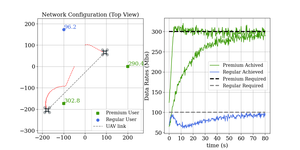
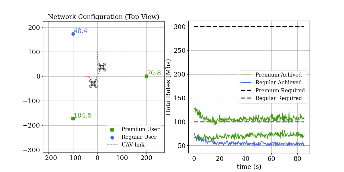
We first consider a simple scenario of three users served by two UAVs to demonstrate the operation of the proposed framework. The user locations and types are shown in Fig. 3. We consider two premium users and one regular user. UAVs are initially placed arbitrarily and the red dotted lines shows how their trajectory evolve over time to reach the final configuration. At the initial state, the premium users do not achieve the required data rates so they generate an attractive force on their connected UAVs. Hence, we observe that the two UAVs move closer to the respective premium users. However, to further enhance data rates, the UAVs need to move farther from each other to reduce interference. Therefore, one of the UAVs follows an arc trajectory around the connected user to maximize the data rates of the regular user while maintaining the already achieved data rates of the premium user. Note that the UAVs also need to ensure a minimum distance between then to enable localized backhaul connectivity. This is highlighted by the black dotted line in the figure. Simulation using standard flocking algorithm [21] alone was compared in Fig. 4. The UAVs can gather around the centroid of the three users and maintain the minimum distance with each other. However, they cannot adapt their positions according to the QoS needs and resulted in unsatisfied data rates.
IV-B Resilience under Failures and Attacks
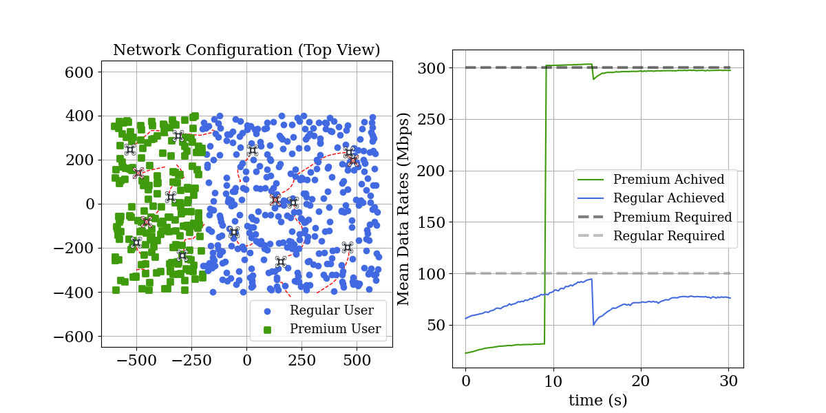
In Fig. 5, we consider the scenario of 600 users located in a rectangular region mimicking a parade or a procession. The users are placed randomly according to a uniform distribution and are split into two types. We assume that 30% of the users are premium users and are located in the left part highlighted by green dots. The regular users are located on the right side and highlighted in blue. 15 UAVs are deployed to provide service to the users. The initial positions and traces of the UAVs are shown by dotted red lines in Fig. 5. Due to the signal interference and geographical distance, the premium users gain low data rates in the initial state. At time s, the data rates of premium users reach a bottleneck so UAVs which serve premium users switch their channels because the premium users cannot meet their QoS requirements. Seven UAVs change to serve premium users only and the other three UAVs serve the regular users. As the interference is eliminated, the mean data rates for premium users goes up to the desired 300 Mbps at time s. To test the resilience of the network, 30% of UAVs randomly fail at t=15s. Failed UAVs are labeled with red cross. The UAVs rapidly reconfigure their formation and recover the QoS. At t=30s, the mean data rates for premium users recover to over 293 Mbps and the data rates for regular users recover to over 79 Mbps.
IV-C Network Size and Impact on QoS Provisioning
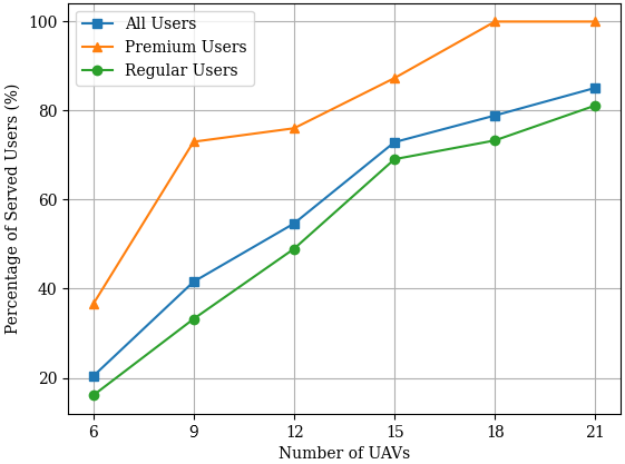
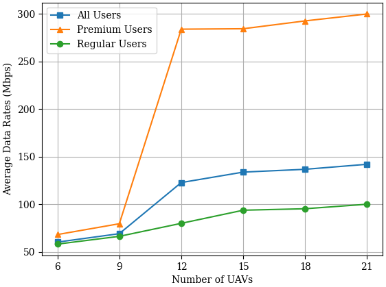
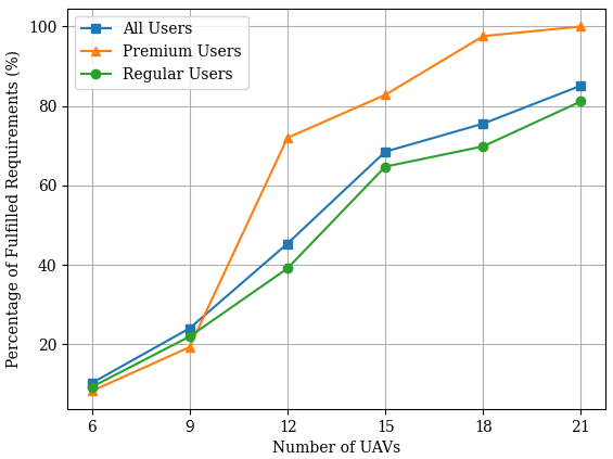
Next, we investigate the impact of changing the number of UAV BSs on the the achieved performance of the ground users. We use the scenario illustrated in Fig. 5 and increase the number of UAVs to observe the number of served users and achieved data rates as compared to the targets of both premium and regular users. Fig. 6(a), 6(b), and 6(c) respectively show the percentage of served users, average data rates, and percentage of fulfilled data requirements for different user groups against the number of UAVs. When only 6 UAVs are available, the UAVs can only serve a small proportion of the total users due to capacity constraints and can be far away from users that are located at the edges. So the percentage of served users and the average data rates are low. As the number of UAVs increases to 21, the QoS of the network improves until all the premium users are served and achieve the required data rates. It can be shown that the QoS of the network makes fast improvements at initial states before converging to their maximum values as the number of UAVs increases until reaching the capacity limit of the UAV network. Note that the premium users achieve higher performance not only in terms of the target data rates but also in the percentage of served users and the percentage of fulfilled requirements. The only exception to this is observed in Fig. 6(c) for small number of UAVs since the target data rates of premium users are too aggressive and could not be achieved by a small number of UAVs. However, with large number of UAVs, both the primary users and regular users are able to completely achieve their targets.
V Conclusions
In this paper, we investigated the design of QoS-centric dynamic placement of UAVs to provide customized service quality for different user requirements. We leveraged the mobility and flexibility of aerial placement in UAVs and developed on-demand UAV small cell deployment strategies to not only provide higher data rates to users in required regions but also provide service differentiation for meeting users needs (live streaming, social media activities) and also higher revenues for service providers. The proposed method utilized distributed UAV flocking and swarming dynamics, and extended it by adding an incentive function based on target and real-time data rates. Compared with open-loop optimization approaches, the QoS-driven dynamic placement algorithm has linear time complexity and provides adaptive coverage and differentiated service levels. The simulation results show that our proposed method is able to fulfill the data rates requirements of premium and regular users in both simple and complex scenarios. The proposed solution can be useful in real networks where fixed small cell deployment may be economically in-viable for occasional needs for high speed connectivity.
References
- [1] Y. Wang and J. Farooq, “Resilient UAV formation for coverage and connectivity of spatially dispersed users,” in IEEE International Conference on Communications (ICC 2022), Seoul, South Korea, May 2022.
- [2] “Integration of civil unmanned aircraft systems (UAS) in the national airspace system (NAS) roadmap,” Federal Aviation Administration, Tech. Rep., 3rd Edition, Rep. no. AUS-200807-002, 2020.
- [3] K. G. Panda, S. Das, and D. Sen, “Efficient UAV placement strategy for guaranteed QoS demand,” in IEEE 92nd Vehicular Technology Conference (VTC-Fall 2020), Victoria, BC, Canada, Dec. 2020.
- [4] Y. Zeng, Q. Wu, and R. Zhang, “Accessing from the sky: A tutorial on UAV communications for 5G and beyond,” Proceedings of the IEEE, vol. 107, no. 12, 2019.
- [5] C. Zhang, L. Zhang, L. Zhu, T. Zhang, Z. Xiao, and X.-G. Xia, “3D deployment of multiple UAV-mounted base stations for UAV communications,” IEEE Transactions on Communications, vol. 69, no. 4, 2021.
- [6] S. Zhang and W. Cheng, “Statistical QoS provisioning for UAV-enabled emergency communication networks,” in IEEE Globecom Workshops (GC Wkshps 2019), Big Island, HI, USA, Dec. 2019.
- [7] J. Luo, J. Song, F. Zheng, L. Gao, and T. Wang, “User-centric UAV deployment and content placement in cache-enabled multi-UAV networks,” IEEE Transactions on Vehicular Technology, pp. 1–1, 2022.
- [8] H. R. Chi and A. Radwan, “An overview of on-demand deployment optimization of small cells,” IEEE Network, vol. 35, no. 2, 2021.
- [9] H. Niu, X. Zhao, and J. Li, “3D location and resource allocation optimization for UAV-enabled emergency networks under statistical QoS constraint,” IEEE Access, vol. 9, 2021.
- [10] X. Zhang, J. Wang, and H. V. Poor, “Statistical delay and error-rate bounded QoS provisioning for 6G mURLLC over AoI-driven and UAV-enabled wireless networks,” in IEEE Conference on Computer Communications (INFOCOM 2021), 2021, pp. 1–10.
- [11] Y. Huang, M. Cui, G. Zhang, and W. Chen, “Bandwidth, power and trajectory optimization for UAV base station networks with backhaul and user QoS constraints,” IEEE Access, vol. 8, 2020.
- [12] L. Shi and S. Xu, “UAV path planning with QoS constraint in device-to-device 5G networks using particle swarm optimization,” IEEE Access, vol. 8, 2020.
- [13] J. Qin, Z. Wei, C. Qiu, and Z. Feng, “Edge-prior placement algorithm for UAV-mounted base stations,” in IEEE Wireless Communications and Networking Conference (WCNC 2019), 2019, pp. 1–6.
- [14] N. Nouri, J. Abouei, A. R. Sepasian, M. Jaseemuddin, A. Anpalagan, and K. N. Plataniotis, “Three-dimensional multi-UAV placement and resource allocation for energy-efficient IoT communication,” IEEE Internet of Things Journal, vol. 9, no. 3, pp. 2134–2152, 2022.
- [15] R. Chen, Y. Sun, L. Liang, and W. Cheng, “Joint power allocation and placement scheme for UAV-assisted IoT with QoS guarantee,” IEEE Transactions on Vehicular Technology, vol. 71, no. 1, pp. 1066–1071, 2022.
- [16] M. Alzenad, A. El-Keyi, F. Lagum, and H. Yanikomeroglu, “3-D placement of an unmanned aerial vehicle base station (UAV-BS) for energy-efficient maximal coverage,” IEEE Wireless Communications Letters, vol. 6, no. 4, pp. 434–437, 2017.
- [17] V. Saxena, J. Jaldén, and H. Klessig, “Optimal UAV base station trajectories using flow-level models for reinforcement learning,” IEEE Transactions on Cognitive Communications and Networking, vol. 5, no. 4, pp. 1101–1112, 2019.
- [18] A. Al-Hourani, S. Kandeepan, and S. Lardner, “Optimal LAP altitude for maximum coverage,” IEEE Wireless Communications Letters, vol. 3, no. 6, pp. 569–572, 2014.
- [19] L.-Y. Wu, X.-S. Zhang, and J.-L. Zhang, “Capacitated facility location problem with general setup cost,” Computers & Operations Research, vol. 33, no. 5, 2006.
- [20] R. Saber and R. Murray, “Flocking with obstacle avoidance: cooperation with limited communication in mobile networks,” in 42nd IEEE International Conference on Decision and Control (CDC 2003), Maui, HI, USA 2003.
- [21] R. Olfati-Saber, “Flocking for multi-agent dynamic systems: Algorithms and theory,” IEEE Transactions on Automatic Control, vol. 51, no. 3, 2006.
- [22] M. J. Farooq and Q. Zhu, “A multi-layer feedback system approach to resilient connectivity of remotely deployed mobile Internet of things,” IEEE Transactions on Cognitive Communications and Networking, vol. 4, no. 2, pp. 422–432, 2018.
- [23] ——, “Cognitive connectivity resilience in multi-layer remotely deployed mobile internet of things,” in GLOBECOM 2017 - 2017 IEEE Global Communications Conference, 2017, pp. 1–6.