Quantum Information Approach to the Implementation of a Neutron Cavity
Abstract
Using the quantum information model of dynamical diffraction we consider a neutron cavity composed of two perfect crystal silicon blades capable of containing the neutron wavefunction. We show that the internal confinement of the neutrons through Bragg diffraction can be modelled by a quantum random walk. Good agreement is found between the simulation and the experimental implementation. Analysis of the standing neutron waves is presented in regards to the crystal geometry and parameters; and the conditions required for well-defined bounces are derived. The presented results enable new approaches to studying the setups utilizing neutron confinement, such as the experiments to measure neutron magnetic and electric dipole moments.
pacs:
Valid PACS appear hereI Introduction
The advancement of silicon fabrication techniques in the 20th century has enabled the use of perfect crystals in neutron science to resolve dynamical diffraction effects. The most successful application was perfect-crystal neutron interferometry where three well-polished blades from a single ingot of silicon achieve centimeter-scale path separation and coherent superposition Rauch et al. (1974); Klepp et al. (2014); Rauch and Werner (2015); Pushin et al. (2015); Huber et al. (2019). Hallmark experiments with a perfect-crystal neutron interferometer (NI) include the first demonstration of gravity on a quantum particle Colella et al. (1975), probing of dark energy/fifth forces Lemmel et al. (2015); Li et al. (2016), observing the 4 symmetry of spinor rotation Rauch et al. (1975), and observing neutron orbital angular momentum Clark et al. (2015); Sarenac et al. (2016).
The theory of dynamical diffraction (DD) models the neutron propagation through perfect crystals. Albeit powerful, it becomes impractical when considering complicated geometries. For example, neutron cavities that employ DD have been experimentally investigated for use as a neutron storage device Jericha et al. (1996, 1997, 2000); Jaekel et al. (2005, 2005); Rauch (2001); Facchi et al. (2003). However, in-depth modelling of the neutron propagation through the cavity and parameter analysis is lacking.
The recently introduced quantum information (QI) model of DD attempts to simplify the mathematics by treating the neutron propagation as a quantum random walk Nsofini et al. (2016, 2019, 2017); Nahman-Lévesque et al. (2022). Good agreement has been found between the model and the standard DD effects such as the Borrmann triangle, pendellösung oscillations, and the spatial intensity profiles of the NI paths.
Here we apply the QI model of DD to the case of a neutron cavity built from two perfect crystal silicon blades. We show that such an arrangement can contain the neutron wavefunction. The behaviour of the neutron modes inside the cavity is characterized with respect to the cavity geometry, and good agreement is found between an initial experimental implementation and the model. In addition to providing new insights into neutron storage devices, the presented work lays the foundation for simulating the proposed measurements of the neutron magnetic and electric dipole moment Dombeck et al. (2001); Gentile et al. (2019).
II QI model for dynamical diffraction
When considering neutron diffraction through crystals, DD effects must be considered. However, the standard theory of DD is limited to idealized perfect crystals (no impurities or defects) and practically limited to simple geometries. In Nsofini et al. (2016), it was demonstrated that there exists a simpler, more computationally accessible QI based model in terms of a quantum random walk. In the QI model, the crystal is represented as a lattice of nodes which act as a unitary operator on the neutron state by either transmitting or reflecting it to its nearest neighbours. The neutron input state to every node is given by a two-state vector:
| (1) |
where and are the states propagating onto the node in the up and down directions, respectively. The action of one node is given by:
| (2) |
with coefficients
| (3) |
The parameter controls the amplitude of reflection/transmission at each node, while and are phase parameters.
The full state vector at every layer of a simulation of height is represented by a size column vector, where the entries are the up and down inputs to node number . Every lattice column has a corresponding unitary operator , and the state vector after layers is given by
| (4) |
In Nahman-Lévesque et al. (2022), it was shown that there is an equivalence between the simulation parameters and a given experimental configuration in both the Laue and Bragg geometry, given by
| (5) |
where is the number of simulation layers needed to simulate a real-space distance with parameter . is the pendellösung period inside the crystal, and is given by
| (6) |
where is the volume of a crystal unit cell, is the Bragg angle, is the neutron wavelength and is the crystal structure factor. For a material such as silicon, with common wavelengths used in experiments, is on the order of m.
III Modelling of a Neutron Cavity
Dynamic diffraction theory predicts that in the Bragg geometry, neutrons falling within a narrow range of momentum centered around the Bragg condition (the Darwin width) are reflected with close to 100% probability. In a neutron cavity composed of two perfect crystals, neutrons outside the Darwin width will escape through the crystals within the first few bounces. Conversely, neutrons inside this width are effectively confined, allowing for a great number of bounces. Interestingly, the QI model predicts that this result can be explained purely as a consequence of a quantum random walk: the total neutron wavefunction is expressed as a sum over all the possible paths through the Bragg lattice. The difference in phase accumulated by the different paths results in constructive interference only for the paths which stay confined in a small region close to the gap.
To model such a geometry, we use a single column matrix where the nodes outside (inside) the crystals are free space (Bragg diffracting) operators. The operator for the free space nodes is given by the matrix
| (7) |
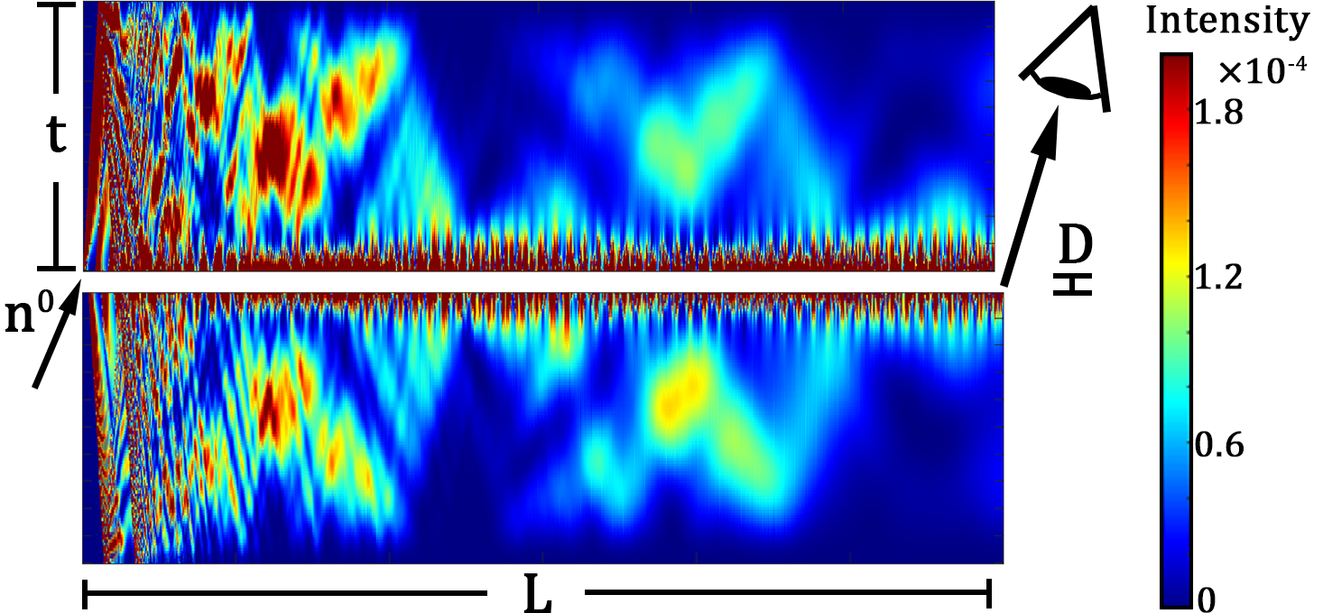
while the operator for the Bragg diffracting nodes are given by Eqn. 2. As shown in Fig. 1, without any information about transverse momentum, boundary conditions, or incident angle, the model predicts that only after a few bounces, the intensity is almost entirely localized in a narrow band around the inter-crystal gap. Most neutrons that do not settle within this band are either transmitted straight through the top of the crystal interferometer, or bounce at most once and transmit through the bottom.
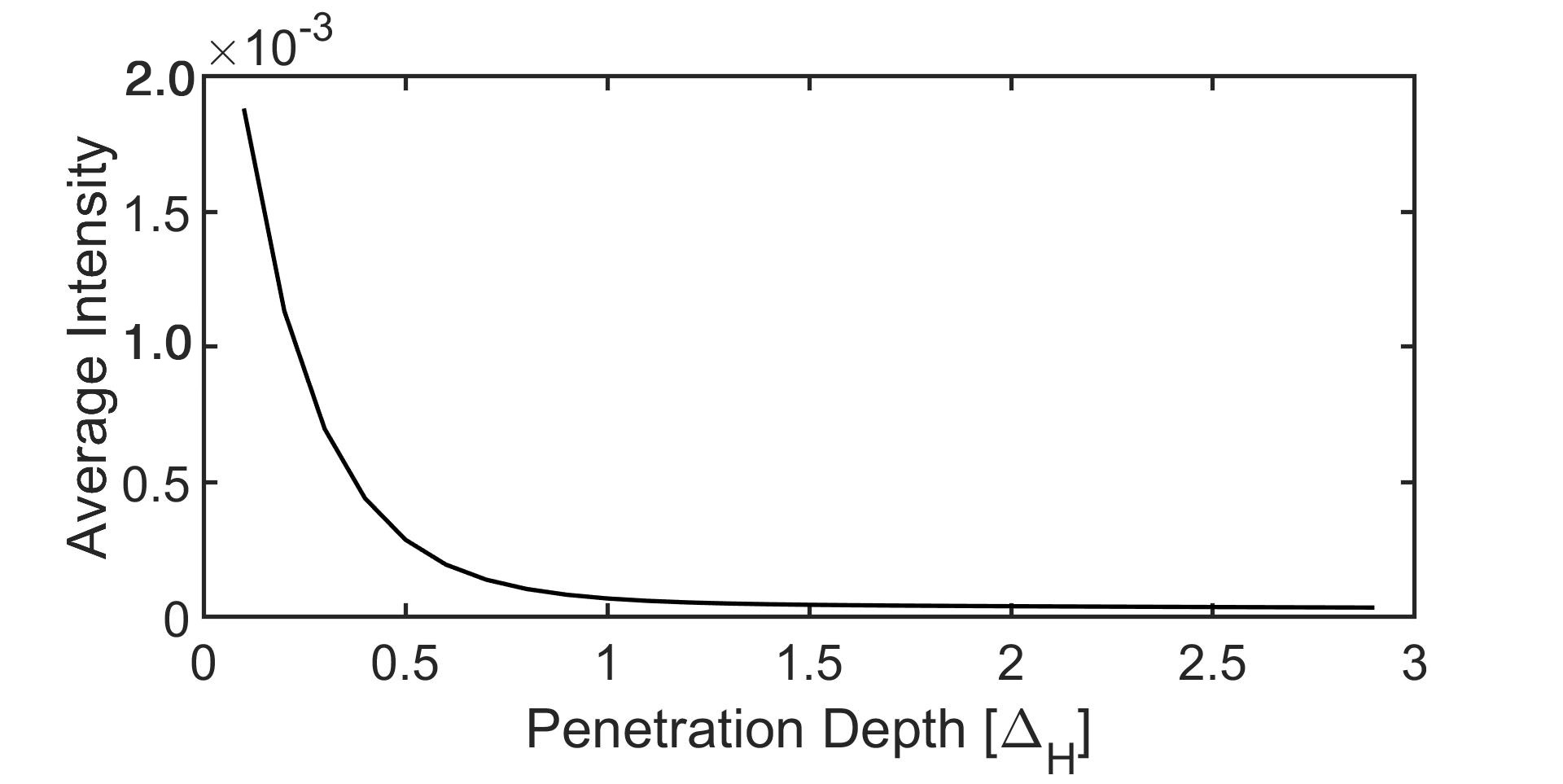
Shown in Fig. 2 is the neutron average intensity across a horizontal slice of the top crystal as a function of penetration depth into the top crystal. The intensity drops sharply within the first , showing that the confined neutrons do not penetrate very deeply inside the crystal.
III.1 Confined Intensity
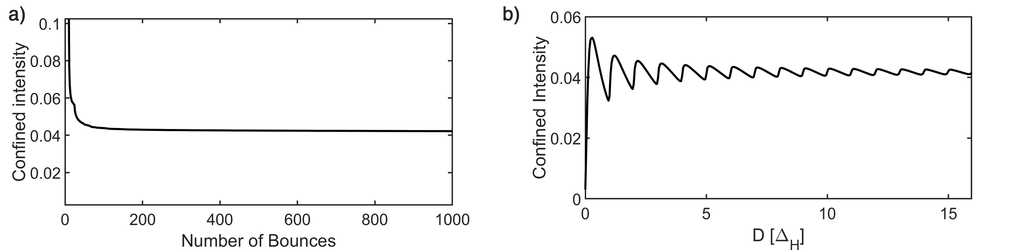
With the QI model we can examine the neutrons which remain confined within the cavity. Fig. 3 a) shows the confined intensity inside the cavity as a function of the number of bounces, for cavity parameters and . It is to be noted that as the neutron progresses through the cavity, the individual bounces become hard to resolve, and therefore here we are considering a length of crystal corresponding to a geometrical path of 1000 bounces. The intensity drops sharply as the direct beam transmits straight through the first crystal, and then drops slightly less at each subsequent reflection. Eventually, it settles to an effectively constant value of around of the incoming intensity. An estimation for the reflectivity of the crystal as the number of bounces increases can be extracted from this curve, by fitting it to an inverse exponential. The reflectivity in the “stable” region between 500 and 800 bounces is found to be .
In Fig. 3b, the intensity remaining in the cavity after a length is plotted as a function of . The confined intensity oscillates with period . The QI model indicates that to maximize the number of bounces for a given set of crystals, the spacing can be made very small without losing much intensity at the exit, but should be made no smaller than .
III.2 Cavity Modes
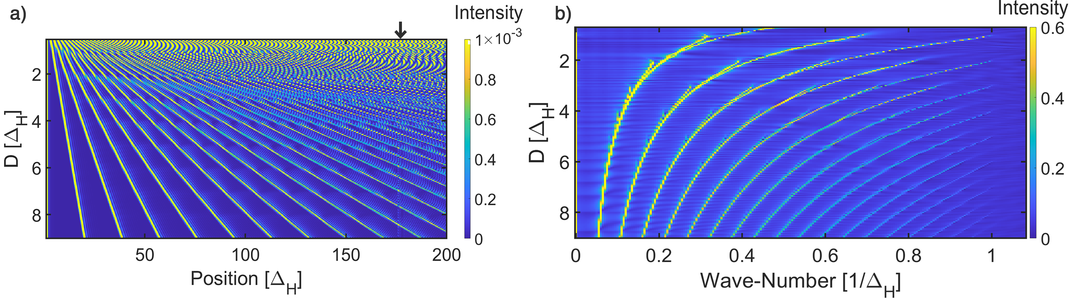
Simulation of the neutron cavity using the QI model shows that the neutrons inside the cavity settle in one of two regimes, depending on the intercrystal distance . It should be noted that in the limit where , the system reduces to a simple Laue crystal of thickness , in which case the neutron will diverge to the edges of the Bormann triangle as predicted by DD theory. However, for nonzero spacing, after the first few bounces, most of the neutron current is confined within a small band of size of order on the inside surface of the cavity, and bounces back and forth without penetrating very deeply into the crystal. Fig. 4a shows the simulated reflected intensity on the surface of the top crystal throughout the cavity, for different values of . For the D regime, the neutron behaves like a standing wave inside the cavity, with a period dependant on . For the regime with larger values of (), the bounces are well-separated and localized at first. As the number of bounces increases, the neutron wave packets spread and induce interference effects. This behavior is shown in Fig. 4b: for small , there is one dominant frequency which changes with . As increases, more pairs of harmonics are introduced.
IV Experimental Implementation
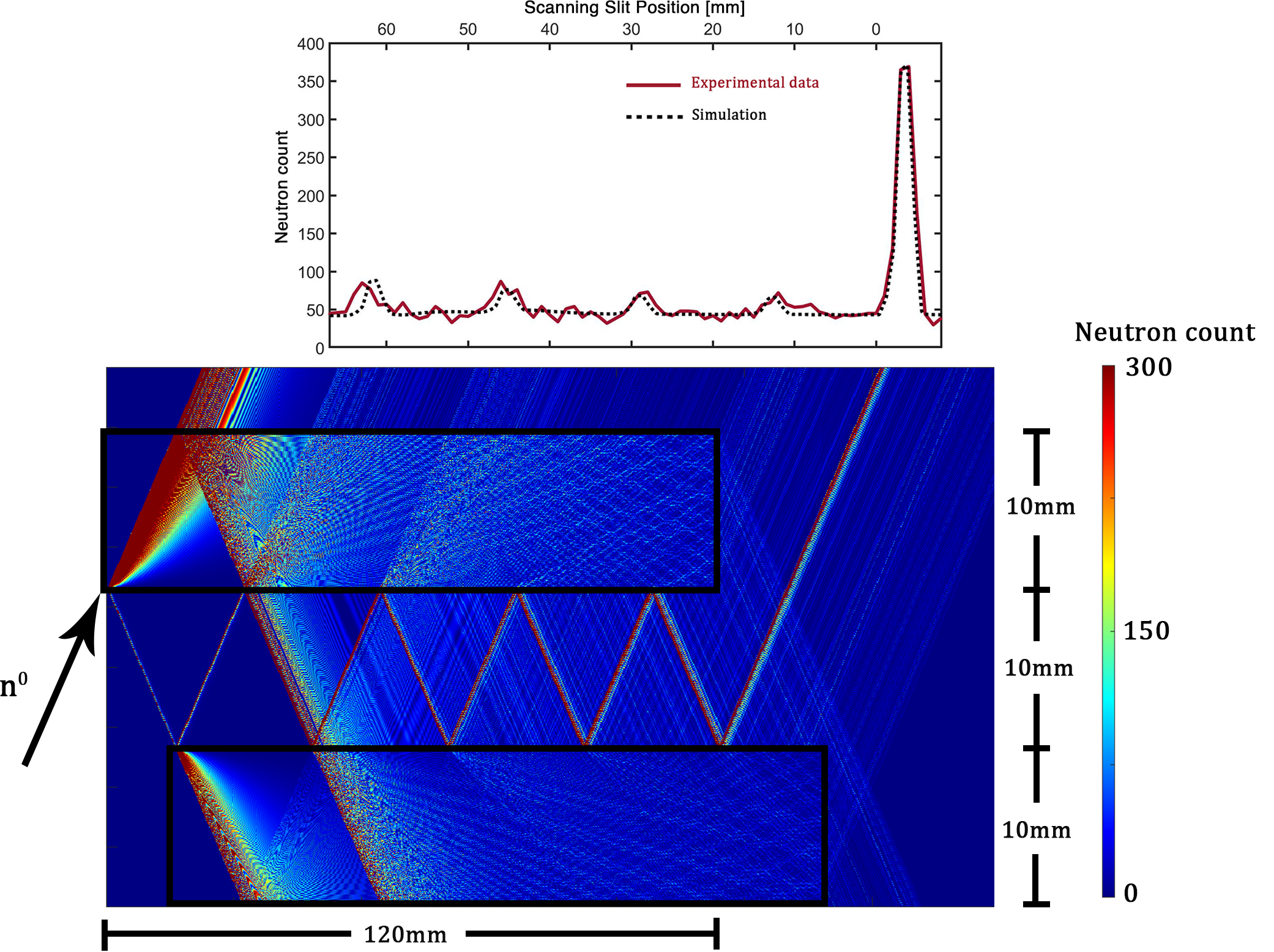
An experimental implementation of a neutron cavity was performed at the NIOF beamline at the National Institute of Standards and Technology (NIST) center for neutron research (NCNR). The setup is shown in Fig. 5. A beam of neutrons with wavelength 0.235 nm was propagated through a 10 mm wide silicon neutron cavity composed of two 10 mm thick perfect-crystal silicon blades (220 reflection) attached to a common base. The theoretical pendellösung length for this configuration is found to be m. The neutrons underwent four well-defined bounces before leaving the cavity at the exit. A scanning slit and an integrating detector were placed behind the top crystal, and were used to map the spatial intensity of neutrons along the crystal cavity.
Using the QI model we can simulate the experimental configuration. The simulation parameters were chosen according to the equivalence relation of Eq. 5. As shown in Ref. Nahman-Lévesque et al. (2022) we can account for the experimental factors such as the spread of the incident beam, beam divergence, and slit size through the analysis of a Bragg diffraction peak. Similar to the methods of Ref. Nahman-Lévesque et al. (2022) the intensity penetrating through the top crystal was convolved with the measured shape of the exit peak. The simulated intensity throughout the setup is shown as a false-color map, and the simulated integrated intensity at the detector is shown above the setup in a black, dashed line. The simulated intensity profile is in good agreement with the measured intensity profile. It can be observed that the majority of the contribution to the exiting beam of the cavity comes from the classical bouncing path.
V Conclusion and Discussion
In conclusion, we have applied the QI model of dynamical diffraction to the case of a neutron cavity composed of two perfect crystal silicon blades. The model enables us to study the dependence of the cavity modes on the system geometry. Full analysis is provided and good agreement is found between an experimental implementation and the simulation of the particular setup.
Several exciting applications and proposed measurements rely on neutron confinement inside such cavities. Our work presents an in-depth analysis of the neutron behaviour inside the crystal blades and the crystal spacing. Therefore, we expect that the QI model will become a standard and easily-accessible tool used for experimental analysis that relies on neutron dynamical diffraction.
VI Acknowledgements
This work was supported by the Canadian Excellence Research Chairs (CERC) program, the Natural Sciences and Engineering Research Council of Canada (NSERC) Discovery program, the Collaborative Research and Training Experience (CREATE) program, the Canada First Research Excellence Fund (CFREF), and the US Department of Energy, Office of Nuclear Physics, under Interagency Agreement 89243019SSC000025. The authors would like to thank Ansel Himmer and Tim Olsen for helping collect the experimental data.
References
- Rauch et al. (1974) H Rauch, W Treimer, and U Bonse, “Test of a single crystal neutron interferometer,” Phys. Lett. A 47, 369–371 (1974).
- Klepp et al. (2014) J. Klepp, S. Sponar, and Y. Hasegawa, “Fundamental phenomena of quantum mechanics explored with neutron interferometers,” Progress of Theoretical and Experimental Physics 2014, 82A01–0 (2014).
- Rauch and Werner (2015) Helmut Rauch and Samuel A Werner, Neutron interferometry: lessons in experimental quantum mechanics (Oxford University Press, New York, 2015).
- Pushin et al. (2015) DA Pushin, MG Huber, M Arif, CB Shahi, J Nsofini, CJ Wood, D Sarenac, and DG Cory, “Neutron interferometry at the national institute of standards and technology,” Advances in High Energy Physics 2015 (2015).
- Huber et al. (2019) Michael G Huber, Shannon F Hoogerheide, Muhammad Arif, Robert W Haun, Fred E Wietfeldt, Timothy C Black, Chandra B Shahi, Benjamin Heacock, Albert R Young, Ivar AJ Taminiau, et al., “Overview of neutron interferometry at nist,” in EPJ Web of Conferences, Vol. 219 (EDP Sciences, 2019) p. 06001.
- Colella et al. (1975) R. Colella, A. W. Overhauser, and S. A. Werner, “Observation of Gravitationally Induced Quantum Interference,” Phys. Rev. Lett. 34, 1472–1474 (1975).
- Lemmel et al. (2015) H Lemmel, Ph Brax, AN Ivanov, T Jenke, G Pignol, M Pitschmann, T Potocar, M Wellenzohn, M Zawisky, and H Abele, “Neutron interferometry constrains dark energy chameleon fields,” Physics Letters B 743, 310–314 (2015).
- Li et al. (2016) Ke Li, Muhammad Arif, David G Cory, Robert Haun, Benjamin Heacock, Michael G Huber, Joachim Nsofini, Dimitry A Pushin, Parminder Saggu, Dusan Sarenac, et al., “Neutron limit on the strongly-coupled chameleon field,” Physical Review D 93, 062001 (2016).
- Rauch et al. (1975) Helmut Rauch, Anton Zeilinger, Gerald Badurek, A Wilfing, W Bauspiess, and U Bonse, “Verification of coherent spinor rotation of fermions,” Physics Letters A 54, 425–427 (1975).
- Clark et al. (2015) Charles W Clark, Roman Barankov, Michael G Huber, Muhammad Arif, David G Cory, and Dmitry A Pushin, “Controlling neutron orbital angular momentum,” Nature 525, 504–506 (2015).
- Sarenac et al. (2016) Dusan Sarenac, Michael G Huber, Benjamin Heacock, Muhammad Arif, Charles W Clark, David G Cory, Chandra B Shahi, and Dmitry A Pushin, “Holography with a neutron interferometer,” Optics express 24, 22528–22535 (2016).
- Jericha et al. (1996) E Jericha, CJ Carlile, and H Rauch, “Performance of an improved perfect crystal neutron storage cavity,” Nuclear Instruments and Methods in Physics Research Section A: Accelerators, Spectrometers, Detectors and Associated Equipment 379, 330–334 (1996).
- Jericha et al. (1997) E Jericha, CJ Carlile, M Jaekel, and H Rauch, “Cold neutron storage by perfect crystals,” Physica B: Condensed Matter 234, 1066–1067 (1997).
- Jericha et al. (2000) E Jericha, DE Schwab, MR Jäkel, CJ Carlile, and H Rauch, “Neutron beam tailoring by accumulation between perfect crystal mirrors,” Physica B: Condensed Matter 283, 414–417 (2000).
- Jaekel et al. (2005) Martin R Jaekel, Erwin Jericha, and Helmut Rauch, “New developments in cold neutron storage with perfect crystals,” Nuclear Instruments and Methods in Physics Research Section A: Accelerators, Spectrometers, Detectors and Associated Equipment 539, 335–344 (2005).
- Rauch (2001) H Rauch, “Quantum zeno-effect with polarized neutrons,” Physica B: Condensed Matter 297, 299–302 (2001).
- Facchi et al. (2003) Paolo Facchi, Yoichi Nakaguro, Hiromichi Nakazato, Saverio Pascazio, Makoto Unoki, and Kazuya Yuasa, “Optimization of a neutron-spin test of the quantum zeno effect,” Physical Review A 68, 012107 (2003).
- Nsofini et al. (2016) J. Nsofini, K. Ghofrani, D. Sarenac, D. G. Cory, and D. A. Pushin, “Quantum-information approach to dynamical diffraction theory,” Physical Review A 94 (2016), 10.1103/physreva.94.062311.
- Nsofini et al. (2019) J Nsofini, D Sarenac, DG Cory, and DA Pushin, “Coherence optimization in neutron interferometry through defocusing,” Physical Review A 99, 043614 (2019).
- Nsofini et al. (2017) Joachim Nsofini, Dusan Sarenac, Kamyar Ghofrani, Michael G Huber, Muhammad Arif, David G Cory, and Dmitry A Pushin, “Noise refocusing in a five-blade neutron interferometer,” Journal of Applied Physics 122, 054501 (2017).
- Nahman-Lévesque et al. (2022) O Nahman-Lévesque, D Sarenac, DG Cory, B Heacock, MG Huber, and DA Pushin, “Generalizing the quantum information model for dynamic diffraction,” Physical Review A 105, 022403 (2022).
- Dombeck et al. (2001) T Dombeck, R Ringo, DD Koetke, H Kaiser, K Schoen, SA Werner, and D Dombeck, “Measurement of the neutron reflectivity for bragg reflections off a perfect silicon crystal,” Physical Review A 64, 053607 (2001).
- Gentile et al. (2019) TR Gentile, MG Huber, DD Koetke, M Peshkin, M Arif, T Dombeck, DS Hussey, DL Jacobson, P Nord, DA Pushin, et al., “Direct observation of neutron spin rotation in bragg scattering due to the spin-orbit interaction in silicon,” Physical Review C 100, 034005 (2019).