Transmon qubit readout fidelity at the threshold for quantum error correction without a quantum-limited amplifier
Abstract
High-fidelity and rapid readout of a qubit state is key to quantum computing and communication, and it is a prerequisite for quantum error correction. We present a readout scheme for superconducting qubits that combines two microwave techniques: applying a shelving technique to the qubit that effectively increases the energy-relaxation time, and a two-tone excitation of the readout resonator to distinguish among qubit populations in higher energy levels. Using a machine-learning algorithm to post-process the two-tone measurement results further improves the qubit-state assignment fidelity. We perform single-shot frequency-multiplexed qubit readout, with a readout time, and demonstrate 99.5 % assignment fidelity for two-state readout and 96.9 % for three-state readout—without using a quantum-limited amplifier.
I Introduction
With the recent demonstrations of quantum error correction [1, 2, 3, 4], superconducting circuits are one of the leading platforms towards the realization of a fault-tolerant quantum computer [5, 6, 7]. However, despite the remarkable progress, achieving fast and high-fidelity single-shot readout of the qubits’ states remains a challenge. As a comparison, while the two-qubit-gate fidelities are approaching the error threshold [8, 9, 10, 11], readout errors are typically at the level for two-state readout [12, 13, 14, 15]. Similarly, the implementation of high-fidelity single- and two-qubit gates takes between 10 and 100 ns [10, 11, 16], while a readout measurement can take from hundreds of nanoseconds to a few microseconds [12, 13, 14, 16]. Further improvement in the readout of superconducting qubits is therefore crucial to reliably cross the threshold of efficient error correction, which is estimated to be less than for the break-even point [7]. Moreover, having a fast and high-fidelity measurement scheme can boost the repetition rate for both quantum-computing and quantum-communication applications [17, 18, 19, 20, 21] and is essential for achieving fast reset protocols [22, 15].
In superconducting circuits, the state of a superconducting qubit is generally read out by detecting the dispersive frequency shift of a resonator coupled to the qubit [23]. The predominant source of error is the relaxation of the qubit from the excited () to the ground () state during the readout. On short time scales, this error grows almost linearly with the ratio between the readout time and the qubit relaxation time [12], and can be mitigated by reducing . Various high-power readout schemes have been exploited to decrease the measurement time [24, 25]. Furthermore, Purcell filters [26, 27, 28, 29] and quantum-limited or near-quantum-limited amplifiers [30, 31, 32, 33] have been implemented and, with the combination of both, a readout fidelity exceeding within has been demonstrated [12, 13].
Here we report the implementation of a novel readout scheme that boosts the state-assignment fidelity and increases the effective qubit relaxation time during readout. Our readout strategy exploits the higher energy levels of the qubit [34, 26, 35, 36, 14, 37] and introduced a two-tone probing of the resonator to enhance the readout fidelity of multiple states. We demonstrate single-shot readout fidelity up to () for two-state (three-state) discrimination within without using a quantum-limited amplifier. The techniques we present here offer significant protection against decay during readout, are straightforward to implement, and can be readily integrated in state-of-the-art quantum-computing devices.
II RESULTS
II.1 Experimental setup

The device design and fabrication is described in Ref. [38] with the circuit schematic shown in Fig. 1. The device consists of three fixed-frequency transmon qubits [39] with transition frequencies at , , and GHz for , , , respectively. Each qubit is coupled with a strength to a readout resonator of frequency , , and GHz. The three resonators are coupled with a strength to a common Purcell filter that is embedded in the readout feedline [28]. The Purcell-to-resonator coupling rates are designed to be at 60 MHz, while the qubit-resonator coupling rates are much larger, about 250 MHz. The Purcell filter is centered at GHz with a linewidth of MHz. The theoretical analysis and design details are discussed in the Supplementary Information I. The device is cooled down to 10 mK and a microwave setup is used to measure the signal transmitted through the feedline. The complete experimental setup and device parameters resulting from basic characterization are reported in the Supplementary Information II.

II.2 Exploiting higher energy levels
Typically, the qubit-excited-state decay is a major error source during readout, whose minimization requires performing the measurements in the shortest possible time [12, 13]. To further mitigate this error, we first implement a shelving scheme that exploits the higher energy levels [34, 26, 35, 36, 14, 40, 37]. The pulse scheme is shown in Fig. 2(a); a and a pulse are applied consecutively prior to the readout pulse so that the qubit population originally in the state is transferred to the state before the readout. Thus, the qubit population that was in will take a longer time to decay to as the main relaxation channel is through cascading single-photon emission down the energy ladder, illustrated in Fig. 2(b).
To quantify the possible improvement, we measure the population of the ground state as a function of time when the qubit is prepared in , , , and . The data for Qubit 2 is shown in Fig. 2(c). State preparation and measurement (SPAM) errors are mitigated by applying the inverse of the assignment matrix to the measurement results. Then, the most probable physical state is acquired with a maximum likelihood estimator [41]. We find that when the qubit is prepared in , the -state population decays during the readout by , with relaxation time , giving a significant contribution to the readout error. The duration of the readout pulse is minimized by optimizing the readout-pulse amplitude without introducing significant readout-induced mixing that deteriorates readout performance [42, 43, 44].
We calculate the population in the state with the following rate equations:
| (1) |
where is the relaxation rate from the to the state as illustrated in the level diagram of Fig. 2(b). The anharmonicity of the transmon is sufficient such that the nonsequential decay through multilevel channels is exponentially suppressed. The contribution of direct decay from to is found to be two orders of magnitude smaller than that from to [35] and is neglected in the equations. We can solve for the evolution of any -state population as a function of time when the qubit is initialized in the state, denoted as . Specifically, we first solve for and assume in the absence of any error and neglect the effect of higher-energy levels by using the initial conditions . We find:
| (2) |
where is approximately a factor of smaller than for typical transmon parameters. The second and third terms in Eq. (2) are two decaying functions with opposite signs, hence the net result is no longer purely exponential. We also solve the rate equations of the system in Eq. (1) for , when the qubit is prepared in , with the initial conditions , and find the following:
| (3) |
This equation contains a combination of exponential decays with different signs as well. The solutions are used to fit the data in Fig. 2(a), and we find excellent agreement between the data and the model.
For Qubit 2 in particular, we find that the readout error from the state is reduced from to after the application of a pulse, and to after a pulse. This is calculated by taking the difference between and in Fig. 2(a). The remaining error with the addition of a pulse is equivalent to the decay error of a qubit with s using the standard readout method. Thus, here we achieve larger than an order-of-magnitude improvement in effective during the readout. For a longer-lived qubit, the percentage of decay errors that can be suppressed with shelving continues to grow closer to unity [37]. However, other error contributions will likely become more prominent at this level.
II.3 Two-state readout with a primary tone
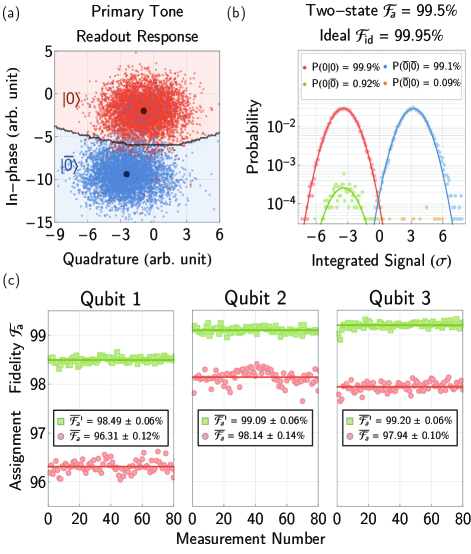
Having optimized the state-preparation pulses (see Methods section), we fine-tune the readout frequency to maximally separate the 2D in-phase and quadrature (IQ) histograms corresponding to the and states, as shown in Fig. 3(a). Higher energy levels are indistinguishable from in this configuration, and we can only distinguish between and (NOT ). To calibrate the readout, we prepare the qubit in either or and add the and pulses to transfer the -state population to the state before the readout, as illustrated in Fig. 2(a). First, we start with a single readout tone in the pulse which is referred to as the primary tone. To discard the results for which the initial state is not , we include a preselection pulse, i.e., an additional readout measurement before the sequence starts [12, 45]. Through this preselection procedure, thermal and residual populations in the qubits are filtered from the outcomes.
We perform simultaneous readout of all three qubits and calculate the single-qubit readout assignment fidelity , where is the classification probability, i.e., the probability that the state is assigned given that the state is initially prepared. This measure of readout fidelity takes all the error contributions into account, including imperfect state preparation before the readout sequence. The assignment fidelity for 80 repetitions, each containing 50,000 shots, is shown in Fig. 3(c) with () and without () implementation of the shelving technique. The data demonstrates a reduction in the overall error rate by 57 on average for the three qubits with the introduced readout scheme. We also compute the ideal readout fidelity by integrating the overlapping area of the Gaussian probability distributions after projecting the IQ data onto an optimal axis [46]:
| (4) |
where the signal-to-noise ratio is
| (5) |
with being the set of measurement outcomes and being the variance of the data set. For Qubit 2, the best assignment fidelity is while the ideal fidelity exceeds ; see Fig. 3(b) for detailed histograms. The error from qubit decay ideally no longer contributes to the remaining error, , when measuring the excited state. This suggests that the fidelity is predominantly limited by other sources of error, such as state preparation [12] and measurement-induced mixing [42, 43, 44, 47, 48].
II.4 Three-state readout with two tones
Choosing the optimal readout frequency to attain the best two-state assignment fidelity leaves other higher-energy states indistinguishable from each other. However, the information of the -state population is crucial to detect leakage errors during gate calibrations and algorithms [2]. To access this information, we introduce a secondary readout tone with the frequency that maximizes the separation between and . This pulse is multiplexed with the primary pulse to perform the readout measurements simultaneously.

We also use the and pulses to implement the shelving scheme. As the initial -level population is transferred to the state and the -population is transferred to the state, an error in -state assignment will occur if a cascade of decays happens from to . The effective relaxation time during readout is enhanced, leading to similar improvement as that discussed in Sec. II.2. To quantify the improvement, we need to solve Eq. (1) for the evolution of population . The analytical solution is
| (6) |
With the qubit being in the state (), the effective population accumulation in after a readout time of ns is . This is two orders of magnitude smaller than the error from a direct decay of the -state population with rate , corresponding to . Therefore, the contribution from energy relaxation to the three-state readout error should be reduced by a similar factor.
The secondary tone is tuned up in the presence of the primary pulse. An initial estimate for the secondary readout frequency is where the - and -state responses are maximally separated in the IQ-plane (see Methods section). We then fine-tune this frequency such that and are distinguishable from each other as well. After optimization, the two readout pulses are typically a few MHz apart and are multiplexed in a single waveform for the readout. The transmitted signal is then processed with standard multiplexed readout techniques [13]. We obtain two complex voltages after signal integration, each containing a pair of in-phase and quadrature values. Overlap errors are then filtered by comparing the results in post-processing. The response of the secondary tone when Qubit 2 is prepared in , , and , with 50,000 repetitions per state, is shown in Fig. 4(a). Since and are indistinguishable, we combine the results together and relabel them as the -state.
|
|
|
|
||||||||
|---|---|---|---|---|---|---|---|---|---|---|---|
| Overlap Error | |||||||||||
We then formulate two methods to combine the results from the primary and secondary readout pulses to reconstruct the population initially prepared in , , and . The first method is a truth table (see Table 1) that takes the individual measurement results from the two tones as a pair of input values. There exists a unique initial state that is compatible with both results. For example, if the primary result is and the secondary result is , then the initially prepared state must be . In case these two results cannot reach a common decision due to overlap error, the measurement is discarded.
The second method to discriminate the qubit state utilizes a feedforward neural network (FNN). The network was organically developed for multiplexed readout [49] and is adapted here to treat the two data sets as a single system (see Methods section). The input to the neural network combines the in-phase () and quadrature () data from the integrated signal of the two tones into a four-element vector . After being trained with a calibration data set, the neural network is able to classify two-tone results and give the initial qubit state as the output.
The resulting assignment matrix, shown in Fig. 4(b), demonstrates an assignment fidelity of for the three-state readout. This result shows a significant improvement over the average assignment fidelity that we find using only a single readout pulse at an optimal readout frequency to distinguish between , , and , with the overall error rate reduced by 47. The amount of suppression is achieved with the neural network that consistently outperforms the truth table by 13 in overall error rate reduction.
A feature of the resulting assignment matrix is that the population originally in has a higher probability to be misidentified as than as , which is due to the shelving technique. Since the initial -state population is transferred to before measurement, decaying to the ground state is more likely than the excitation back to higher energy levels.
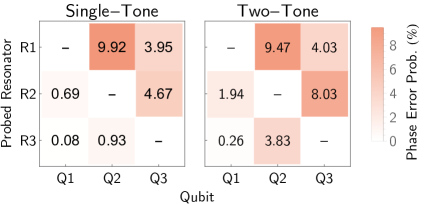
We also investigate the effect of increased photon population in the resonators due to the secondary tone. A large photon number leads to significant measurement-induced mixing and readout crosstalk that contribute to the overall readout error [13, 50]. To minimize readout errors due to measurement-induced mixing, we optimize the readout amplitude such that the critical photon number is not exceeded with the addition of the secondary tone. To investigate readout crosstalk, we determine the measurement-induced dephasing with and without the secondary tone [13]. We find that the probabilities of a phase error in untargeted qubits are a factor of three larger on average due to the increase in photon number, as shown in Fig. 5. Mitigation strategies may be required if this contribution becomes significant for error-correction algorithms.
In the design of future devices, the qubits could be grouped into physically separated readout lines depending on their designation, e.g., ancilla or data qubits, and whether their measurements occur simultaneously. Moreover, the induced crosstalk could be further mitigated with other techniques such as machine-learning algorithms for discrimination and readout pulse shaping [51, 52, 49].
III DISCUSSION
In conclusion, we have demonstrated that exploiting the higher energy levels of the qubit together with the implementation of a secondary readout tone lead to an improved readout-assignment fidelity of () for two-state (three-state) discrimination within 140 ns of readout time, reducing the overall error rate by () compared to our baseline. This result could be further improved with the use of a quantum-limited parametric amplifier. The proposed pulse scheme is straightforward to implement in any measurement sequence to improve readout fidelity.
To further develop these readout techniques, more complex methods in the construction of the primary and secondary readout tones could be explored. More sophisticated deep neural-network methods could also be employed to aid state classification of the two-tone readout results [49]. The possibility to generalize these techniques to further boost fidelity for multiplexed readout is a promising prospect for the future investigation of quantum computing with superconducting qubits.
IV METHODS
IV.1 Pulse calibration
We optimize the parameters of the and pulses similar to the standard method developed for the pulse. The pulse lengths are set to be as a starting point. We first prepare the qubit in and conduct Rabi and Ramsey-like experiments between the higher energy levels to optimize the amplitude and frequency of the respective drive pulse. For shorter pulse lengths a proper derivative removal by adiabatic gate (DRAG) [53, 54] needs to be calibrated for the and pulses as well.
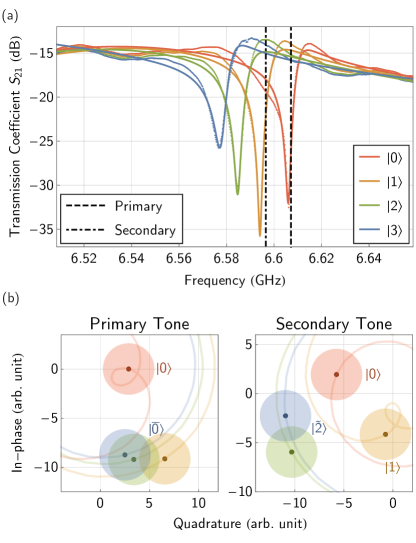
With the state-preparation pulses calibrated, we acquire the responses of the readout resonator when the qubit is prepared in , , , and , respectively, illustrated in Fig. 6(a). We plot the in-phase and quadrature parts of the spectroscopy result, as shown in Fig. 6(b). We calculate the distance between each point of a pair of trajectories, which represents the separation of the two respective state responses as a function of readout frequency. We find the readout frequencies that maximize - separation for the primary tone, and - separation for the secondary tone. As the readout tones are multiplexed into a single pulse, the frequency and phase of the secondary tone is fine-tuned to minimize the effect on the measurement performance of the primary tone. The amplitudes of both tones are adjusted together to avoid significant readout-induced mixing.
IV.2 Feedforward neural network
We utilize a feedforward neural network (FNN) with two hidden layers to discriminate the qubit state using the combined two-tone results. The choice of using an FNN over other methods such as support-vector machine (SVM) or non-linear support-vector machine (NSVM) is justified by the fact that an FNN could achieve greater performance when discriminating more than two states as well as better scalability [49]. An SVM or NSVM will also need to be retrained from scratch every time. While on the other hand, the FNN is capable of transfer learning, where retraining of the network during future re-calibration of the system is significantly more efficient [55]. The advantage of using FNN is significant enough to warrant a wider application [51, 56, 49].
The network is implemented with Wolfram Mathematica. The input layer contains four nodes corresponding to the in-phase and quadrature components of the two-tone results, , of each individual single shot measurement . The first hidden layer contains 16 nodes, while the second layer has 8 nodes. Each node consists of the hidden layers is filtered by a scaled exponential linear unit (SELU), which acts as the nonlinear activation function. Finally, the output layer contains three nodes, representing the probability of the qubit being in state , , and , respectively. We specify an epoch of 100 and learning rate of 0.0005 with a batch size of 64 as a starting point. The network is then trained with 8000 samples and validated by 2000 samples.
Data availability
All relevant data and figures supporting the main conclusions of the document are available on request. Please refer to Liangyu Chen at liangyuc@chalmers.se.
Acknowledgements
We would like to thank Daryoush Shiri for valuable discussions on microwave theory and simulation. The fabrication of our quantum processor was performed in part at Myfab Chalmers and flip-chip integration was done at VTT. We are grateful to the Quantum Device Lab at ETH Zürich for sharing their designs of printed circuit board and sample holder. The device simulations were enabled by resources provided by the Swedish National Infrastructure for Computing (SNIC) at National Supercomputer Centre (NSC) partially funded by the Swedish Research Council through grant agreement no. 2018-05973. This research was financially supported by the Knut and Alice Wallenberg Foundation through the Wallenberg Center for Quantum Technology (WACQT), the Swedish Research Council, and the EU Flagship on Quantum Technology H2020-FETFLAG-2018-03 project 820363 OpenSuperQ.
Author Contributions
L.C. performed the measurements and analysis of the results; L.C. and H.L. designed and simulated the device; L.C. and Y.L. developed the idea and carried out theoretical simulations of the system. L.C., C.W.W., and C.J.K. contributed to the implementation of the control methods. S.A. and B.L. developed the machine learning algorithm. S.K., M.R., A.O., J.Bi., A.F.R., M.C., K.G., L.G., and J.G. participated in the fabrication of the device. L.C., G.T. wrote and A.F.K., P.D., and J.By. edited the manuscript. A.F.K., P.D., J.By., and G.T. provided supervision and guidance during the project. All authors contributed to the discussions and interpretations of the results.
COMPETING INTERESTS
The authors declare no competing interests.
References
- Chen et al. [2021] Chen, Z. et al., Exponential suppression of bit or phase errors with cyclic error correction, Nature 595, 383–387 (2021).
- Krinner et al. [2022] Krinner, S. et al., Realizing repeated quantum error correction in a distance-three surface code, Nature 605, 669–674 (2022).
- Zhao et al. [2022] Zhao, Y. et al., Realization of an error-correcting surface code with superconducting qubits, Phys. Rev. Lett. 129, 030501 (2022).
- Acharya et al. [2022] Acharya, R. et al., Suppressing quantum errors by scaling a surface code logical qubit, https://arxiv.org/abs/2207.06431 (2022).
- Lo et al. [1998] Lo, H.-K., Spiller, T. & Popescu, S., Introduction to Quantum Computation and Information (World Scientific, 1998).
- Fowler et al. [2012] Fowler, A. G., Mariantoni, M., Martinis, J. M. & Cleland, A. N., Surface codes: Towards practical large-scale quantum computation, Phys. Rev. A 86, 032324 (2012).
- Martinis [2015] Martinis, J. M., Qubit metrology for building a fault-tolerant quantum computer, npj Quantum Inf. 1, 15005 (2015).
- Foxen et al. [2020] Foxen, B. et al. (Google AI Quantum), Demonstrating a continuous set of two-qubit gates for near-term quantum algorithms, Phys. Rev. Lett. 125, 120504 (2020).
- Xu et al. [2020] Xu, Y. et al., High-fidelity, high-scalability two-qubit gate scheme for superconducting qubits, Phys. Rev. Lett. 125, 240503 (2020).
- Negîrneac et al. [2021] Negîrneac, V. et al., High-fidelity controlled-Z gate with maximal intermediate leakage operating at the speed limit in a superconducting quantum processor, Phys. Rev. Lett. 126, 220502 (2021).
- Sung et al. [2021] Sung, Y. et al., Realization of high-fidelity CZ and ZZ-free iSWAP gates with a tunable coupler, Phys. Rev. X 11, 021058 (2021).
- Walter et al. [2017] Walter, T. et al., Rapid high-fidelity single-shot dispersive readout of superconducting qubits, Phys. Rev. Appl. 7, 054020 (2017).
- Heinsoo et al. [2018] Heinsoo, J. et al., Rapid high-fidelity multiplexed readout of superconducting qubits, Phys. Rev. Appl. 10, 034040 (2018).
- Elder et al. [2020] Elder, S. S. et al., High-fidelity measurement of qubits encoded in multilevel superconducting circuits, Phys. Rev. X 10, 011001 (2020).
- Sunada et al. [2022] Sunada, Y. et al., Fast readout and reset of a superconducting qubit coupled to a resonator with an intrinsic Purcell filter, Phys. Rev. Appl. 17, 044016 (2022).
- Blais et al. [2021] Blais, A., Grimsmo, A. L., Girvin, S. M. & Wallraff, A., Circuit quantum electrodynamics, Rev. Mod. Phys. 93, 025005 (2021).
- Campagne-Ibarcq et al. [2018] Campagne-Ibarcq, P. et al., Deterministic remote entanglement of superconducting circuits through microwave two-photon transitions, Phys. Rev. Lett. 120, 200501 (2018).
- Kurpiers et al. [2018] Kurpiers, P. et al., Deterministic quantum state transfer and remote entanglement using microwave photons, Nature 558, 264–267 (2018).
- Kurpiers et al. [2019] Kurpiers, P. et al., Quantum communication with time-bin encoded microwave photons, Phys. Rev. Appl. 12, 044067 (2019).
- Ilves et al. [2020] Ilves, J. et al., On-demand generation and characterization of a microwave time-bin qubit, npj Quantum Inf. 6, 34 (2020).
- Magnard et al. [2020] Magnard, P. et al., Microwave quantum link between superconducting circuits housed in spatially separated cryogenic systems, Phys. Rev. Lett. 125, 260502 (2020).
- Dassonneville et al. [2020] Dassonneville, R. et al., Fast high-fidelity quantum nondemolition qubit readout via a nonperturbative cross-kerr coupling, Phys. Rev. X 10, 011045 (2020).
- Blais et al. [2004] Blais, A., Huang, R.-S., Wallraff, A., Girvin, S. M. & Schoelkopf, R. J., Cavity quantum electrodynamics for superconducting electrical circuits: An architecture for quantum computation, Phys. Rev. A 69, 062320 (2004).
- Reed et al. [2010a] Reed, M. D. et al., High-fidelity readout in circuit quantum electrodynamics using the Jaynes-Cummings nonlinearity, Phys. Rev. Lett. 105, 173601 (2010a).
- Gusenkova et al. [2021] Gusenkova, D. et al., Quantum nondemolition dispersive readout of a superconducting artificial atom using large photon numbers, Phys. Rev. Applied 15, 064030 (2021).
- Mallet et al. [2009] Mallet, F. et al., Single-shot qubit readout in circuit quantum electrodynamics, Nat. Phys. 5, 791–795 (2009).
- Reed et al. [2010b] Reed, M. D. et al., Fast reset and suppressing spontaneous emission of a superconducting qubit, Appl. Phys. Lett. 96, 203110 (2010b).
- Jeffrey et al. [2014] Jeffrey, E. et al., Fast accurate state measurement with superconducting qubits, Phys. Rev. Lett. 112, 190504 (2014).
- Sete et al. [2015] Sete, E. A., Martinis, J. M. & Korotkov, A. N., Quantum theory of a bandpass Purcell filter for qubit readout, Phys. Rev. A 92, 012325 (2015).
- Yurke et al. [1989] Yurke, B. et al., Observation of parametric amplification and deamplification in a Josephson parametric amplifier, Phys. Rev. A 39, 2519–2533 (1989).
- Mutus et al. [2014] Mutus, J. Y. et al., Strong environmental coupling in a Josephson parametric amplifier, Appl. Phys. Lett. 104, 263513 (2014).
- Macklin et al. [2015] Macklin, C. et al., A near quantum-limited Josephson traveling-wave parametric amplifier, Science 350, 307–310 (2015).
- Renger et al. [2021] Renger, M. et al., Beyond the standard quantum limit for parametric amplification of broadband signals, npj Quantum Inf. 7, 160 (2021).
- Martinis et al. [2002] Martinis, J. M., Nam, S., Aumentado, J. & Urbina, C., Rabi oscillations in a large Josephson-junction qubit, Phys. Rev. Lett. 89, 117901 (2002).
- Peterer et al. [2015] Peterer, M. J. et al., Coherence and decay of higher energy levels of a superconducting transmon qubit, Phys. Rev. Lett. 114, 010501 (2015).
- Jurcevic et al. [2021] Jurcevic, P. et al., Demonstration of quantum volume 64 on a superconducting quantum computing system, Quantum Sci. Technol. 6, 025020 (2021).
- Wang et al. [2021] Wang, C., Chen, M.-C., Lu, C.-Y. & Pan, J.-W., Optimal readout of superconducting qubits exploiting high-level states, Fundam. Res. 1, 16–21 (2021).
- Kosen et al. [2022] Kosen, S. et al., Building blocks of a flip-chip integrated superconducting quantum processor, Quantum Sci. Technol. 7, 035018 (2022).
- Koch et al. [2007] Koch, J. et al., Charge-insensitive qubit design derived from the Cooper pair box, Phys. Rev. A 76, 042319 (2007).
- Cottet et al. [2021] Cottet, N., Xiong, H., Nguyen, L. B., Lin, Y.-H. & Manucharyan, V. E., Electron shelving of a superconducting artificial atom, Nat. Commun. 12, 6383 (2021).
- Baumgratz et al. [2013] Baumgratz, T., Nüßeler, A., Cramer, M. & Plenio, M. B., A scalable maximum likelihood method for quantum state tomography, New J. Phys. 15, 125004 (2013).
- Schuster et al. [2005] Schuster, D. I. et al., AC Stark shift and dephasing of a superconducting qubit strongly coupled to a cavity field, Phys. Rev. Lett. 94, 123602 (2005).
- Gambetta et al. [2006] Gambetta, J. et al., Qubit-photon interactions in a cavity: Measurement-induced dephasing and number splitting, Phys. Rev. A 74, 042318 (2006).
- Schuster et al. [2007] Schuster, D. I. et al., Resolving photon number states in a superconducting circuit, Nature 445, 515–518 (2007).
- Ristè et al. [2012] Ristè, D., van Leeuwen, J. G., Ku, H.-S., Lehnert, K. W. & DiCarlo, L., Initialization by measurement of a superconducting quantum bit circuit, Phys. Rev. Lett. 109, 050507 (2012).
- Magesan et al. [2015] Magesan, E., Gambetta, J. M., Córcoles, A. D. & Chow, J. M., Machine learning for discriminating quantum measurement trajectories and improving readout, Phys. Rev. Lett. 114, 200501 (2015).
- Sank et al. [2016] Sank, D. et al., Measurement-induced state transitions in a superconducting qubit: Beyond the rotating wave approximation, Phys. Rev. Lett. 117, 190503 (2016).
- Slichter et al. [2012] Slichter, D. H. et al., Measurement-induced qubit state mixing in circuit qed from up-converted dephasing noise, Phys. Rev. Lett. 109, 153601 (2012).
- Lienhard et al. [2022] Lienhard, B. et al., Deep-neural-network discrimination of multiplexed superconducting-qubit states, Phys. Rev. Applied 17, 014024 (2022).
- Bultink et al. [2018] Bultink, C. C. et al., General method for extracting the quantum efficiency of dispersive qubit readout in circuit qed, Appl. Phys. Lett. 112, 092601 (2018).
- Duan et al. [2021] Duan, P. et al., Mitigating crosstalk-induced qubit readout error with shallow-neural-network discrimination, Phys. Rev. Appl. 16, 024063 (2021).
- Lienhard [2021] Lienhard, B., Machine Learning Assisted Superconducting Qubit Readout, Ph.D. thesis, MIT (2021).
- Motzoi et al. [2009] Motzoi, F., Gambetta, J. M., Rebentrost, P. & Wilhelm, F. K., Simple pulses for elimination of leakage in weakly nonlinear qubits, Phys. Rev. Lett. 103, 110501 (2009).
- Gambetta et al. [2011] Gambetta, J. M., Motzoi, F., Merkel, S. T. & Wilhelm, F. K., Analytic control methods for high-fidelity unitary operations in a weakly nonlinear oscillator, Phys. Rev. A 83, 012308 (2011).
- Bengio [2012] Bengio, Y., Deep learning of representations for unsupervised and transfer learning, in Proceedings of ICML Workshop on Unsupervised and Transfer Learning, Proceedings of Machine Learning Research, Vol. 27, edited by Guyon, I., Dror, G., Lemaire, V., Taylor, G. & Silver, D. (PMLR, Bellevue, Washington, USA, 2012) pp. 17–36.
- Navarathna et al. [2021] Navarathna, R. et al., Neural networks for on-the-fly single-shot state classification, Appl. Phys. Lett. 119, 114003 (2021).