Measuring Lateral Capillary Forces on Floating Particles using the Moses Effect
Abstract
This study presents a novel and user-friendly technique for detecting the lateral capillary force on a floating spherical particle. The technique leverages the interplay between the capillary attracting forces, hydrostatic pressure forces, and magnetic repulsion forces. A magnetic field is applied to induce a surface curvature in the liquid, resulting in a non-uniform distribution of capillary and hydrostatic pressure forces across the particle’s surface. This leads to a stable equilibrium position of the particle at a specific distance from the magnet. The study analyzes the equilibrium position and other relevant parameters in comparison with the developed theory. Classical mechanics and intermolecular forces are applied to establish the theoretical basis for the method, modeling the behavior of the particle in response to the magnetic field, surface curvature, and hydrostatic pressure. The equilibrium position of the particle is determined by numerically solving the balance of forces equation.
I Introduction
The study of the interaction between floating particles and the forces acting upon them has been an active area of research for several decades. These forces are primarily due to interfacial interactions between the particles and the liquid interface, and are responsible for the stability, aggregation, and behavior of particles in the liquid. Several studies have been carried out to calculate these interfacial forces and their impact on the behavior of particles in liquids Nicolson (1949); Gifford and Scriven (1971); Princen (1969); Chan et al. (1981); Fortes (1982); Allain and Cloitre (1993); Danov and Kralchevsky (2010); Dixit and Homsy (2012); Kralchevsky et al. (1995); Paunov et al. (1993); Vassileva et al. (2005).
Nicolson’s 1949 paper presented an analytical expression for the capillary interaction force between floating bubbles. To derive this expression, Nicolson first calculated the deformation of the interface caused by a single bubble. Then, he calculated the interaction energy between two bubbles located at a certain distance from each other, assuming that the interface shape for both bubbles was the same. Nicolson also made simplifying assumptions that the bubbles did not tilt and that the contact angle around the contact circle remained zero. These assumptions allowed him to derive an analytical expression for the capillary force Nicolson (1949).
Gifford and Scriven Gifford and Scriven (1971) derived a solution for the capillary attraction between two infinite cylinders, but it was an approximate solution that relied on the assumption that the curvature of the interface near the cylinders was small. Under this assumption, they were able to derive an analytical expression for the interaction force between the cylinders, which is now known as the "Gifford-Scriven logarithmic term". While it is possible to obtain a solution to the complete nonlinear problem in terms of special functions such as elliptic integrals or hypergeometric functions, such solutions are often difficult to obtain and solve numerically. As a result, approximate solutions such as the one derived by Gifford and Scriven are often used in practice as they provide a good approximation to the interaction force in many cases.
Another possibility to solve the problem of the capillary interaction between parallel cylinders was demonstrated by Allain and Cloitre Allain and Cloitre (1993), who used free energy analysis. However, due to the complexity, the resulting equation can only be solved by using numerical methods. Moreover, the Young-Laplace equation linearized in bipolar coordinates can also be used to calculate the attraction force between particles Kralchevsky et al. (1992).
Wurger Würger (2006) studied a liquid interface with different principal curvatures and established that the mere presence of a spherical particle led to a deformation field of quadrupolar symmetry; the corresponding “capillary quadrupole moment” was given by the ratio of the particle size and the curvature radius.
While theoretical investigations of capillary forces between particles on fluid interfaces are common in the literature, there are relatively few studies where these forces have been investigated experimentally. Some experimental studies have been conducted to investigate the lateral force between two floating particles Dushkin et al. (1995); Velev et al. (1993, 1994). However, experimental works dedicated to investigating the lateral force on a single floating particle are even more scarce. One possibility to calculate and measure the force on a single spherical particle floating on a curved interface was suggested by Velev et al., who used a piezo-transducer balance Velev et al. (1993, 1994).
The researchers investigated a situation where a hydrophobic plate was placed at a specific distance from a floating particle, creating a surface curvature. Due to the interplay between the capillary forces acting on the particle and the gravity and buoyancy forces acting in the opposite direction, the particle reached a stable equilibrium position at a finite distance from the plate. The distance between the particle and the hydrophobic plate was then measured using a microscope.
In the study conducted by Dushkin and colleagues Dushkin et al. (1995), lateral immersion forces were measured systematically using a torsion micro-balance. Specifically, the forces were measured for three different configurations: between two vertical cylinders, between a cylinder and a sphere, and between a sphere and a vertical wall.
In this study, we present a new method for measuring the lateral capillary forces on a floating particle based on its response to a surface curvature imposed by a magnetic field. The method is sensitive, convenient, and provides a non-invasive way of measuring the intermolecular forces on the particle. The method is based on the interplay between the capillary attracting forces, the hydrostatic pressure forces, and the magnetic repulsion forces. It is shown that this interplay can lead to the appearance of a stable equilibrium position of the particle at a finite distance from the magnet. The dependence of the equilibrium position of the particle and other parameters is investigated and compared with the developed theory.
Overall, this new method represents an important advancement in the field of intermolecular forces and surface chemistry. It has the potential to impact a wide range of applications in various scientific disciplines, including material science, biophysics, and nanotechnology.
II Theoretical basis of the suggested experimental method
II.1 Introduction
The capillary force is a type of intermolecular force that arises due to the surface tension of liquids. It is responsible for the tendency of liquids to rise up narrow tubes, for example. The capillary force is also important in determining the behavior of particles in contact with liquid surfaces, and can lead to the aggregation or separation of particles based on their surface properties.
In addition to the capillary forces, the hydrostatic pressure forces on the particle can also be taken into account. The hydrostatic pressure force arises from the pressure difference between the top and bottom surfaces of the particle due to its immersion in a liquid. This force can contribute to the balance of forces acting on the particle in the presence of a magnetic field.
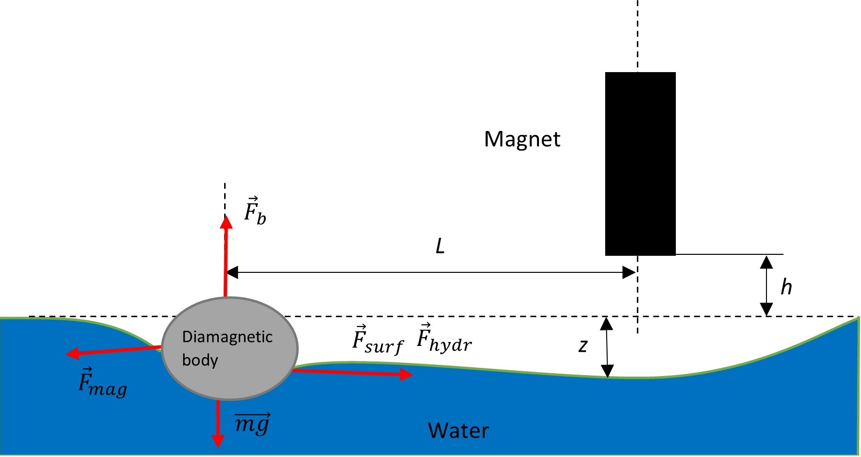
The new method for measuring the lateral capillary force on a particle is based on the interplay between the capillary attracting forces, the hydrostatic pressure forces, and the magnetic repulsion forces due to the particle’s diamagnetic properties. The magnetic field is used to impose a surface curvature of the liquid, which results in a non-uniform distribution of capillary and hydrostatic pressure forces along the surface of the particle.
As a result, the particle experiences a net force that causes it to move and ultimately reach a stable equilibrium position at a finite distance from the magnet. The balance of forces acting on the particle on the surface can be expressed mathematically as:
| (1) |
where is the capillary force acting on the particle on the surface, is the hydrostatic pressure force acting on the particle, and is the magnetic repulsion force acting on the particle.
The theoretical basis for this method involves the application of classical mechanics and intermolecular forces to model the behavior of the particle in response to the magnetic field, surface curvature, and hydrostatic pressure. The dependence of the equilibrium position of the particle and other parameters is investigated and compared with the developed theory to validate the method and provide insights into the nature of intermolecular forces.
Overall, this new method represents an important advancement in the field of intermolecular forces and surface chemistry, and has the potential to impact a wide range of applications in various scientific disciplines.
II.2 Mathematical formulation
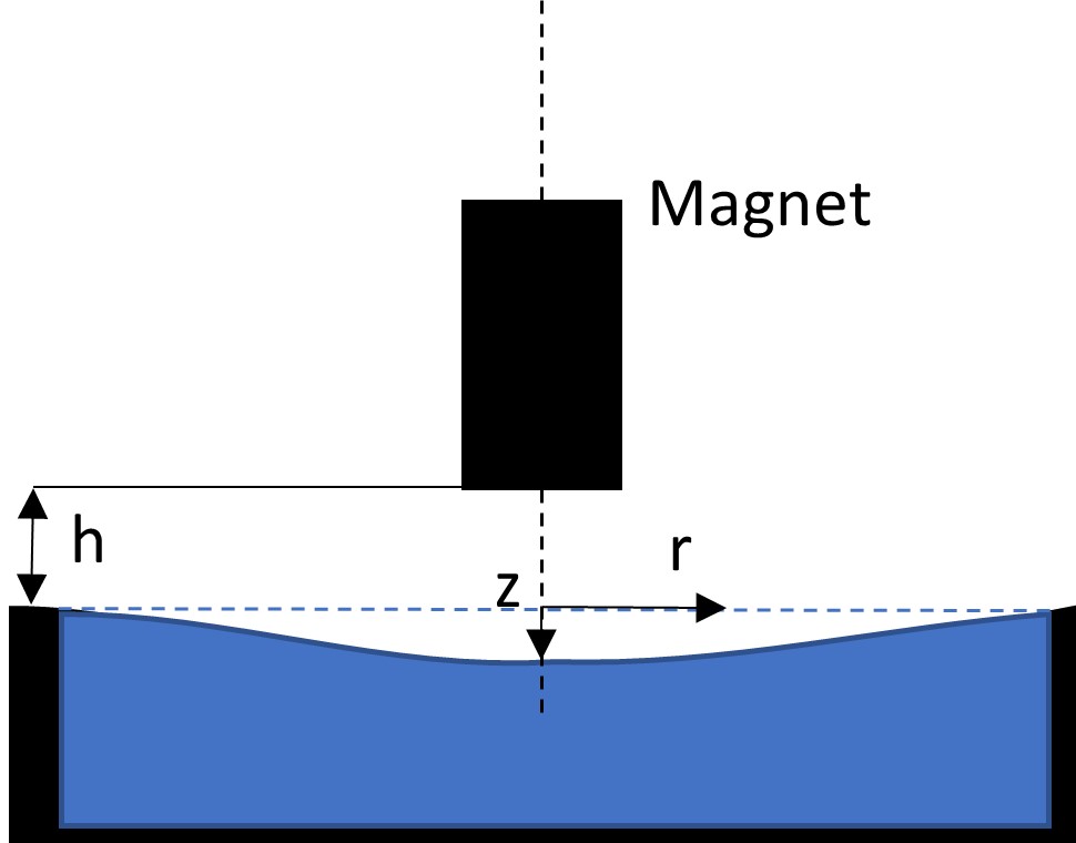
The classical theory of the Moses effect states that the shape of the "well" formed by the permanent magnet on the diamagnetic liquid surface emerges due to the application of a permanent magnetic field Bormashenko (2019); Shulman et al. (2023). For the cylindrically symmetrical magnetic field , the following expression predicts the well’s shape, displayed in Figure 2:
| (2) |
where and are the magnetic susceptibility and the density of the liquid, respectively, is the magnetic permittivity of vacuum, and is the separation between the magnet and non-deformed liquid/vapor interface.
The eq.(2) neglects the surface tension of the liquid/vapor interface. The Young-Laplace equation defining the shape of the liquid-air interface deformed by a time-independent magnetic field, which takes into account surface tension is derived in Gendelman et al. (2019):
| (3) |
with its solution:
| (4) |
Here and are the modified Bessel functions of the first and the second kind, respectively.
| (5) |
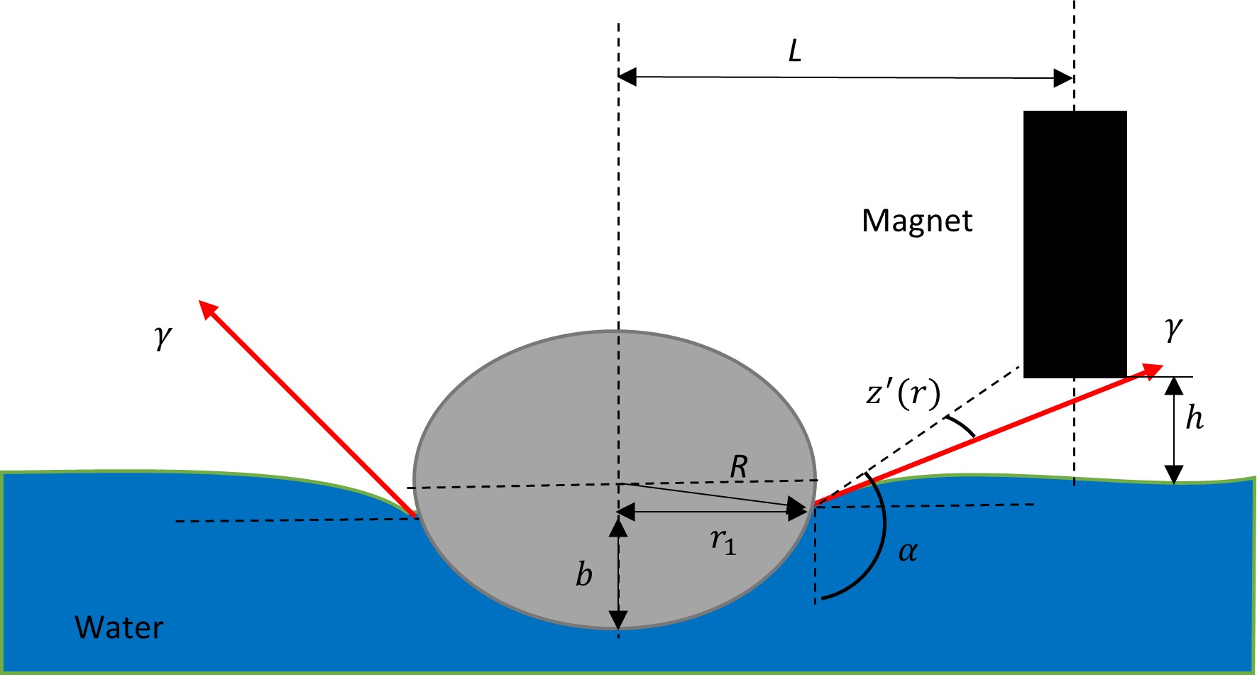
The lateral capillary force on the particle can be calculated by integrating the interfacial tension of the meniscus along the contact line Fortes (1982). The lateral projection of the interfacial tension of the meniscus is the component of the tension force that acts in the direction perpendicular to the contact line. It can be calculated using the angle between the tangent to the liquid surface and the vertical direction, and the slope of the disturbed liquid surface caused by the magnetic field. The equation for the lateral projection of the interfacial tension is , see Fig. 4. The complete integral along the contact line is :
| (6) |
where is the surface tension of the liquid, is the radius of the particle, is the azimuthal angle, is the angle between the normal to the surface and the magnetic field, and is the first derivative of the surface profile with respect to .
To calculate the hydrostatic force on the particle, one can use the following equation:
| (7) |
In this equation, represents the height difference between the top and bottom surfaces of the particle at a given position and azimuthal angle . Other parameters used are the density of the liquid , the acceleration due to gravity , and a factor of 0.5 that assumes the particle has a symmetric shape. The magnetic force on the particle can be calculated as:
| (8) |
where is the magnetic moment of the particle, is the magnetic field, is the volume of the magnetic material in the particle, is the difference in magnetic susceptibility between the particle and the surrounding liquid, is the permeability of free space, and is the gradient of the square of the magnetic field.
In order to simplify the numerical calculations, it is convenient to convert the volume integral into a surface integral. This can be achieved by applying the divergence theorem, resulting in an expression for the magnetic force that involves the surface integral of the magnetic field squared, weighted by the normal vector and the change in susceptibility. Specifically, the magnetic force can be expressed as:
| (9) |
where represents the relative magnetic susceptibility of the particle, is the permeability of free space, is the surface of the particle, is the magnetic field, and is the normal vector to the surface. The corresponding square of the magnetic field was calculated assuming that the magnetic field of a permanent magnet can be approximated as the magnetic field of an ideal solenoid Shulman (2023) . For this calculation we use the Python package for the computation of the magnetic fields of Ortner and Bandeira (2020).
To determine the equilibrium position of the floating particle, the balance of forces equation can be solved numerically using finite element methods or other numerical techniques. The equilibrium position is the point at which the net force on the particle is zero, and it can be used to measure the lateral capillary force acting on the particle. The dependence of the equilibrium position on various parameters such as the surface curvature, magnetic field strength, and particle size can provide insights into the nature of intermolecular forces and their impact on the behavior of particles in liquids.
III Experimental arrangement
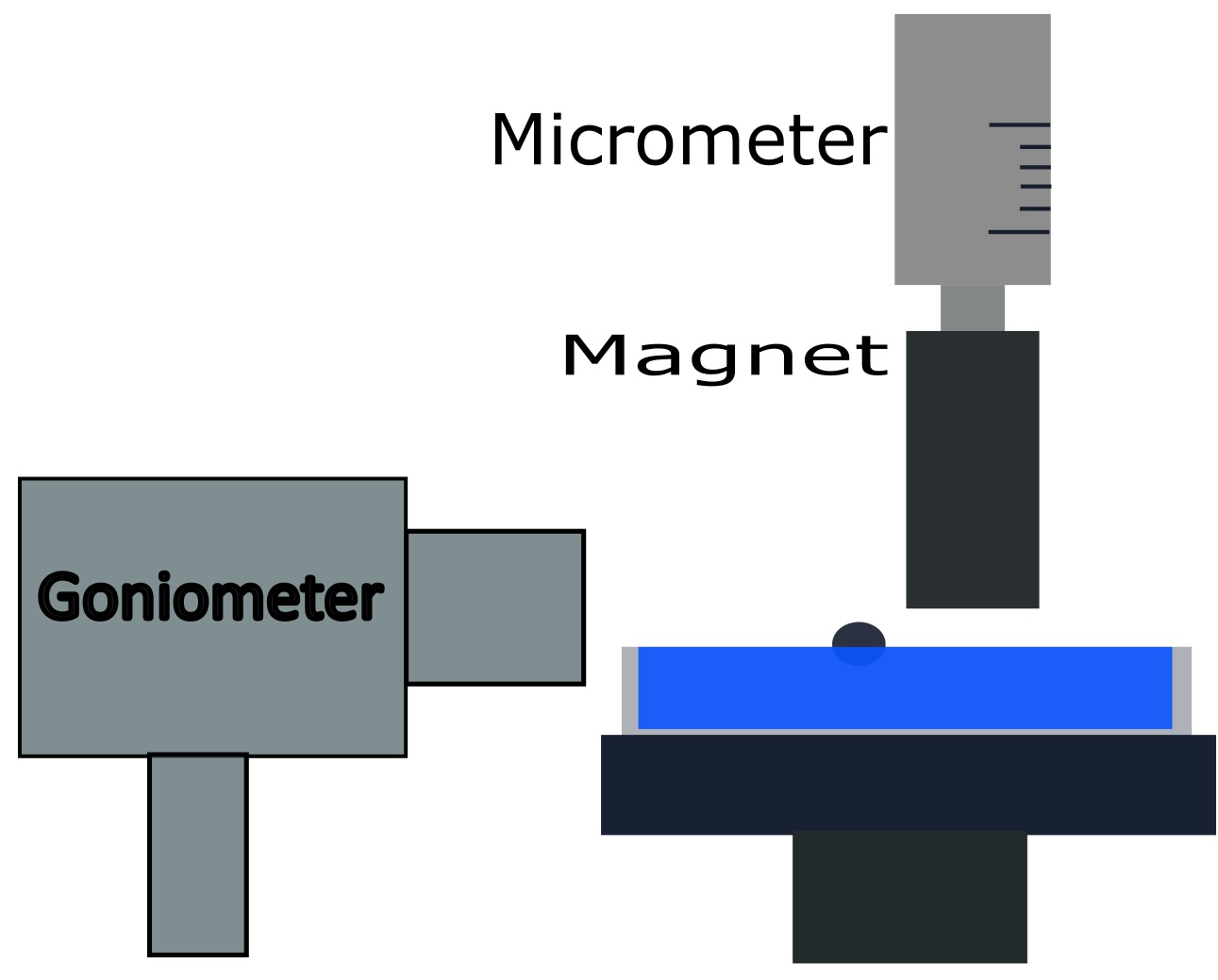
The suggested experimental technique is based on determining the coordinates of the stable equilibrium position of the particle on the water surface curved by the magnetic field. A schematic outline of the experimental setup is presented in Fig. 4. The main elements of the experimental setup, shown in Fig. 4 are:
-
1.
The sample liquid (deionized water) in the Petri dish with the diameter of 90 .
-
2.
A stack of Neodymium permanent magnets.
-
3.
A special micrometric screw fixing the precise location of the permanent magnet with a precision of 10 .
-
4.
A Rame-Hart 500 contact angle goniometer/tensiometer registering the position of the floating particle with an accuracy of 100 .
-
5.
The floating polystyrene sphere with the diameter of 2 .
The petri dish with the diameter of 90 was filled with deionized water to a depth of approximately 1 and set on top of a frame constructed from a non-ferromagnetic material. A cylindrical neodymium (NdFeB) bar magnet of with the diameter of 22.8 and the length of 30 , supplied by MAGSY, Czech, was used during the measurements. The magnetic field strength at the base center was .
The magnetic field was measured with a DC/AC GM2 Gauss Meter, manufactured by AlphaLab Inc., USA. For modeling the magnetic field of the magnet an ideal solenoid approximation has been used Shulman (2023).
The deionized water was prepared using the synergy UV water purification system from Millipore SAS (France). The specific resistivity of the water used during the experiments was . The deionized water has the following physical properties: density , volume magnetic susceptibility , surface tension .
For the experiments, polystyrene (PE) spheres with the diameter of 2 , supplied by Cospheric LLC, United States, were used. The polystyrene spheres have the following physical properties Van Krevelen and Te Nijenhuis (2009); Howe and Mark (1999): volume magnetic susceptibility , density , contact angle . The contact angle and the depth of immersion of the PE particles was measured by Rame-Hart 500 contact angle goniometer/tensiometer.
The measurements were performed as follows: the magnet was fixed at a certain position on the micrometer precision stage. The equilibrium position of the particle was measured with the goniometer. The micrometer stage lifted the magnet vertically with the step of 0.1 and the measurement was repeated.
All experiments were carried out at ambient conditions (; ).
IV Experimental Results and Discussion
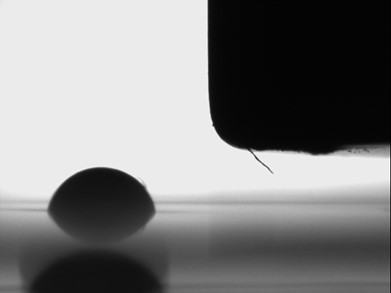
In this study, the capillary meniscus interaction between a floating particle and a surface deformation was investigated, and a setup for measuring the capillary forces using the Moses effect was developed and employed for the experimental procedures. Fig. 6 shows an image captured by the goniometer, where a meniscus formed around the floating particle is clearly visible, while the well formed by the magnetic field cannot be seen due to its small size.
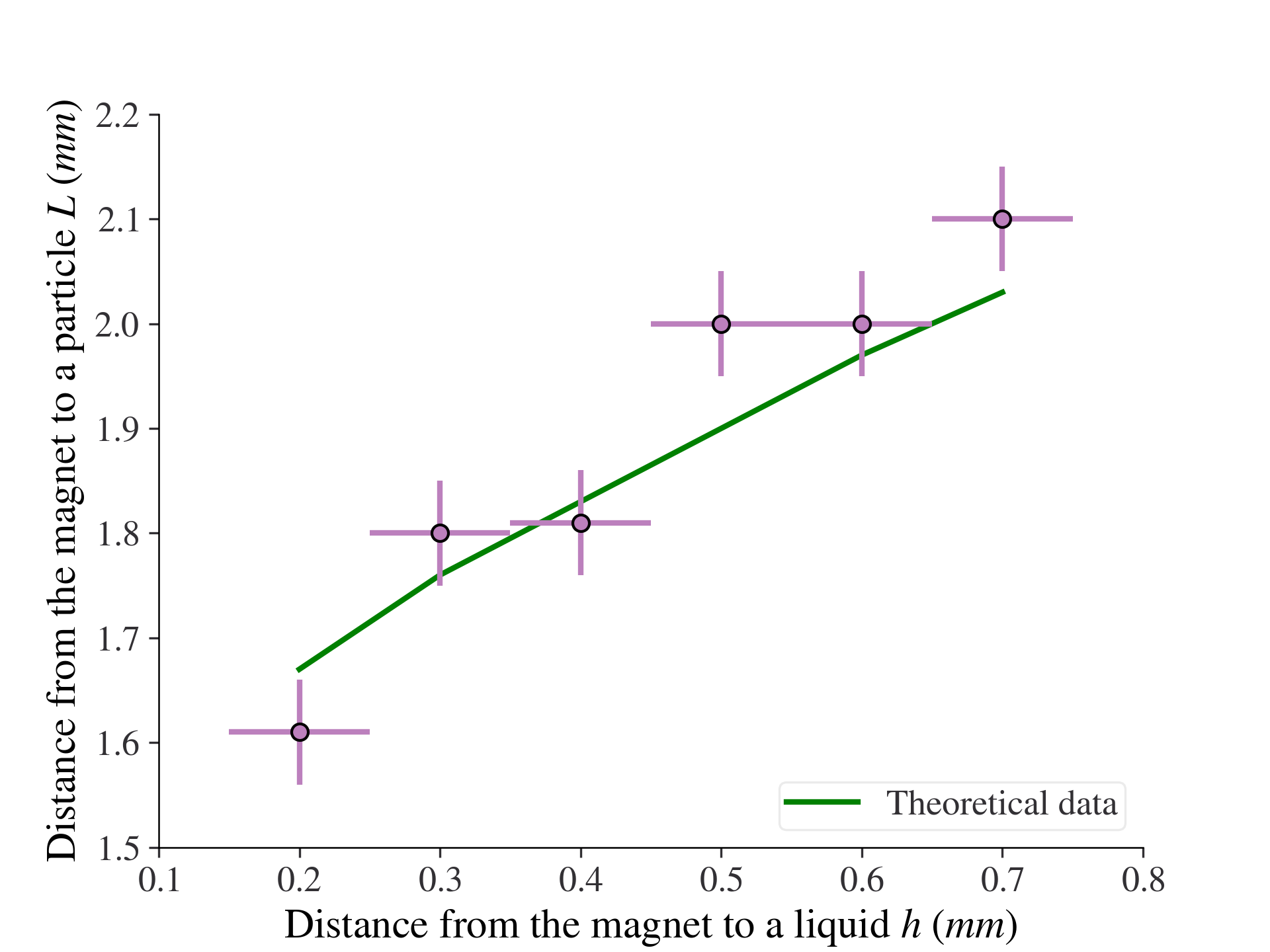
The theoretical calculations based on the numerical solution of equation (1), as described in Section 2, are illustrated with the green line in Fig. 6. The graph demonstrates that the horizontal distance between the center of the floating particle and the edge of the magnet increases with the increase of the vertical distance of the magnet from the liquid. This effect can be explained by considering the change in the forces acting on the particle due to the magnet movement. As the magnet moves vertically, the horizontal component of the magnetic field acting on the particle does not change as much as the capillary attraction forces. The capillary attraction forces, however, decrease significantly since the well and, therefore, the surface slope decrease when the vertical distance from the magnet increases. The experimental error bars are also demonstrated, and it is evident that the theoretical curve falls well within the error bars, thus confirming the theoretical model by the experimental investigations.
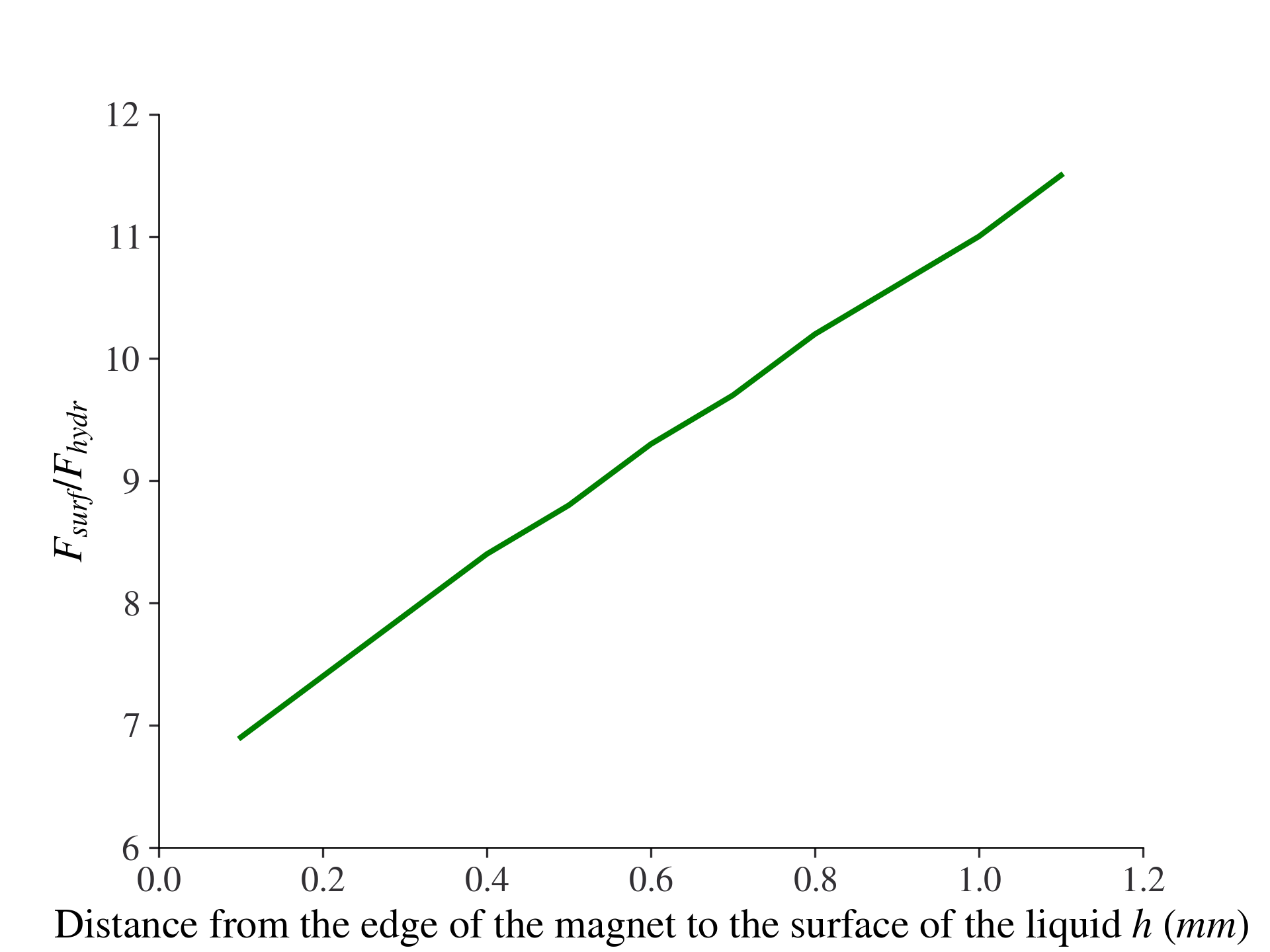
Fig. 8 shows the ratio of the surface forces to the forces of hydrostatic pressure in the equilibrium position. This ratio almost linearly increases with the increase of the distance from the magnet to the liquid. The near-linear dependence can be explained by the fact that hydrostatic pressure acts on the surface, meaning that it has a second-degree dependence on the surface area, while surface tension acts on the contact line, having a first-degree dependence on the area. Therefore, as the curvature becomes less pronounced, we get a linear dependence between the forces of hydrostatic pressure and surface forces. From this, we can also conclude that the surface forces are about 10 times bigger than the hydrostatic forces, and in most cases, only the surface forces need to be taken into account.
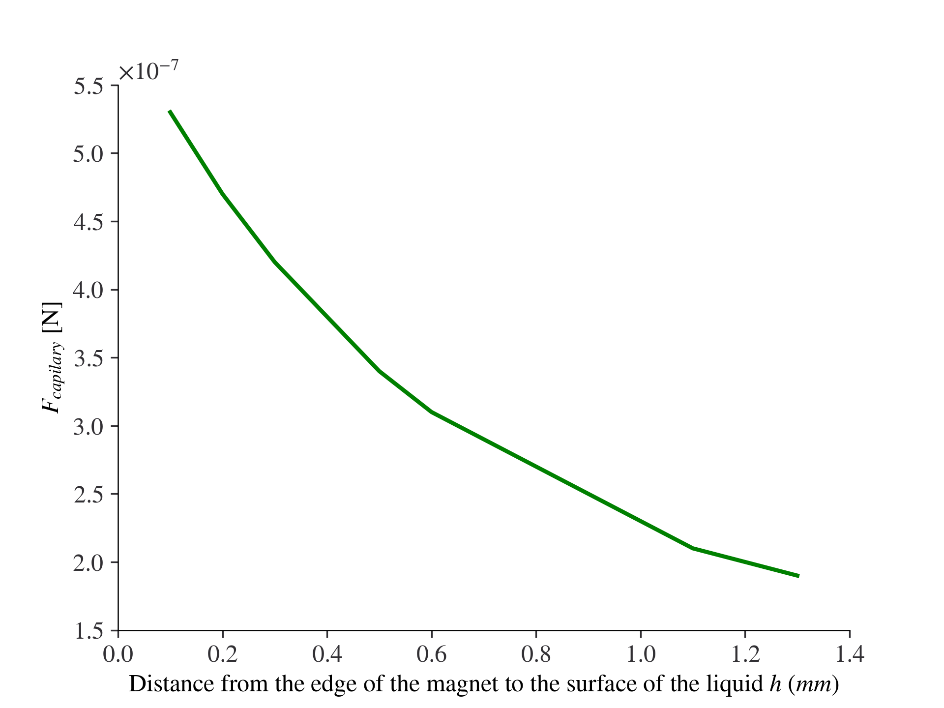
Fig. 8 shows the sum of all capillary forces (surface forces and the forces of hydrostatic pressure), which is equal to the magnetic force as described by equation (1). The graph demonstrates that the capillary forces decrease exponentially as the distance of the magnet from the liquid surface increases. This decrease in the capillary forces can be explained by the decreasing surface slope caused by the magnetic field.
Although the results of this paper apply exclusively to spherical particles partially immersed in fluid, the developed theoretical model can be applied without substantial transformation to other geometries of interest and to superhydrophobic bodies not immersed in a liquid.
V Conclusion
In this study, we have presented a method for measuring the capillary meniscus interaction between a floating particle and a surface deformation. The method is based on the Moses effect, and it was shown to produce reliable results that agree well with theoretical calculations.
The experimental results confirmed that the horizontal distance between the center of the floating particle and the edge of the magnet increases with the increase of the vertical distance of the magnet from the liquid. The near-linear dependence of the ratio of the surface forces to the forces of hydrostatic pressure on the distance from the magnet to the liquid was explained by the different dependence of these forces on the surface area.
The developed theoretical model can be applied without substantial transformation to other geometries of interest and to superhydrophobic bodies non-immersed in a liquid. We expect that the method and the theoretical model will be useful for a range of applications, including the design of micro- and nanoscale devices that rely on capillary forces.
Previous research has shown that the contact angle, which is an important parameter in measuring lateral capillary forces, can vary with time depending on factors such as vapor environment and temperature Xinping et al. (2005); Yekta-Fard and Ponter (1988); Kwok and Neumann (1999). The contact method for measuring these forces requires a high level of cleanliness for the contact element, and the element must be cleaned after each experiment. Additionally, the contact angle of the element can change during the experiment, making non-contact measurement methods advantageous. The experimental setup described in this study can be utilized for a variety of applications, such as measuring capillary angles, fluid properties, and particle surface properties.
Overall, our study highlights the importance of understanding and characterizing capillary forces, and we hope that it will inspire further research in this area.
Conflict of Interest
The author has no conflicts to disclose.
References
- Nicolson (1949) M. Nicolson, Mathematical Proceedings of the Cambridge Philosophical Society, Cambridge University Press 45, 288 (1949).
- Gifford and Scriven (1971) W. Gifford and L. Scriven, Chemical Engineering Science 26, 287 (1971).
- Princen (1969) H. Princen, Surface and colloid science 2, 1 (1969).
- Chan et al. (1981) D. Chan, J. Henry Jr, and L. White, Journal of Colloid and Interface Science 79, 410 (1981).
- Fortes (1982) M. Fortes, Canadian Journal of Chemistry 60, 2889 (1982).
- Allain and Cloitre (1993) C. Allain and M. Cloitre, Journal of colloid and interface science 157, 269 (1993).
- Danov and Kralchevsky (2010) K. D. Danov and P. A. Kralchevsky, Advances in colloid and interface science 154, 91 (2010).
- Dixit and Homsy (2012) H. N. Dixit and G. Homsy, Physics of Fluids 24, 122102 (2012).
- Kralchevsky et al. (1995) P. Kralchevsky, V. Paunov, and K. Nagayama, Journal of Fluid Mechanics 299, 105 (1995).
- Paunov et al. (1993) V. Paunov, P. Kralchevsky, N. Denkov, and K. Nagayama, Journal of colloid and interface science 157, 100 (1993).
- Vassileva et al. (2005) N. D. Vassileva, D. van den Ende, F. Mugele, and J. Mellema, Langmuir 21, 11190 (2005).
- Kralchevsky et al. (1992) P. Kralchevsky, V. Paunov, I. Ivanov, and K. Nagayama, Journal of Colloid and Interface Science 151, 79 (1992).
- Würger (2006) A. Würger, Physical Review E 74, 041402 (2006).
- Dushkin et al. (1995) C. Dushkin, P. Kralchevsky, H. Yoshimura, and K. Nagayama, Physical review letters 75, 3454 (1995).
- Velev et al. (1993) O. D. Velev, N. D. Denkov, V. N. Paunov, P. A. Kralchevsky, and K. Nagayama, Langmuir 9, 3702 (1993).
- Velev et al. (1994) O. D. Velev, N. D. Denkov, V. N. Paunov, P. A. Kralchevsky, and K. Nagayama, Journal of colloid and interface science 167, 66 (1994).
- Bormashenko (2019) E. Bormashenko, Advances in colloid and interface science 269, 1 (2019).
- Shulman et al. (2023) D. Shulman, M. Lewkowicz, and E. Bormashenko, Journal of Magnetism and Magnetic Materials , 170553 (2023).
- Gendelman et al. (2019) O. Gendelman, M. Frenkel, V. Fliagin, N. Ivanova, V. Danchuk, I. Legchenkova, A. Vilk, and E. Bormashenko, Surface Innovations 7, 194 (2019).
- Shulman (2023) D. Shulman, Journal of Magnetics 28, 1 (2023).
- Ortner and Bandeira (2020) M. Ortner and L. G. C. Bandeira, SoftwareX 11, 100466 (2020).
- Van Krevelen and Te Nijenhuis (2009) D. W. Van Krevelen and K. Te Nijenhuis, Properties of polymers: their correlation with chemical structure; their numerical estimation and prediction from additive group contributions (Elsevier, 2009).
- Howe and Mark (1999) D. Howe and J. Mark, Polymer data handbook (1999).
- Xinping et al. (2005) W. Xinping, C. Zhifang, and S. Zhiquan, Science in China Series B-Chemistry 48, 553 (2005).
- Yekta-Fard and Ponter (1988) M. Yekta-Fard and A. B. Ponter, Journal of colloid and interface science 126, 134 (1988).
- Kwok and Neumann (1999) D. Y. Kwok and A. W. Neumann, Advances in colloid and interface science 81, 167 (1999).