Optimizing Out-of-Plane Stiffness for Soft Grippers
Abstract
In this paper, we presented a data-driven framework to optimize the out-of-plane stiffness for soft grippers to achieve mechanical properties as hard-to-twist and easy-to-bend. The effectiveness of this method is demonstrated in the design of a soft pneumatic bending actuator (SPBA). First, a new objective function is defined to quantitatively evaluate the out-of-plane stiffness as well as the bending performance. Then, sensitivity analysis is conducted on the parametric model of an SPBA design to determine the optimized design parameters with the help of Finite Element Analysis (FEA). To enable the computation of numerical optimization, a data-driven approach is employed to learn a cost function that directly represents the out-of-plane stiffness as a differentiable function of the design variables. A gradient-based method is used to maximize the out-of-plane stiffness of the SPBA while ensuring specific bending performance. The effectiveness of our method has been demonstrated in physical experiments taken on 3D-printed grippers.
Index Terms:
Soft Robotics, Design Optimization, Out-of-Plane Stiffness, Stable Grasping, Data-Driven Optimization,I Introduction
The Soft gripper has caught much attention due to its good adaptability to the shape of objects to be manipulated. However, the high flexibility of materials (with low Young’s modulus) and structures (with low stiffness) used on soft grippers can also lead to undesired out-of-plane deformation, which reduces grasping stability [1]. To overcome this deficiency, some researchers added long fiber winding or auxiliary structures on soft actuators to enhance the stiffness in different aspects [2, 3, 4, 1]. The geometry of a soft gripper design was also optimized to reduce the maximal strain (therefore material failure) in [5]. Out-of-plane deformation was not considered in their approach. Moreover, including physical simulation by finite element analysis (FEA) in the loop of numerical optimization is prone to the problem of robustness. Specifically, the optimization process may fail to converge because of the numerical instability of nonlinear FEA. Differently, we present a data-driven approach in this paper that shifts the finite element (FE) computation to the step of dataset preparation. This strategy significantly improves the robustness of our method.
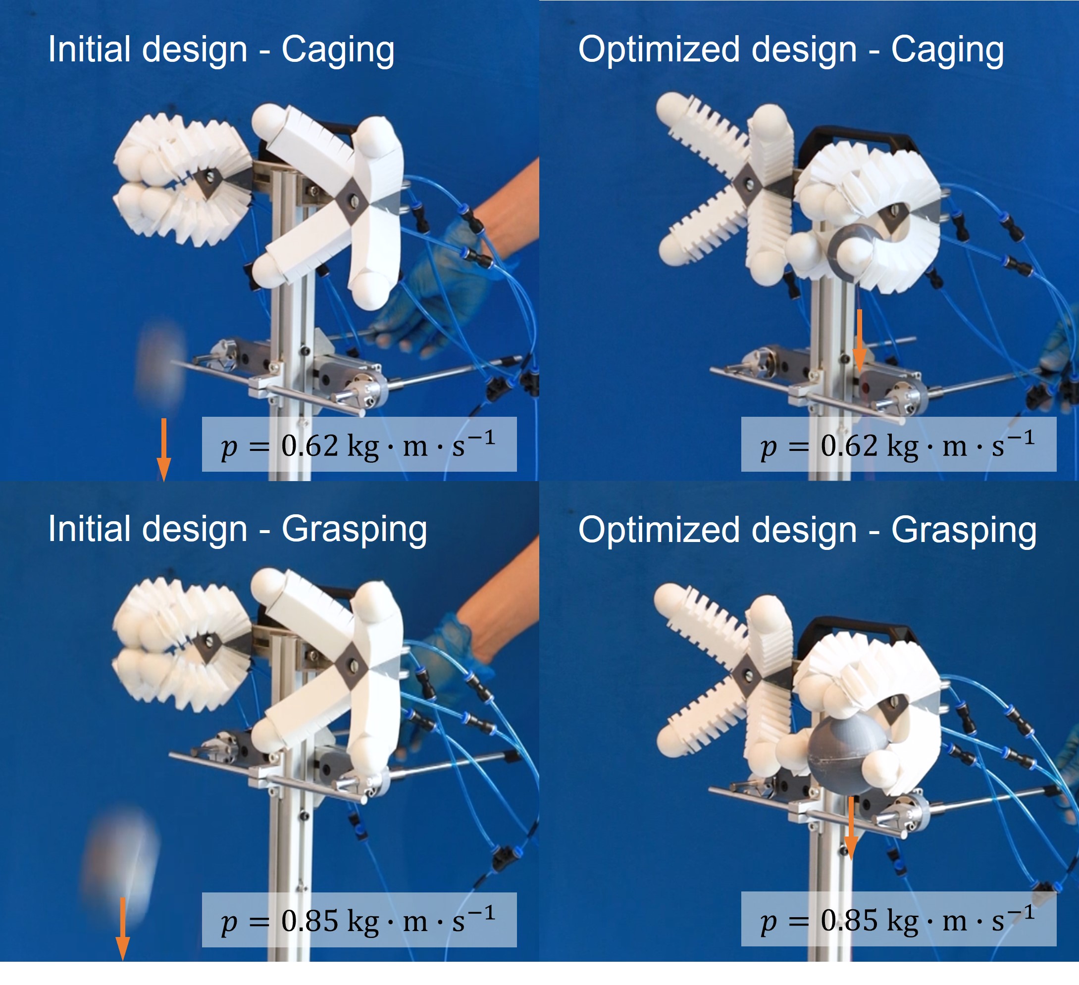
To optimize the out-of-plane stiffness for soft grippers, we define an objective function that can quantitatively capture the requirement to enhance the out-of-plane stiffness via the bending results of a soft actuator when contacting an asymmetric obstacle. With the help of FEA, we conduct sensitivity analysis to effectively reduce the dimension of variables on the parametric model of a soft pneumatic bending actuator (SPBA). A data-driven optimization framework is proposed in this paper to fit the selected design variables and their corresponding performance defined by the objective function to a differentiable hypersurface in a high-dimensional space. The hypersurface can predict the performance of different geometry in the design space, and therefore can also be employed to find an optimal design by the gradient-based optimization solver. We can effectively maximize the out-of-plane stiffness on the SPBA design while keeping a required bending behavior and applying the same air pressure as pneumatic actuation. Physical experiments have been tested to verify the effectiveness of our method under different loads (see Fig.1 for an example).
Our work makes the following technical contributions.
-
•
An objective function to quantitatively evaluate the out-of-plane stiffness under a fixed bending requirement;
-
•
A data-driven framework for optimizing the out-of-plane stiffness on parameterized gripper models by learning a differentiable function;
-
•
A novel design of physical experiment that can apply repeatable loads on grasped/caged objects to study grasping stability on soft grippers.
The SPBA design is employed to demonstrate the functionality of our method. However, the methodology presented here can be generally applied to different designs of soft grippers.
II Related Work
II-A Out-of-plane deformation
Although grippers using soft-bending actuators have received a lot of attention and been widely studied since the work in [6], few people have conducted in-depth research on the failure of soft grippers. Scharff et al. [1] were the first to realize that the deformation outward from the bending plane under asymmetric load is a critical issue for unexpected buckling and twisting, which is similar to the two patterns of grasping failure of spherical objects as reported in [7]. By increasing the torsional constant and adding a stiffening structure, Scharff et al. [1] reduced the out-of-plane deformation and improved the grip performance.
Soft-rigid hybrid actuators could be an alternative strategy to solve the problem of out-of-plane deformation. In nature, the exoskeletons of crustaceans such as lobster also have similar structures, and hybrid actuators inspired by it have been designed and studied in [8, 9, 10], although the authors may not be aware of the effect of this hinge-based structure on the out-of-plane stiffness. In contrast, Lotfiani et al. [11] embedded hinges-based skeleton during the casting of soft actuators to improve their torsional stiffness. Morrow et al. [12] used 3D printed nails (fingertips) to avoid out-of-plane buckling.
Torsion coupled with bending is not always detrimental. Some researchers have achieved controllable twists through material or structural design and obtained winding grippers like vines and tentacles (ref. [13, 14]). The joint locking mechanism formed by the conductive PLA bottom layer was added by Al-Rubaiai et al. [15] to limit twisting for soft fingers indirectly. Different from these existing approaches, we propose a method to reduce the out-of-plane deformation on soft grippers by optimizing the parameters of designs.
II-B Designing the mechanical properties of soft robots
The mechanical properties of soft robots mainly depend on their geometry and materials, so the desired characteristics are always designed from these two aspects. A comprehensive review can be found in [16]. Here we mainly focus on soft pneumatic robots.
Morin et al. [17] found that the distribution of materials resulted in a high degree of freedom of programmability of the expansion or collapse pattern in their research of elastic cubes made of two soft materials with different stiffness (i.e., Ecoflex and PDMS). Using the same combination of materials, Forte et al. [18] recently proposed a machine learning-based framework for the inverse design of the soft membrane that can achieve the pre-programmed deformation under inflation. Dammer et al. [5] demonstrated a 3D-printable linear actuator and optimized the geometry parameters to extend its lifetime by considering the maximal strain. In this paper, we propose to optimize the out-of-plane stiffness by changing the soft gripper’s geometry.
The bending actuators are often designed based on the mutual squeeze of two adjacent air chambers after inflation. In the research of Mosadegh et al. [19], the significant differences between the slow pneu-net (sPN) and fast pneu-net (fPN) proposed were reflected not only in the response speed but also in the actuation pressure. This pioneering work has inspired a lot of new designs for the soft pneumatic bending actuator (SPBA). For example, Altelbani et al. [20] combined 3D-printable fPN with different bending properties in various ways for powerful structural programmability. Based on sPN, Ke et al. [21] achieved pre-programmed conformal grasping by varying the thickness of the stretchable top layer corresponding to the curvature of different regions of the grasped object. We employ an fPN-based design to demonstrate the effectiveness of our approach.
II-C Metamodeling for design optimization
The data-driven approach developed in this paper adopts a strategy similar to the metamodeling research in the area of engineering design. As the abstraction of a simulation model, metamodels can effectively reduce computational or experimental costs by analytically expressing the behavior of the tested model [22]. In addition to being surrogates for simulation models, differentiable analytical expressions also enable metamodel to be widely used in design optimization. Over the past few decades, several techniques [23, 24, 25, 26] have been proposed for metamodeling, which interpolates or fits a function through some result data and predicts the new results without additional simulation computing. Theoretically, a fairly accurate metamodel can be obtained as long as the training dataset is sufficient. A review by Wang and Shan [27] summarizes five advantages of metamodel-based design optimization (MBDO), including 1) easy to interact with commercial simulators, 2) suitable for parallel computing, 3) better noise resistance, 4) excellent in visualizing the entire design space, 5) robust to error in simulation. Our data-driven framework also shares all these advantages.
Park and Dang [28] proposed a design optimization framework that integrates commercial CAD and CAE packages to enable a highly automated and fast product development process, which reduced calculation costs. Three cases of design problems with the dimensional ranging from low to high demonstrate the advantages of the framework in terms of feasibility, convenience and computational efficiency, etc. A similar approach was used in studying the collision performance of thin-walled conical tubes by Acar et al. [29]; however, the too sparse training points made the metamodel unable to obtain the optimal solution. Using a similar strategy, we develop a data-driven framework to optimize the design of soft robots, which minimizes the out-of-plane deformation by finding the ‘best’ geometric parameters of the SPBA.
III Problem Formulation
III-A Definition of out-of-plane stiffness
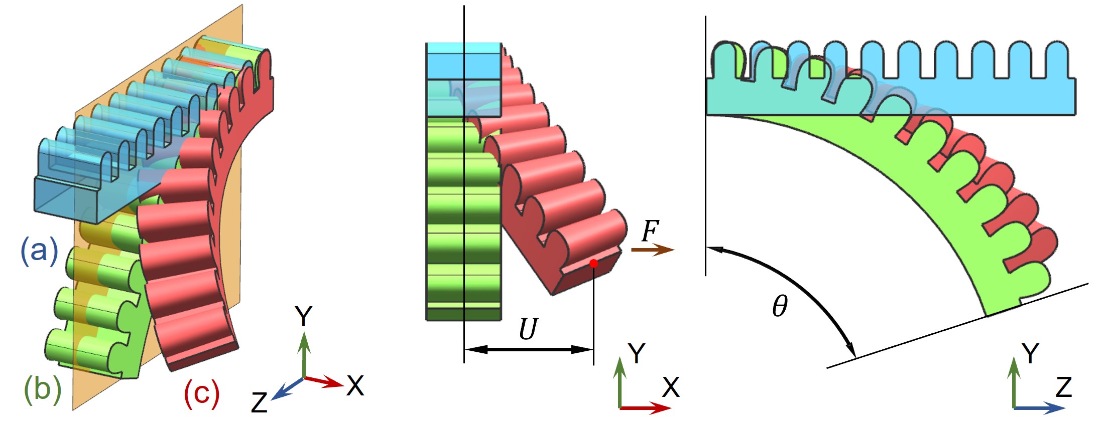
The problem to be solved here is to optimize the out-of-plane stiffness of soft grippers to become hard to sustain under the out-of-plane deformation while still keeping relatively high flexibility for pure in-plane bending. To quantitatively address the problem of out-of-plane deformation, we define the stiffness for the out-of-plane deformation by presenting an obstacle in a simple shape that passively generates asymmetric loads to a soft gripper. An actuated SPBA is used as an example to illustrate the definition (see also Fig.2).
When the SPBA (see Fig.2(a)) is actuated and starts to collide with an asymmetric obstacle, a hybrid deformation (see Fig.2(c)) composed of in-plane and lateral bending as well as torsion will be generated instead of the pure in-plane deformation (Fig.2(b)). The out-of-plane displacement is defined as the distance from the center of the SPBA’s tip to the pure bending plane. The component of the force perpendicular to the bending plane generated by the obstacle on the SPBA is named the out-of-plane deformation force, denoted by in the rest of this paper.
The out-of-plane stiffness is defined by using and as
| (1) |
where is an auxiliary parameter that prevents abnormal values caused by extremely small denominators. is used in all our tests. Inspired by the previous study [1], a ramp is employed in our work as the asymmetric obstacle. The design of the ramp should allow generating a collision force that has the components out of the bending plane (i.e., ). The unobstructed bending angle of the SPBA under the same pneumatic actuation is used to represent its bending performance. Note that the exact pneumatic actuation and the position of the ramp will be adjusted according to the dimensions of the SPBA and the required unobstructed bending angle .
III-B Parametric model for optimization
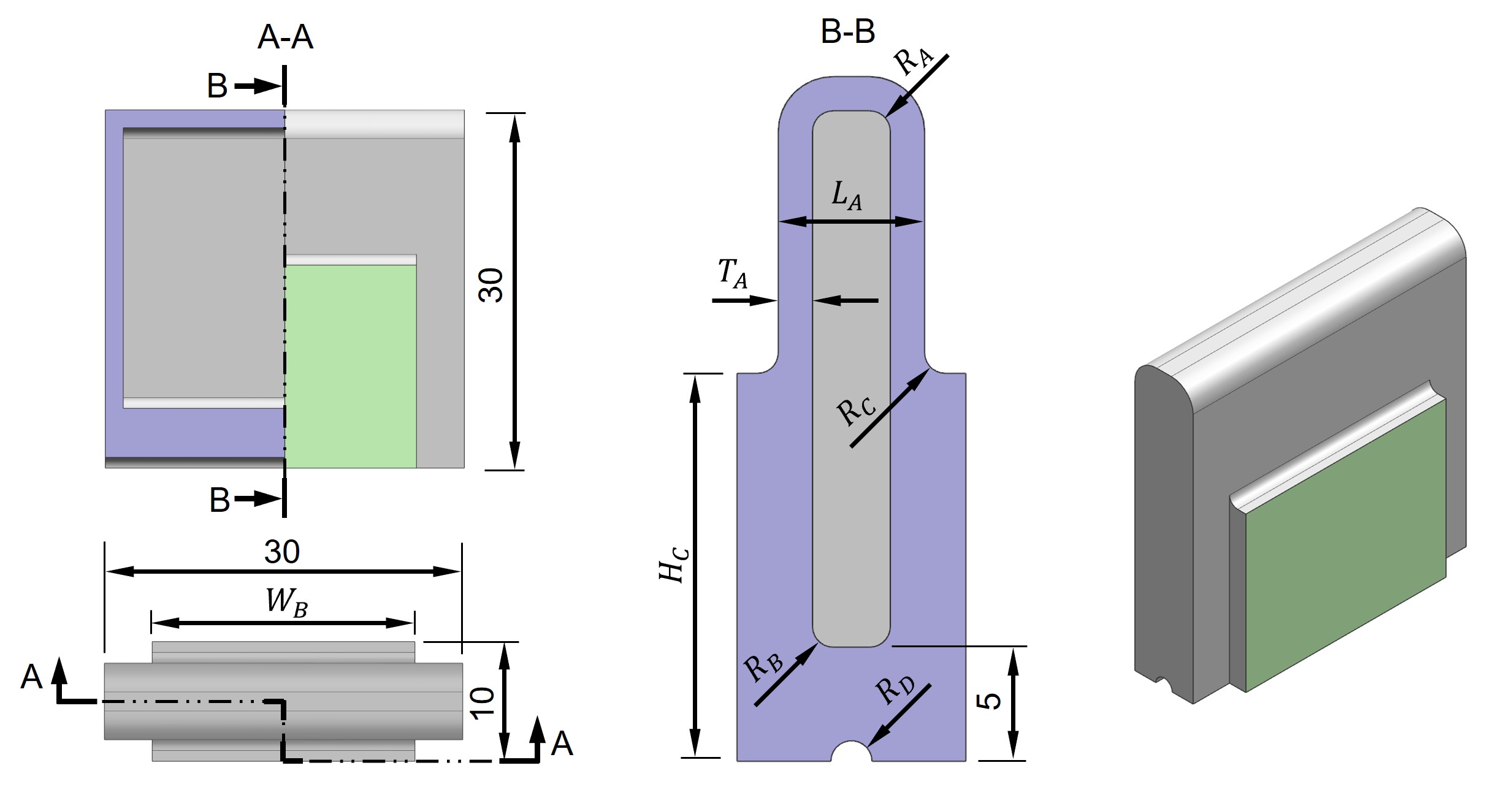
| Parameter | Symbol | Range (Unit: mm) |
| Height of the connecting section | ||
| Outer length of the air-chamber | ||
| Fillet radius of the ceiling | ||
| Fillet radius of the floor | ||
| Fillet radius on the connecting section | ||
| Radius of the bottom groove | ||
| Thickness of the chamber wall | ||
| Width of the connecting section |
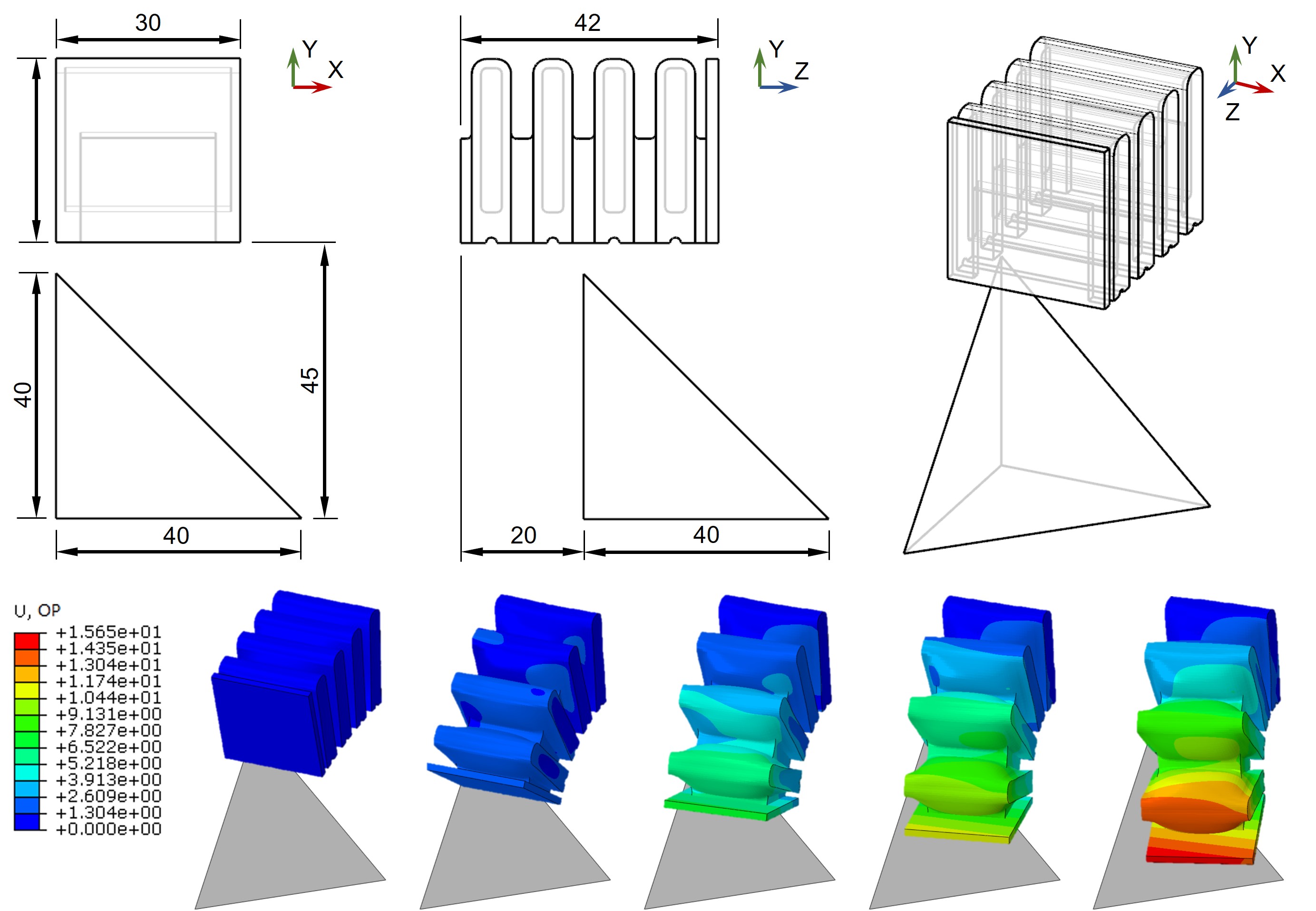
In this paper, an SPBA based on fPN is employed to demonstrate how the optimization is conducted on a parametric design. The SPBA consists of multiple repeated units having the same design, where each unit has its width, height and length as . Unlike the traditional fPN design that is widely used, the width dimension of the connecting block (highlighted in green color in Fig.3) is allowed to be different from the unit’s width. As a result, a gap can be formed between two neighboring units, and the influence of the gap on stiffness can be controlled by the design parameters and . The thickness of the bottom layer is fixed as in our design. To enlarge the bending flexibility, semicircular grooves with variable radius are added below each air chamber. Also, to understand the influence of fillet size on the SPBA, round corners with variable radii are added to the inner air chambers and the top of the connecting sections (i.e., , , and ). Eight design parameters contained in the initial design are shown in Fig. 3, and the ranges of these parameters are given in the table.
IV Data-Driven Optimization
We proposed a data-driven approach to optimize the out-of-plane stiffness, in which FE simulations of soft grippers under different asymmetric loads are conducted to generate the dataset for learning. To avoid a learning process that is too time-consuming, we need to control the complexity of the model involved in FE simulation. Therefore, an SPBA with four aforementioned units (as a parametric model) reduces the computational load while ensuring sufficient generality of the SPBA with more units. The dimensions of the SPBA and the ramp’s location are illustrated in Fig.4. Our FE simulations are taken on Abaqus/CAE using hexahedral meshes and a frictionless contact model. NinjaFlex is used as the material of the SPBA in this study and the Yeoh hyperelastic model in [30] is adopted for simulation.
IV-A Sensitivity analysis and model reduction
Directly meshing the parametric model introduced in Section III-B and sampling the design space of all eight parameters is impractical due to a large number of elements in the resultant mesh and the large number of samples needed for learning. Sensitivity analysis and model reduction are conducted before generating datasets for learning.
A problem first noticed was the complex meshes caused by the geometry of the air channel, which also made it very challenging to generate a full hexahedral mesh for the SPBA. If the air channel is ignored, the model can be simulated by fewer hexahedral elements, thus reducing the computing load of the simulation. Our test results show no significant difference between the simulation results with vs. without the air channel. In the free bending simulation, the maximum displacement error is only on the SPBA with four units. After presenting the obstacle, the error of bending simulation is only . Analytically, removing the air channel from the simulation can slightly increase the bending and torsion resistance of the connecting section – i.e., the level of deformation is reduced. However, we argue that the observed error is within an acceptable range, and this reduction can significantly improve the learning efficiency.
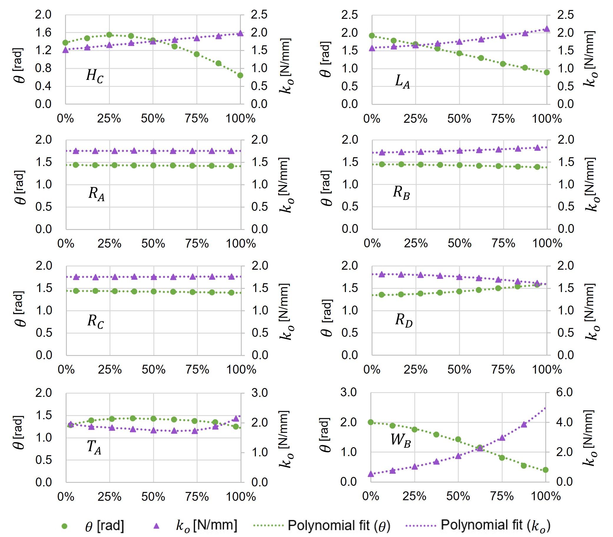
To further improve the efficiency of our data-driven optimization framework, sensitivity analysis is conducted on the eight parameters of the model to reduce the search space to a lower dimension. Only those parameters that can sensitively contribute to the mechanical property of easy-to-bend and hard-to-twist are kept in the learning and optimization routine. Given a fixed air pressure for pneumatic actuation, the easy-to-bend property is studied by the angle of free bending without presenting the obstacle. The sensitivity of out-of-plane stiffness (i.e., hard-to-twist) is evaluated by introducing the asymmetric obstacle under the same actuation. The whole range of each design parameter is uniformly sampled at 9 points to evaluate how the values of and are influenced by this design parameter. The other seven parameters are kept as the median of their corresponding ranges when changing one parameter. The results are shown in Fig.5.
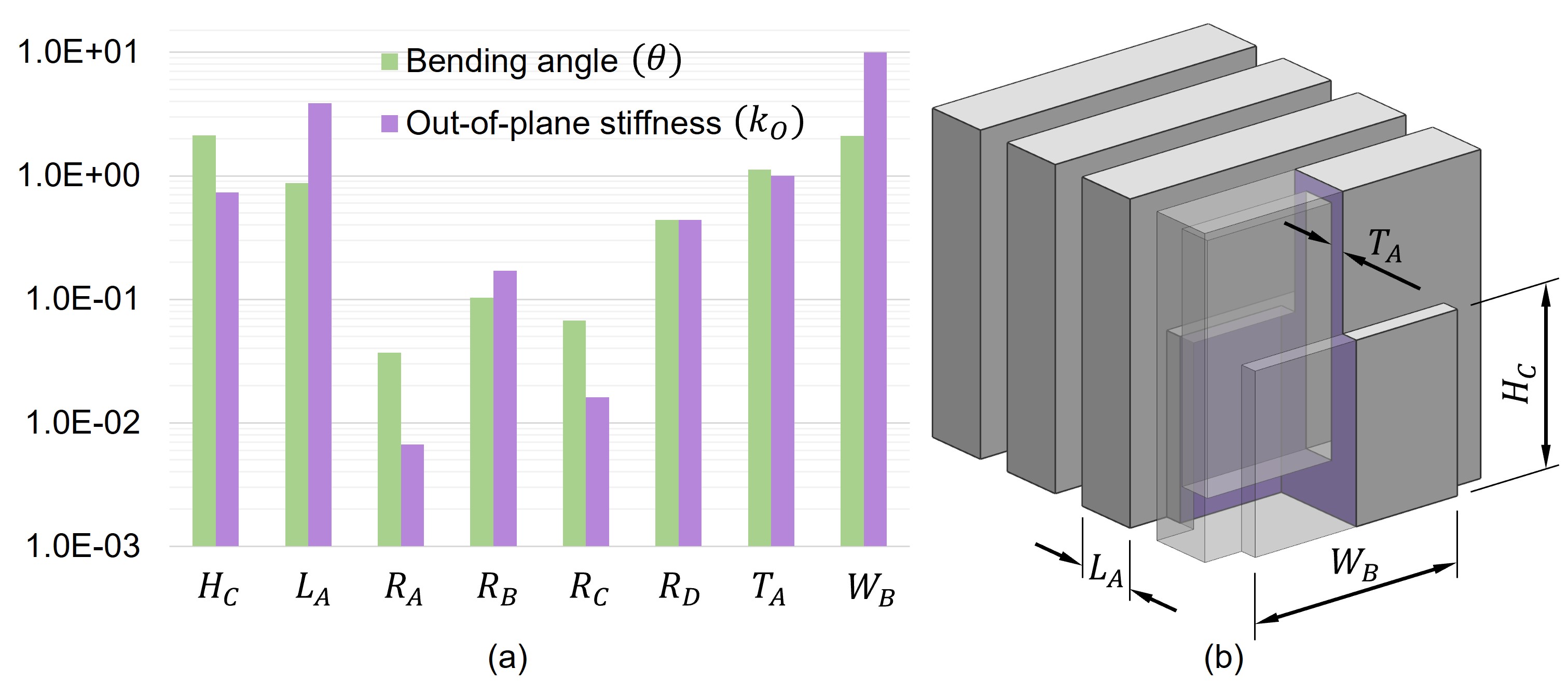
Polynomial curves are employed to fit the sample points given in Fig.5, and the maximal magnitude of gradient on the curve for each design parameter is considered as the sensitivity of each parameter and plotted as a bar chart in Fig.6(a). It can be observed that the fillet parameters have almost no influence on the performance of the designed model. Although the response of cannot be ignored, we still only retain the four parameters with the highest response (i.e., and ) in the following learning and optimization process. This is because the amount of training samples required to learn a 5-dimension design space is much larger than 4-dimensional. After this simplification, the parametric model with only four parameters is shown in Fig.6(b). After removing some parameters, the ranges of retained parameters were slightly changed into the ranges below.
| (2) | ||||
Note that the values of and were constrained according to the model’s feasibility.
IV-B Data-driven modeling
Gradient-based optimization is employed in our work to determine a design with the ‘best’ parameters that can provide strong out-of-plane stiffness while keeping good flexibility in bending. Directly computing the derivative of with by numerical difference is prone to the problem of truncation error and the case of not converging in nonlinear FE computing when hyperelastic materials are employed. Differently, we conduct a data-driven approach to learn a set of proxy functions , and for the out-of-plane displacement , the out-of-plane deformation force and the unobstructed bending angle respectively. All are represented as continuous functions w.r.t. .
Relatively uniform samples need to be generated in the 4D space of design parameters. The Sobol sequence has become a favorable tool for quasi-random sampling because of its high dispersion under a small number of samples and good uniformity under high-dimensional problems [31]. We first use the Sobol sequence to generate random points in inside a hyper-cube with unit length. Then, each random point is converted to a sample () in the design space of and according to their feasible ranges (i.e., Eq.(2)). The points that do not satisfy the constraint will be excluded. For each sample in the feasible region, two FE simulations with and without presenting the obstacles are conducted with a fixed air pressure to obtain its corresponding values of , and . When the nonlinear FE simulation at a sample point does not converge, we randomly generate another sample around this point and conduct the FE simulation again until it converges.
After collecting enough points and their corresponding values of , a regression model based on the neural network of radial basis functions (RBF) [25, 32, 33] is computed as
| (3) |
Three different functions are learned for , and . For ease of explanation, we take as an example to introduce the fitting method of the RBF network. The RBF for can be expressed as a weighted summation equation as
| (4) |
is the basis function, where the 2D thin-plate spline function form [33] is used in our implementation. That is
| (5) |
is the weight for each basis function. In this formulation, means the centre of each basis function, means the distance between the input argument and each centre, which can also be denoted as . Collocation strategy is employed here – i.e., each sample is employed for the center of a basis function as . is a polynomial term related to the basis function used for affine transformation, which is
| (6) |
The function can be determined by imposing the interpolation constraints in Eq.(3) and the compatibility conditions to compute the values of s and s as unknown variables. and can be obtained in the same way.
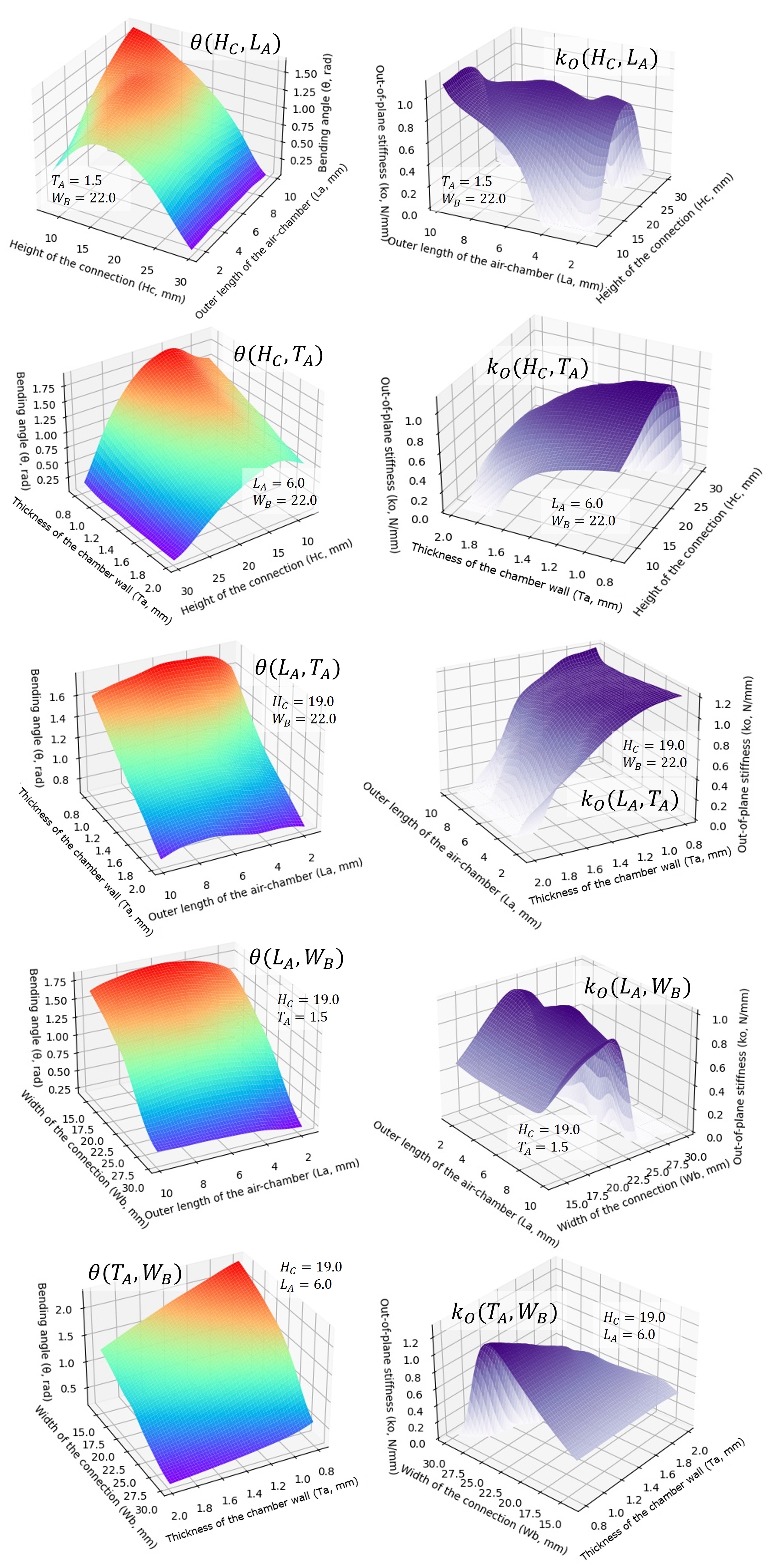
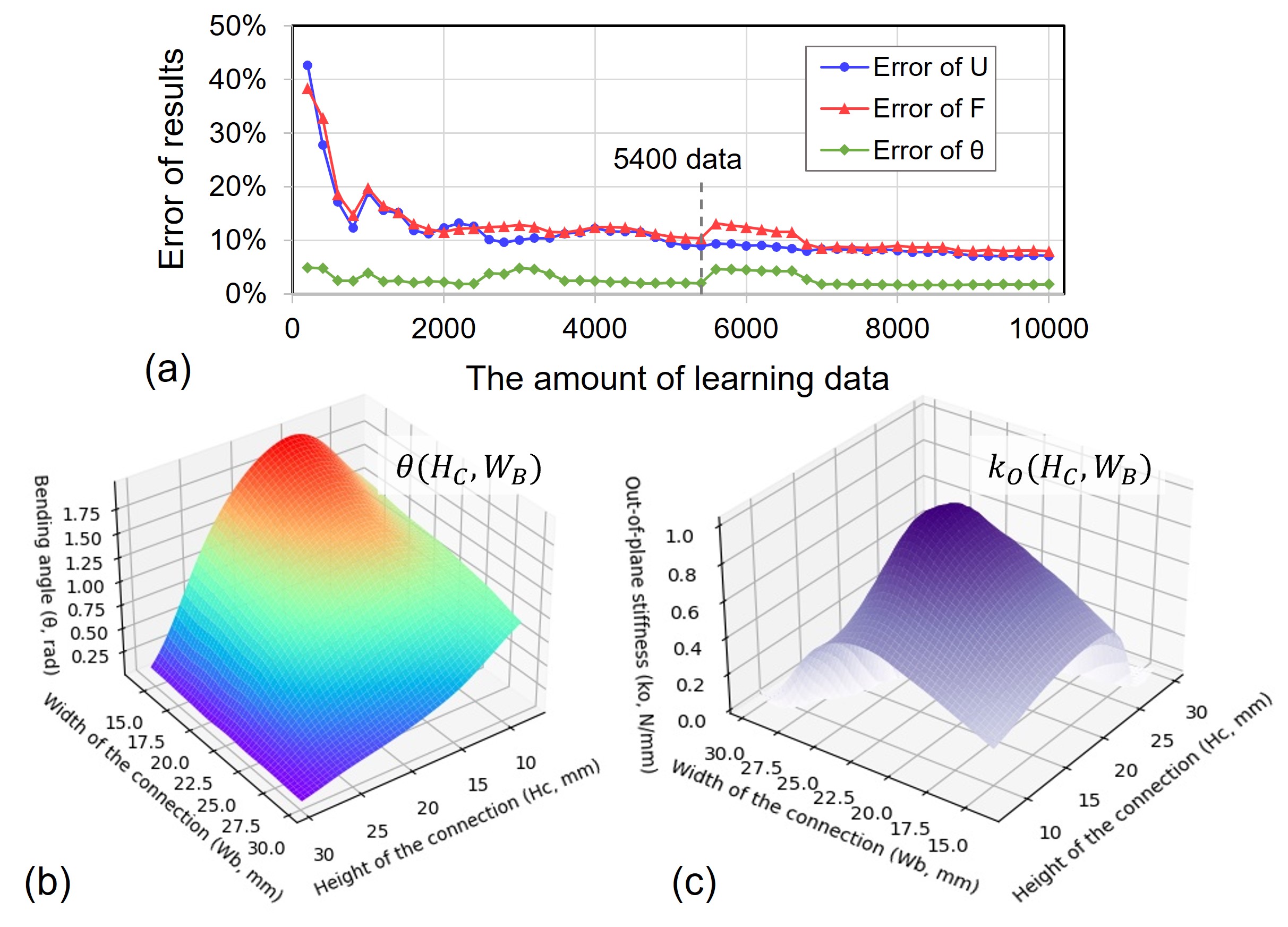
To evaluate the accuracy of fitting results, we define the fitting error as (named as coefficient of variation). is the standard deviation of the differences between the estimated values and the real values, and is the mean of real values. 80% of the dataset is used for training and the remaining 20% is employed for testing. We conducted a study by using different numbers of samples in the training. The results are shown in Fig.7(a). It was found that the set of 5400 learning samples (i.e., samples for fitting) achieves a good balance between accuracy and efficiency. We use the model trained by samples in the rest of this paper. The unobstructed bending function and the out-of-plane stiffness function obtained from learning are visualized in Fig.7(b) and (c).
IV-C Numerical optimization
After obtaining the differentiable proxy functions , and , we are able to solve the problem as follows to optimize the out-of-plane stiffness of the SPBA while keeping its flexibility in unobstructed bending.
| (7) |
where is the feasible region of the SPBA design as constraints defined in Eq.(2). The constraint gives the required angle in unobstructed bending as , which is a value proportional to the number of units used in the SPBA. For example, to achieve a bending angle of about with 7 units under the pressure of 100kPa, the constraint here should be .
V Results and Experimental Verification
We first tested the optimization results on a finger with 4 repeated SPBA units, which is consistent with the optimization setup. After that, the experimental tests are conducted on a gripper with four fingers to verify the performance of design optimized by our method.
V-A Results on 4-unit SPBA
The sequential least-squares programming is used in our work to solve the optimization problem defined in Eq.(7). The parameters of the initial guess (by using the median of the design parameter’s range) and the optimized design are listed and compared in Table I, and the performances of the two designs are compared in both FE simulation and physical tests.
| Symbol | Initial design | Optimized design | |
| Parameter | (mm) | 19.0 | 8.814 |
| (mm) | 6.0 | 9.999 | |
| (mm) | 1.5 | 1.0 | |
| (mm) | 22.0 | 30.0 | |
| FEA Result | (N / mm) | 0.807 | 1.518 |
| (rad) | 1.514 | 1.500 | |
| Physical Result | (N / mm) | 0.965 | 1.689 |
| (rad) | 1.492 | 1.477 |
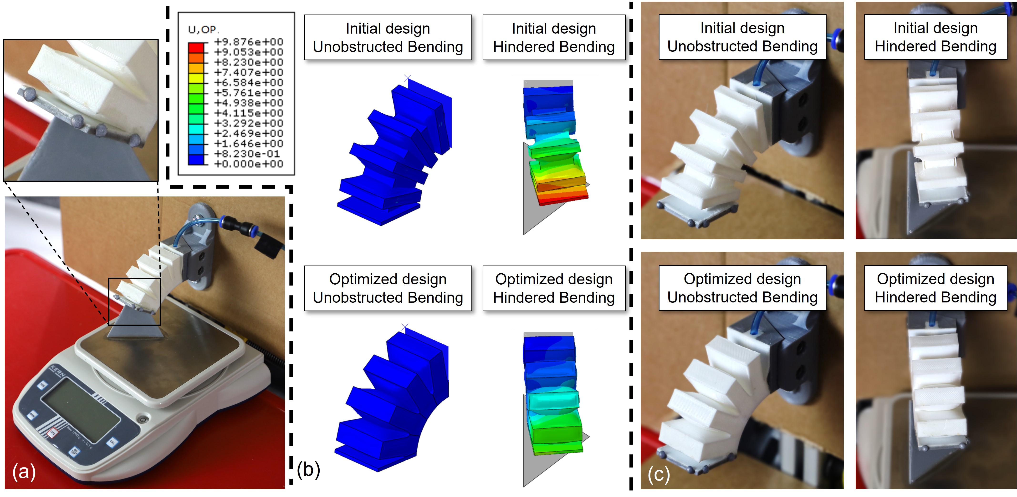
The material properties and simulation models employed in FEA-based verification are the same as those used in learning and optimization. It can be observed from Fig.8(b) and Table I that the out-of-plane stiffness increases by about when using the same actuation pressure as and precisely keeping the unobstructed bending angle as 1.5rad.
The physical tests are conducted on 4-unit SPBAs 3D printed by filament deposition using NinjaFlex 85A. The experiment setup is as given in Fig.8(a, c), where a ramp is fixed on an electronic scale (KERN EHA1000-1) to measure the out-of-plane deformation force. The out-of-plane displacement and the bending angle are obtained by using a vision system. As a result, about a increase can be observed on the out-of-plane stiffness (see Table I) while keeping nearly the same unobstructed bending angle . This result is consistent with the FEA-based verification.
V-B Hardware for grasping experiment
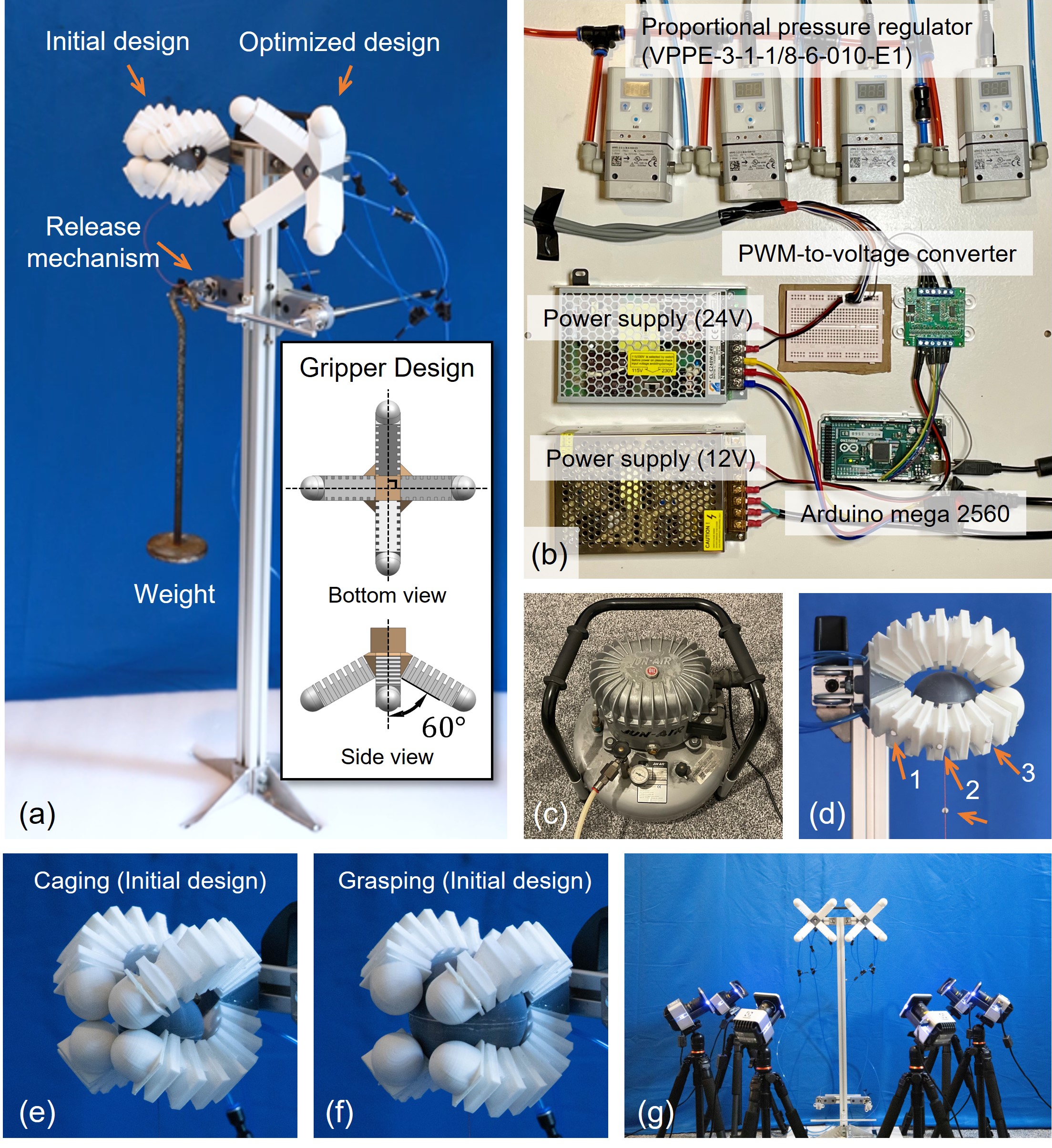
Based on the optimized design of the SPBA unit obtained above, we designed a gripper to test and verify the generalized performance of our optimization. The gripper consists of 4 fingers, where each finger is formed by 7 repeated SPBA units and a hemispherical fingertip. As shown in Fig.9(a), the assembly direction of the fingers is 60° from the central axis.
Physical experiments are taken on two grippers (initial design vs. optimized design) with 7-unit SPBAs that are 3D printed by NinjaFlex, where the hemispheres at the tips of 4 fingers are made by PLA. As shown in Fig.9(a), both grippers are mounted on a frame that is able to apply quasi-static loads and dynamic loads (by the designed release mechanism) onto the caged/grasped objects. The air compressor and the pressure control module employed in our hardware setup are shown in Fig.9(b, c). To measure the out-of-plane displacements of the fingers, a motion capture system with six Vicon Vero v1.3 cameras (Res.: pixels) is used to track the 3D positions of markers. The system can provide real-time data streaming up to 250FPS. For each finger, three markers are placed on the top of the 2nd, 4th, and the 6th bellows (see Fig.9(d)). The bending plane can be determined by the position of these markers under a collision-free bending. The performance of the optimized soft gripper in both caging (Fig.9(e)) and grasping (Fig.9(f)) are tested in our experiments. Note that air pressure is fixed as 100kPa for soft grippers in all experiments reported in this paper.
V-C Quasi-static experiment
The experiment aims to compare the out-of-plane stiffness of the gripper fingers on the designs before and after optimization. In order to facilitate the measurement and avoid the influence of inertia on the results, a quasi-static load is applied on a caged sphere (Diameter: 50mm) to pull it out of the gripper slowly through an inextensible string.
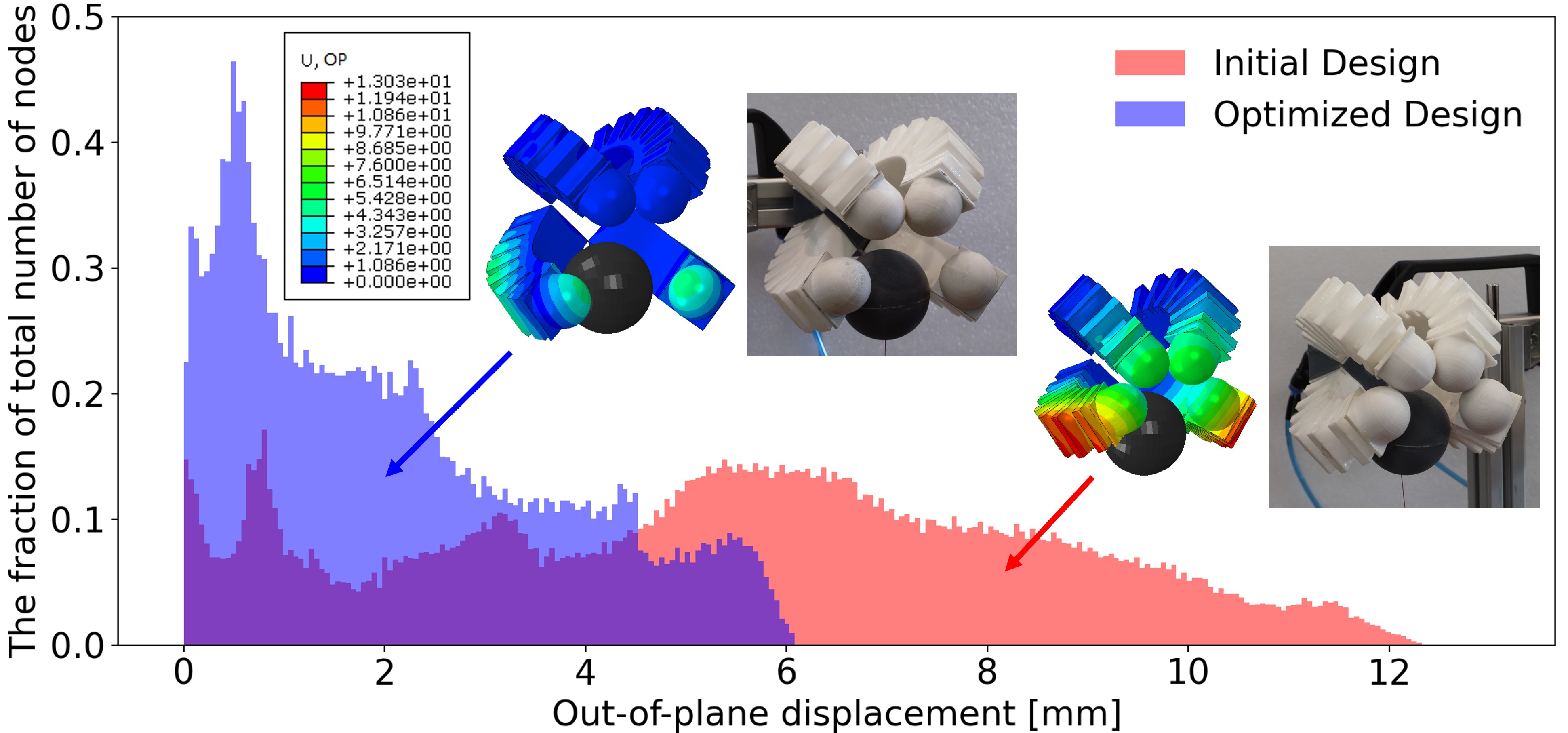
In the FE simulation, a displacement of 40mm is applied to the sphere before it escaped from the cage. The results can be found in Fig.10. The out-of-plane displacements on all nodes of FEA results are visualized as the colormap and the statistical histograms. It can be observed that the optimized gripper has smaller out-of-plane displacements. This result also demonstrates that the optimization taken on a simplified model with 4 SPBA units can still show its superiority of the out-of-plane stiffness on the gripper with 7 repeated units.
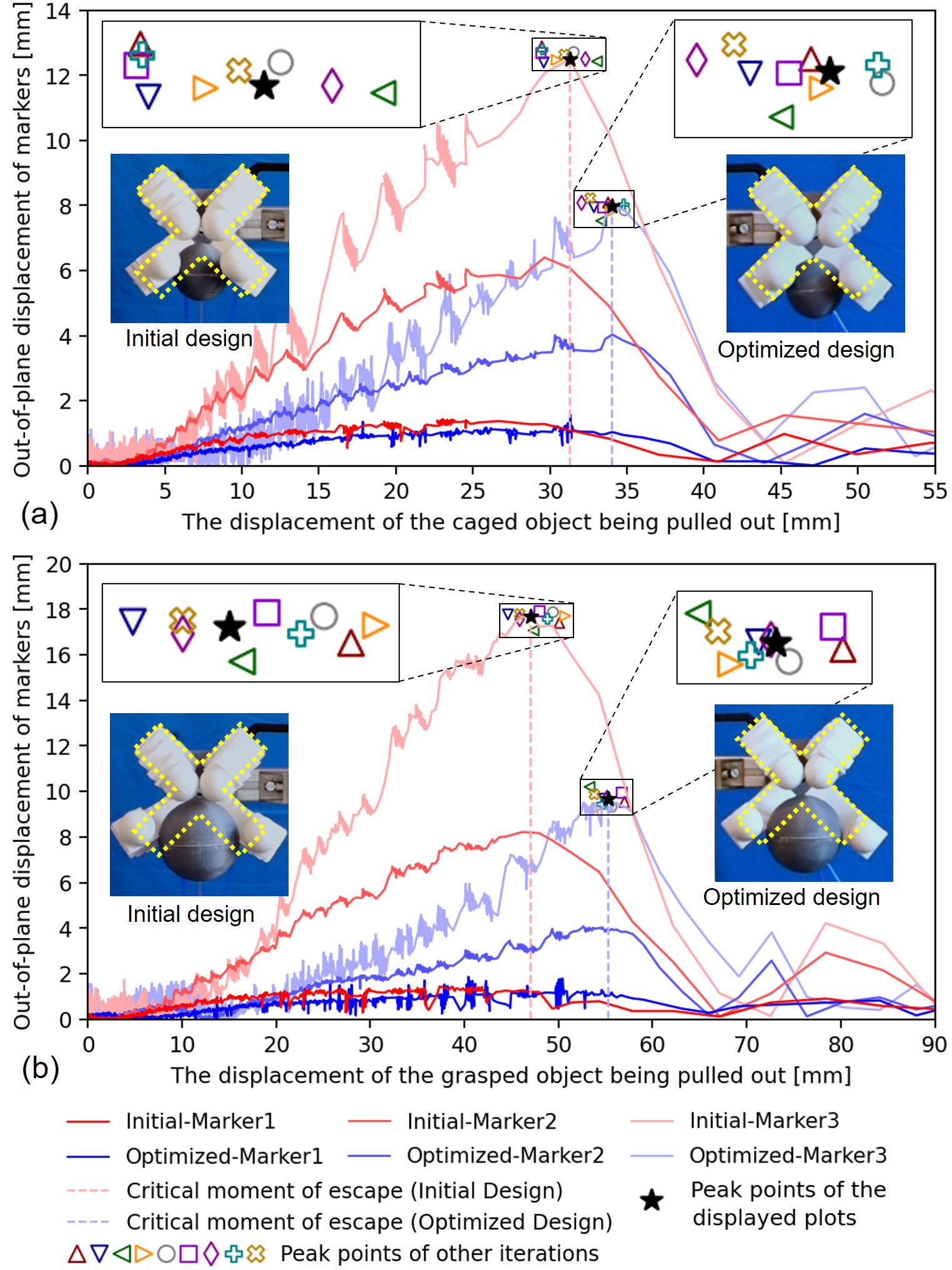
In physical tests, the displacement applied to the caged object is traced by markers attached to the string for pulling the object. The out-of-plane displacements of the 3 markers on the fingers are also tracked by the motion capture system. When the ball is pulled out, the relationship curves between the caged object’s displacement and the out-of-plane displacement can be plotted as in Fig.11(a). The same test was taken 10 times and the peak points from all tests are marked on the graph with different symbols. It can be observed that the optimized gripper will generate less out-of-plane deformation, which is especially noticeable on the marker near the fingertip (Marker 3) – i.e., the maximum out-of-plane displacement of the unoptimized gripper , on average, is about of the optimized one. If the stage before the Marker 3 reaches the peak is defined as ‘stable’ caging, we can find that the optimized soft gripper allows a much larger value on the object’s escape displacement under stable caging. A similar result can be obtained on the test with a larger sphere (Diameter: 70mm) under grasping – see Fig.11(b). For Marker 3, which is closer to the fingertip, the mean of maximum out-of-plane displacement of the unoptimized gripper is about of the optimized one. In short, both the caging and the grasping become more stable on the optimized gripper.
V-D Dynamic experiment
Another interesting study investigates the stability of grasping/caging under dynamic loads. Load in the form of instantaneous impact is an important reason for grasp failure. In this experiment, the impact resistance is compared between two designs. The grippers are first actuated to grasp/cage a sphere that is initially connected to a 0.5kg weight by an inextensible string. The weight does not apply any load to the sphere at the beginning of the experiment until we pull the trigger of the release mechanism (see the illustration in Fig.9(a)). When the weight falls from various heights , different momentum as will be applied to the grasped/caged sphere with being the mass of the weight. We compare the stability of a gripper by checking if the grasped/caged sphere will escape by applying different momentum as impact. Spheres with diameters of 50mm and 70mm are used for caging and grasping respectively.
As already shown in Fig.1, we used 78mm and 146mm as height for the caged sphere and the grasped sphere, respectively, which in fact applied 0.62 and 0.85 (Unit: ) as impact momentum to the spheres. With a fixed actuation pressure of 100kPa, ten repeated tests showed the same conclusion – the initial design is unable to hold the spheres while the optimized design can withstand the impact. The results of the comparison can also be found in the supplementary video.
VI Conclusions and Discussion
A data-driven framework is proposed in this paper to optimize the out-of-plane stiffness for soft grippers so that more stable grasping/caging can be realized while keeping their flexibility in bending. In this work, we first developed a new objective function quantitatively evaluate the out-of-plane stiffness under a fixed bending requirement. After that, we introduced a data-driven framework for optimizing the out-of-plane stiffness on parameterized gripper models by learning a differentiable function. Sensitivity analysis has been conducted on the parametric model of the SPBA design to determine the variables to be optimized with the help of Finite Element Analysis (FEA). The optimized design is finally computed by a gradient-based optimizer. The effectiveness of this method is demonstrated in the design of the soft pneumatic bending actuator (SPBA). Both FE simulations and physical experiments are conducted on a gripper with 4 fingers (each finger consists of 7 SPBA units) to verify the performance of our approach. The results are very encouraging as the optimized design outperforms the initial one under both quasi-static and dynamic loads.
The optimization result shows a design with 1) minimized gap – i.e., an increased value of when keeping the length of each unit fixed and 2) a connection part with wider and shorter cross-section – i.e., increased and reduced . Considering the connection part as a ‘beam’, the principle behind this optimization is that the evolution intends to generate a short and wider ‘beam’ with less height to resist lateral bending and twisting. The sensitivity analysis is conducted at the median of parameter’s range, which may not cover all possible variations although we did not find any issue by this simplification in our experiment. The focus of our work is based on the optimization of structure design when the materials are not allowed to change. However, for the design of actuators without large shape/geometry variation, such as Galloway design [2], changing the material stiffness is important to enhance the out-of-plane stiffness. Lastly, when a smaller gap (i.e., a larger ) and a thinner shell (i.e., a smaller ) are obtained on our optimized design, the bellows inflate and collide faster. The collision between inflated bellows leads to a larger bending angle under a given pressure.
References
- [1] R. B. Scharff, J. Wu, J. M. Geraedts, and C. C. Wang, “Reducing out-of-plane deformation of soft robotic actuators for stable grasping,” in IEEE International Conference on Soft Robotics, 2019, pp. 265–270.
- [2] K. C. Galloway, P. Polygerinos, C. J. Walsh, and R. J. Wood, “Mechanically programmable bend radius for fiber-reinforced soft actuators,” in International Conference on Advanced Robotics (ICAR), 2013, pp. 1–6.
- [3] F. Connolly, P. Polygerinos, C. J. Walsh, and K. Bertoldi, “Mechanical programming of soft actuators by varying fiber angle,” Soft Robotics, vol. 2, no. 1, pp. 26–32, 2015.
- [4] F. Chen, Y. Miao, G. Gu, and X. Zhu, “Soft twisting pneumatic actuators enabled by freeform surface design,” IEEE Robotics and Automation Letters, vol. 6, no. 3, pp. 5253–5260, 2021.
- [5] G. Dämmer, S. Gablenz, A. Hildebrandt, and Z. Major, “Design and shape optimization of polyjet bellows actuators,” in IEEE International Conference on Soft Robotics (RoboSoft), 2018, pp. 282–287.
- [6] F. Ilievski, A. D. Mazzeo, R. F. Shepherd, X. Chen, and G. M. Whitesides, “Soft robotics for chemists,” Angewandte Chemie, vol. 123, no. 8, pp. 1930–1935, 2011.
- [7] J. Brown and S. Sukkarieh, “Design and evaluation of a modular robotic plum harvesting system utilizing soft components,” Journal of Field Robotics, vol. 38, no. 2, pp. 289–306, 2021.
- [8] Y. Chen, S. Le, Q. C. Tan, O. Lau, F. Wan, and C. Song, “A lobster-inspired robotic glove for hand rehabilitation,” in IEEE International Conference on Robotics and Automation (ICRA), 2017, pp. 4782–4787.
- [9] Y. Chen, F. Wan, T. Wu, and C. Song, “Soft-rigid interaction mechanism towards a lobster-inspired hybrid actuator,” Journal of Micromechanics and Microengineering, vol. 28, no. 1, p. 014007, 2017.
- [10] Y. Chen, H. Chung, B. Chen, Y. Sun, et al., “A lobster-inspired bending module for compliant robotic applications,” Bioinspiration & Biomimetics, vol. 15, no. 5, p. 056009, 2020.
- [11] A. Lotfiani, H. Zhao, Z. Shao, and X. Yi, “Torsional stiffness improvement of a soft pneumatic finger using embedded skeleton,” Journal of Mechanisms and Robotics, vol. 12, no. 1, p. 011016, 2020.
- [12] J. Morrow, H.-S. Shin, C. Phillips-Grafflin, S.-H. Jang, J. Torrey, R. Larkins, S. Dang, Y.-L. Park, and D. Berenson, “Improving soft pneumatic actuator fingers through integration of soft sensors, position and force control, and rigid fingernails,” in IEEE International Conference on Robotics and Automation (ICRA), 2016, pp. 5024–5031.
- [13] M. Wang, B.-P. Lin, and H. Yang, “A plant tendril mimic soft actuator with phototunable bending and chiral twisting motion modes,” Nature communications, vol. 7, no. 1, pp. 1–8, 2016.
- [14] T. Wang, L. Ge, and G. Gu, “Programmable design of soft pneu-net actuators with oblique chambers can generate coupled bending and twisting motions,” Sensors and Actuators A: Physical, vol. 271, pp. 131–138, 2018.
- [15] M. Al-Rubaiai, T. Pinto, C. Qian, and X. Tan, “Soft actuators with stiffness and shape modulation using 3d-printed conductive polylactic acid material,” Soft robotics, vol. 6, no. 3, pp. 318–332, 2019.
- [16] F. Chen and M. Y. Wang, “Design optimization of soft robots: A review of the state of the art,” IEEE Robotics & Automation Magazine, vol. 27, no. 4, pp. 27–43, 2020.
- [17] S. A. Morin, S. W. Kwok, J. Lessing, J. Ting, R. F. Shepherd, A. A. Stokes, and G. M. Whitesides, “Elastomeric tiles for the fabrication of inflatable structures,” Advanced Functional Materials, vol. 24, no. 35, pp. 5541–5549, 2014.
- [18] A. E. Forte, P. Z. Hanakata, L. Jin, E. Zari, A. Zareei, M. C. Fernandes, L. Sumner, J. Alvarez, and K. Bertoldi, “Inverse design of inflatable soft membranes through machine learning,” Advanced Functional Materials, p. 2111610, 2022.
- [19] B. Mosadegh, P. Polygerinos, C. Keplinger, S. Wennstedt, R. F. Shepherd, U. Gupta, J. Shim, K. Bertoldi, C. J. Walsh, and G. M. Whitesides, “Pneumatic networks for soft robotics that actuate rapidly,” Advanced functional materials, vol. 24, no. 15, pp. 2163–2170, 2014.
- [20] A. Altelbani, H. Zhou, S. Mehrdad, F. Alambeigi, and S. F. Atashzar, “Design, fabrication, and validation of a new family of 3d-printable structurally-programmable actuators for soft robotics,” IEEE Robotics and Automation Letters, vol. 6, no. 4, pp. 7941–7948, 2021.
- [21] X. Ke, J. Jang, Z. Chai, H. Yong, J. Zhu, H. Chen, C. F. Guo, H. Ding, and Z. Wu, “Stiffness preprogrammable soft bending pneumatic actuators for high-efficient, conformal operation,” Soft Robotics, 2021.
- [22] H. Liu, Y.-S. Ong, and J. Cai, “A survey of adaptive sampling for global metamodeling in support of simulation-based complex engineering design,” Structural and Multidisciplinary Optimization, vol. 57, no. 1, pp. 393–416, 2018.
- [23] N. Cressie, “Spatial prediction and ordinary kriging,” Mathematical geology, vol. 20, no. 4, pp. 405–421, 1988.
- [24] C. E. Rasmussen, “Gaussian processes in machine learning,” in Summer school on machine learning. Springer, 2003, pp. 63–71.
- [25] N. Dyn, D. Levin, and S. Rippa, “Numerical procedures for surface fitting of scattered data by radial functions,” SIAM Journal on Scientific and Statistical Computing, vol. 7, no. 2, pp. 639–659, 1986.
- [26] S. M. Clarke, J. H. Griebsch, and T. W. Simpson, “Analysis of support vector regression for approximation of complex engineering analyses,” Journal of Mechanical Design, vol. 127, no. 6, pp. 1077–1087, 2005.
- [27] G. G. Wang and S. Shan, “Review of metamodeling techniques in support of engineering design optimization,” Journal of Mechanical Design, vol. 129, no. 4, pp. 370–380, 2007.
- [28] H.-S. Park and X.-P. Dang, “Structural optimization based on cad–cae integration and metamodeling techniques,” Computer-Aided Design, vol. 42, no. 10, pp. 889–902, 2010.
- [29] E. Acar, M. Guler, B. Gerceker, M. Cerit, and B. Bayram, “Multi-objective crashworthiness optimization of tapered thin-walled tubes with axisymmetric indentations,” Thin-Walled Structures, vol. 49, no. 1, pp. 94–105, 2011.
- [30] H. K. Yap, H. Y. Ng, and C.-H. Yeow, “High-force soft printable pneumatics for soft robotic applications,” Soft Robotics, vol. 3, no. 3, pp. 144–158, 2016.
- [31] I. M. Sobol’, D. Asotsky, A. Kreinin, and S. Kucherenko, “Construction and comparison of high-dimensional sobol’generators,” Wilmott, vol. 2011, no. 56, pp. 64–79, 2011.
- [32] H. Q. Dinh, G. Turk, and G. Slabaugh, “Reconstructing surfaces by volumetric regularization using radial basis functions,” IEEE transactions on pattern analysis and machine intelligence, vol. 24, no. 10, pp. 1358–1371, 2002.
- [33] G. Turk and J. F. O’brien, “Shape transformation using variational implicit functions,” in ACM SIGGRAPH 2005 Courses, 2005, pp. 13–es.
Appendix
A comprehensive visualization of the learned functions for and can be in Fig.12 together with Fig.7(b, c).