Magnetization dynamics in proximity-coupled superconductor-ferromagnet-superconductor multilayers. Part II.
Abstract
In this work, we the study magnetization dynamics in superconductor-ferromagnet-superconductor thin-film structures . Results of the broad-band ferromagnetic resonance spectroscopy are reported for a large set of samples with varied thickness of both superconducting and ferromagnetic layers in a wide frequency, field, and temperature ranges. Experimentally the one-dimensional anisotropic action of superconducting torque on magnetization dynamics is established; its dependence on thickness of layers is revealed. It is demonstrated that experimental findings support the recently-proposed mechanism of the superconducting torque formation via the interplay between the superconducting kinetic inductance and magnetization precession at superconductor-ferromagnet interfaces.
I Introduction
Advantages from hybridization of antagonistic superconducting and ferromagnetic orders in electronics and spintronics have been repeatedly demonstrated in past decades [1]. The interplay between ferromagnetic and superconducting spin orders enables manipulation with spin states and leads to a development of various electronic and spintronic elements, including superconductor-ferromagnet-superconductor (S-F-S) Josephson junctions [1, 2, 3], superconducting phase shifters [4, 5], memory elements [6, 7, 8], F-S-F–based spin valves [9, 10], Josephson diodes [11] and more complex long-range spin-triplet superconducting systems [12, 13, 14, 15, 16].
Recently application capabilities of S-F hybridization have been expanded by demonstrations of its prospects in magnonics. Magnonics is a growing field of research which offers approaches for the transfer and processing of information via spin waves. A good overview of various potential applications and recent advances in magnonics can be found in Refs. [17, 18, 19, 20, 21, 22, 23, 24] and references therein. In development of magnonic systems one of principle requirements is engineering of appropriate spin-wave dispersion.
Various wide-range manipulations with the spin-wave dispersion have been demonstrated at cryogenic temperatures when coupling magnonic systems with superconductors. For instance, interaction of a magnonic media with the superconducting vortex matter allows to form and tune forbidden bands at sub-micrometer wavelength which matches the parameter of the vortex lattice [25], or to excite exchange spin waves via driving the vortex lattice with the electric current [26]. Also, magnetostatic interaction of spin waves with superconducting Meissner currents in thin-film hybrid structures modifies substantially the spin-wave dispersion [27, 28] and can be used to form magnonic crystals [29] or to gate the magnon current [30]. Remarkably, low speed of electromagnetic propagation in superconductor-insulator-superconductor thin-film structures facilitates achievement of the ultra-strong photon-to-magnon coupling in on-chip hybrid devices [31, 32].
A striking phenomenon in S-F hybrid structures was reported recently in Ref. [33] and studied in more details in Ref. [34]. In superconductor-ferromagnet-superconductor trilayer thin-film structures a radical increase in the ferromagnetic resonance (FMR) frequency occurs in the presence of electronic interaction between superconducting and ferromagnetic layers. The phenomenon is strong: in some S-F-S structures the highest natural FMR frequencies are reached among in-plane magnetized ferromagnetic systems [34]. Intriguingly, so far, the mechanism behind the phenomenon remains unestablished.
In this work, we report a comprehensive experimental study of the phenomenon. We report results of FMR spectroscopy for a large set of samples with varied thickness of both superconducting and ferromagnetic layers in a wide frequency, field, and temperature ranges. We establish an anisotropic one-dimensional action of hybridization-induced torque acting on magnetization dynamics and the dependence of this superconducting torque on the magnetic field. Experimental results support the recently proposed model by M. Silaev [35], which explains the phenomenon in S-F-S structures as the outcome of the coupling between magnetization dynamics and superconducting kinetic inductance at S-F interfaces.
II Experimental details
| Sample ID | (Nb), nm | (Py), nm | (Nb), nm | , mT | , T | , mT | , K | |
| S1 | 110 | 10 | 110 | 1.5 | 1.051 | 31.8 | 8.74 | 3.79 |
| S2 | 120 | 11 | 120 | -3.3 | 1.029 | 39.1 | 8.56 | 3.70 |
| S3 | 110 | 19 | 110 | -0.15 | 1.100 | 78.8 | 8.90 | 3.48 |
| S4 | 100 | 35 | 100 | -0.2 | 1.132 | 163.6 | 8.92 | 3.80 |
| S5 | 140 | 45 | 174 | -0.4 | 1.18 | 193.7 | 9.08 | 4.90 |
| S6 | 110 | 120 | 110 | -0.1 | 1.123 | 352.6 | 8.82 | 4.56 |
| S7 | 110 | 350 | 110 | 1.6 | 1.076 | 617.2 | 8.74 | 8.89 |
| S8 | 41 | 24 | 41 | -0.2 | 1.131 | 37.8 | 7.51 | 3.07 |
| S9 | 200 | 30 | 50 | -1 | 1.146 | 96.8 | 8.74 | 4.38 |
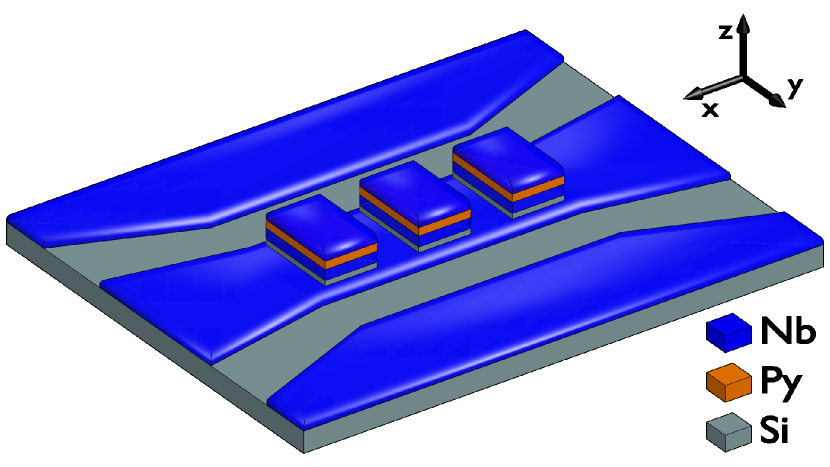
Magnetization dynamics in S-F-S structures is studied by measuring the ferromagnetic resonance absorption spectrum using the VNA-FMR approach [36, 37, 38, 39]. A schematic illustration of investigated samples is shown in Fig. 1. The chip consists of a thin-film superconducting niobium (Nb) co-planar waveguide with 50 Ohm impedance and 82-150-82 m center-gap-center dimensions and a series of niobium-permalloy(Py=Fe20Ni80)-niobium (Nb-Py-Nb) film structures with lateral dimensions m and spacing of 25 m along the axis that are placed directly on top of the central transmission line of the waveguide. Deposition of Nb-Py-Nb trilayers is performed in a single vacuum cycle ensuring the electron transparency at Nb-Py interfaces. Thin Si or AlOx spacing layer is deposited between Nb co-planar waveguide and the trilayers in order to ensure electrical insulation of the studied samples from the waveguide. As a result, a series of samples has been fabricated and measured with different thickness of superconducting (S) and ferromagnetic (F) layers (see Tab. 1).
Microwave spectroscopy of samples was performed by measuring the transmission characteristics in the closed-cycle cryostat Oxford Instruments Triton (base temperature 1.2 K) equipped with the home-made superconducting solenoid. Spectroscopy was performed in the field range from -0.22 T to 0.22 T, in the frequency range from 0 up to 20 GHz, and in the temperature range from 2 to 11 K. Magnetic field was applied in-plane along the direction of the waveguide in Fig. 1. FMR spectra at different temperatures were analysed by fitting characteristics at specified and with the Lorentz curve and, thus, obtaining the dependencies of the resonance frequency on magnetic field .
III Experimental results
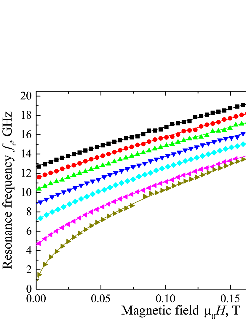
Figure 2 demonstrates the essence of the studied phenomenon: it shows dependencies of the FMR frequency on magnetic field for the S4 sample (see Tab. 1) which is used as the representative example. The S5 sample consists of 100 nm thick Nb layers and 35 nm thick Py layer. Upon decreasing the temperature below the critical temperature of Nb K the resonance curve shifts gradually to higher frequencies. For instance, upon decreasing the temperature the frequency of the natural FMR increases from about 0.5 GHz at K to about 13 GHz at K.
At FMR curves in Fig. 2 follow the typical Kittel dependence for thin in-plane-magnetized ferromagnetic films at in-plane magnetic field:
| (1) |
where is the vacuum permeability, Hz/T is the gyromagnetic ratio for permalloy, is the uniaxial anisotropy field that is aligned with the external field, and is the effective magnetization, which includes the saturation magnetization and the out-of-plane anisotropy field. For all studied samples the fit of FMR curves at with Eq. 1 yields negligible anisotropy field , the effective magnetization T, which is close to typical values of the saturation magnetization of permalloy T, and no noticeable dependence of and on temperature. Magnetic parameters and for all studied samples are provided in Tab. 1. The fit of curves for the S5 sample with Eq. 1 at temperature K is show in Fig. 2 with yellow solid line.
At FMR curves obey a different expression. In Refs. [34, 31] it was shown that technically by fitting at with Eq. 1 the action of superconductivity result in equal but different in sign uniaxial anisotropy field and changes of the effective magnetization : . Following the basics of derivation of the Kittel formula [40], this equality indicates that superconductivity acts on magnetization as the one-dimensional restoring torque along the axis in Fig. 1, and the fitting function should take the form , where is the field of the superconducting torque. A satisfactory fit with such expression can be obtained for all samples in Tab 1 at temperatures , while for the sample S8, which is based on thin superconducting layers with , this expression is valid in the entire temperature range. Here nm [31, 41] is the London penetration depth in bulk niobium at zero temperature
However, as was also shown in Refs. [34, 31] at temperatures the superconductivity-induced uniaxial anisotropy field in Eq. 1 no longer correspond to . As it appears, this discrepancy is a rather artificial effect and can be explained by suppression of the superconducting torque upon increasing the magnetic field. At higher fields suppression of the field result in reduction of the derivative from the curve. The fit of such resonance line with the conventional Kittel formula Eq. 1 result in larger reduction of the effective magnetization in comparison to the induced anisotropy at temperatures . We found that at FMR curves for all studied samples in Tab. 1 obey the modified Kittel dependence:
| (2) | ||||
where and are constants and are derived at (see Tab 1), is the field of one-dimensional superconducting torque at zero applied field, and the parameter reflects the dependence of the superconducting torque on applied magnetic field. We confirm that for all studied samples FMR curves at all temperatures can be fitted with Eq. 2. Examples of such fit are shown for the S4 sample in Fig. 2 with solid lines.
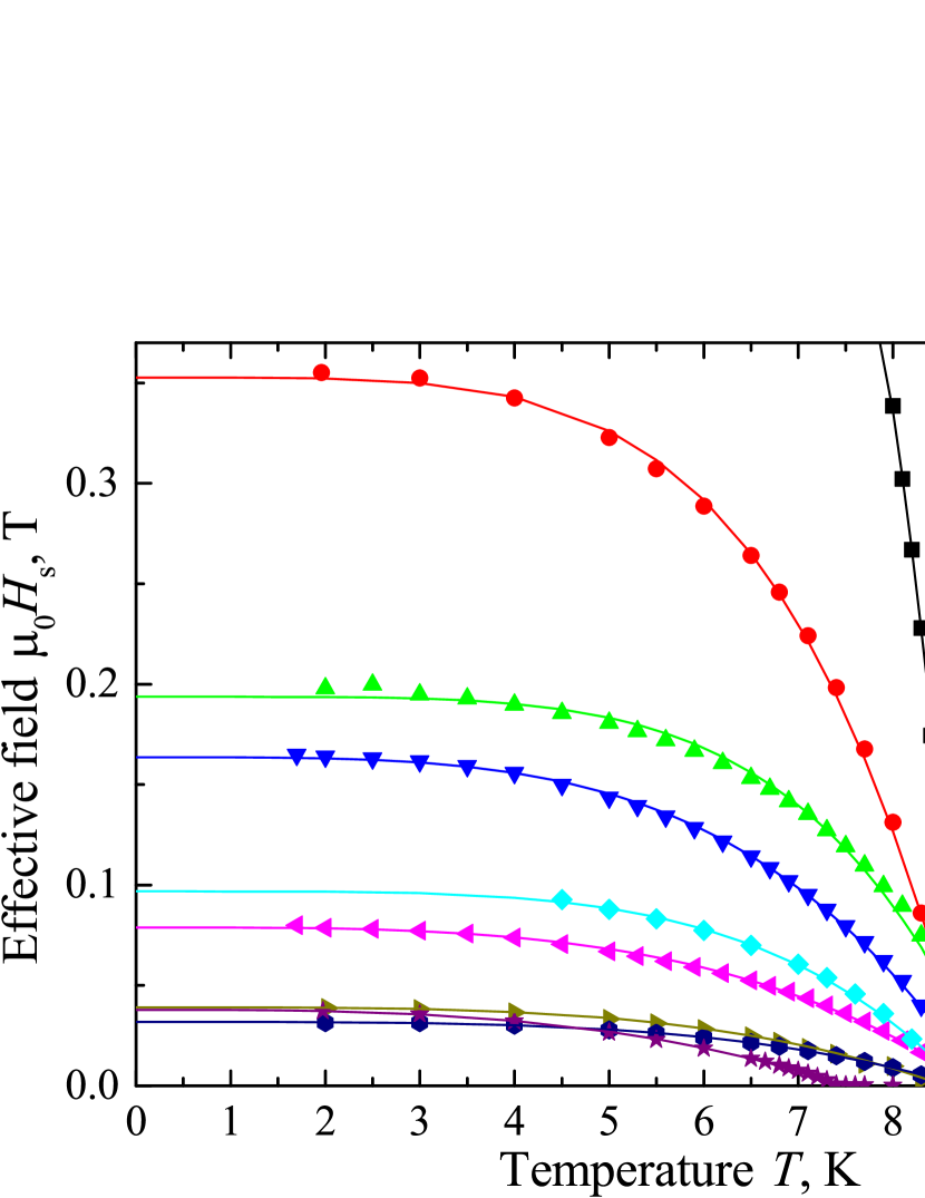
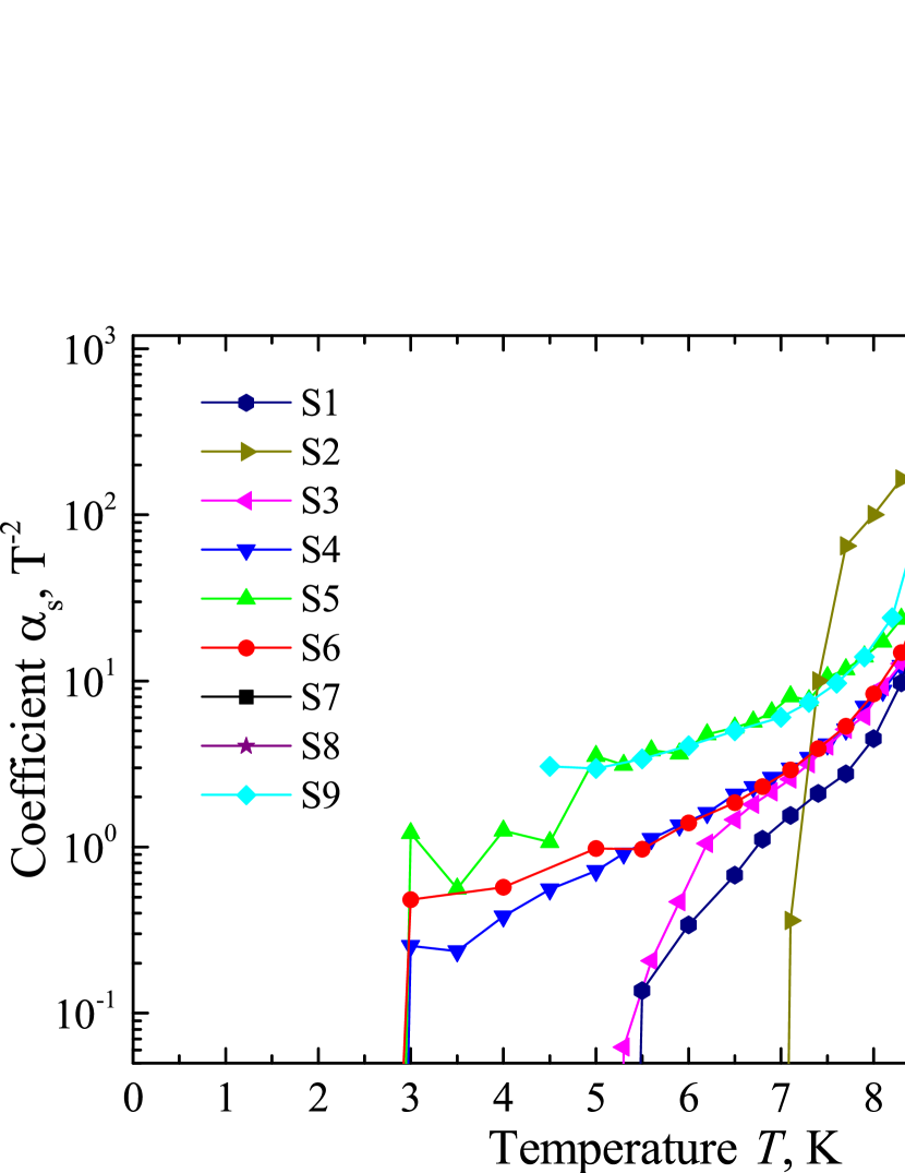
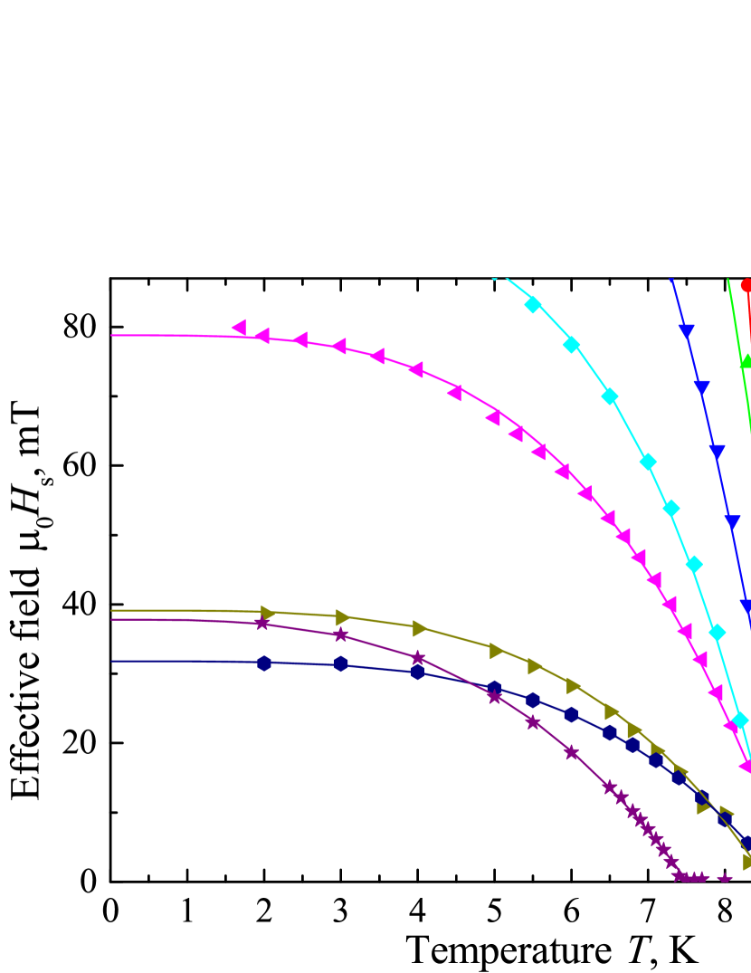
Analysis of resonance lines with Eqs. 1 and 2 yields dependencies of the superconducting torque field and of the field-dependence coefficient on temperature, and . This data is provided for all studied samples in Fig. 3a-c. Notice that for all samples except S8 and S7 the parameter growth exponentially from T-2 at K up to T-2 at K.
Temperature dependence of the torque field can be characterized by fitting it with the following expression [34]:
| (3) |
where is the superconducting spin-torque field at zero field and zero temperature, is the superconducting critical temperature of S-F-S trilayers, and is a free exponent parameter. The fit of with Eq. 3 for all samples is shown in Fig. 3a-b with solid lines and yields parameters and provided in Tab 1. Notice that for all samples except of the S7, which contains the the thickest F-layer, the exponent is in the range from about 3 up to 5 with the average value about 4. Also we notice that due to technical limitations resonance curves of S7 sample with the thickest F-layer could be measured only above to 8 K and the value of below 8 K are obtained via the extrapolation with Eq. 3. This extrapolation yields the natural FMR frequency in the S7 sample GHz at zero temperature in case if the value is correct, or GHz for (in the latter case T), which is the maximum value observed among the rest of samples in Tab. 1.
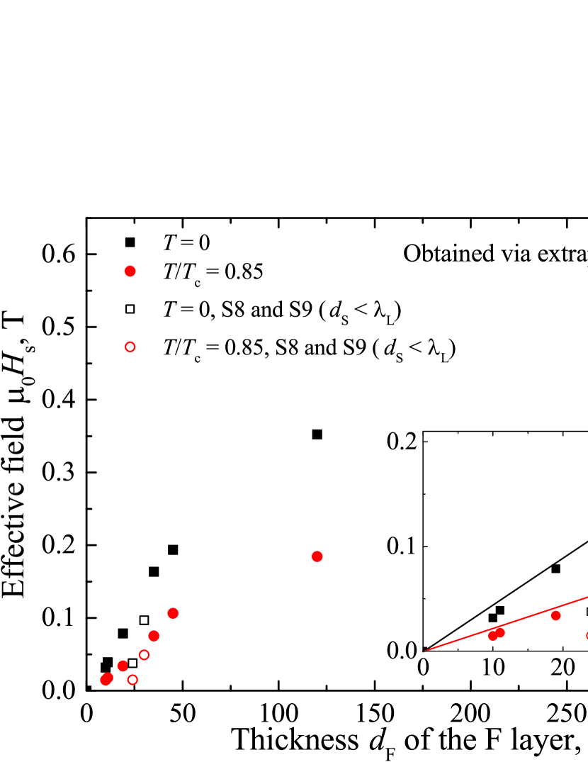
Figure 3d shows the dependence of the superconducting torque field on the thickness of ferromagnetic layer at zero temperature and at . This is the core result of this work. Figure 3d clearly demonstrates the overall logarithmic-like dependence of on thickness , with the linear growth of at low (see the inset in Fig. 3d) and retardation of growth at higher . Also, Fig. 3d reveals the dependence of the superconducting torque field on the thickness of superconducting layers: in case is the thickness of one of S-layers is reduced is also reduced (open symbols in Fig. 3d). Notice that while in case of the S8 sample this reduction can be partially explained by suppressed superconductivity and smaller K, this is not the case for the S9 sample where is comparable with values for the rest of samples.
IV Discussion
The original explanation of the phenomenon in S-F-S trilayers suggested the role of spin-polarized spin-triplet Cooper pairs in formation of the superconductivity-induced anisotropy via the spin-transfer-torque mechanism [33]. Yet, this mechanism requires the frequency of magnetization dynamics of the order of the superconducting gap [42], can hardly be expected in 350 nm thick junctions, and does not yield the one-dimensional torque on magnetic moment.
The first hint on inductive origin of the phenomenon in S-F-S trilayers was reported in Ref. [43] where the magnetostatic interaction has been considered between the screening currents induced by ferromagnetic stray fields in S-layers and the magnetic moment in the F-layer. While only the static case has been considered, it was shown that in case if superconducting currents are allowed to loop around the ferromagnetic layer additional DC demagnetising field is expected with the following dependence on magnetic and structural characteristics of trilayers
| (4) |
where is the London penetration depth and is the length of the structure. The theory in Ref. [43] provides an explanation for the one-dimensionality of the demagnetizing field along the -axis in Fig. 1 and predicts the growth of the demagnetizing field with increasing thickness of the F-layer. Yet, according to Eq. 4 this theory predicts a parabolic dependence of , which is inconsistent with Fig. 3d, and some dependence of on the length of the structure, which was not observed experimentally. In fact, this theory leads to a rather counter-intuitive outcome that the effect in S-F-S structures where superconducting currents are allowed to loop around the ferromagnetic layer should be measurable with conventional magnetization measurements.
The mechanism behind the superconducting torque in S-F-S trilayers was revealed in Ref. [35]. The mechanism implies the coupling of the superconducting kinetic inductance with the precessing magnetization at S-F interfaces and formation of macroscopic circulation currents curling around -axis in the opposite phase with precessing magnetization. The model in Ref. [35] predicts exactly the same dependence of the resonance frequency on the magnetic field as in Eq. 2 in the limit :
| (5) |
In fact, Eq. 5 demonstrates the linear dependence of the superconducting torque on thickness at small , which is consistent with Fig. 3d. The reduction of the superconducting torque upon increasing the magnetic field in Eq. 5 is explained by the increase of the penetration depth [41]: . The dependence of the superconducting torque on the thickness of S-layers is also captured in Eq. 5 as . Both effects are observed in Fig. 3d. At the model in Ref. [35] predicts the saturation of the superconducting torque to a constant value , which is also observed in Fig. 3d. Thus, the kinetic inductance origin behind the dramatic increase of the FMR frequency in S-F-S trilayers with electronic interaction at S-F interfaces is confirmed.
As a final remark, it can be expected that superconductivity in S-F-S structures modifies the dispersion of perpendicular standing spin waves (PSSW) [44, 45, 46, 47, 48]. In the case of closed PSSW boundary conditions [44, 45, 47] magnetization precession at both S-F interfaces does not take place and, thus, the superconducting torque is not formed. In the case of free PSSW boundary conditions [46, 48] magnetization at S-F interfaces precesses at opposite phases for even modes and precesses in-phase for odd modes, which corresponds to cancellation of the superconducting torque for even modes and its presence for odd modes, respectively. In the general case when the F-layers is magnetically non-uniform across its thickness [48] and the spin boundary conditions are affected by surface anisotropies [49, 50] the effect of the superconducting torue on the dispersion of PSSWs becomes non-trivial.
V Conclusion
Summarising, we report a comprehensive experimental study of magnetization dynamics in S-F-S trilayers. We report results of FMR spectroscopy for a large set of samples with varied thickness of both superconducting and ferromagnetic layers in a wide frequency, field, and temperature ranges. Experimentally we establish an anisotropic one-dimensional action of hybridization-induced torque acting on magnetization dynamics and the dependence of this superconducting torque on the magnetic field. Experimental results confirm the recently proposed model by M. Silaev [35], which explains the phenomenon in S-F-S structures as the outcome of the coupling between magnetization dynamics and superconducting kinetic inductance at S-F interfaces. Our results open wide prospects for application of the superconducting kinetic inductance in magnonics. In addition, as was suggested in Ref. [35], S-F-S systems provide the playground for Anderson-Higgs mass generation of boson quasiparticles in high-energy Standard Model and in condensed matter systems.
VI Acknowledgments
The authors acknowledge Dr. M. Silaev for fruitful discussions, critical reading of the manuscript and useful suggestions. The research study was financially supported by the Russian Science Foundation (grant N 22-22-00314).
References
- Linder and Robinson [2015] J. Linder and J. W. A. Robinson, Superconducting spintronics, Nat. Phys. 11, 307 (2015).
- Ryazanov et al. [2001] V. V. Ryazanov, V. A. Oboznov, A. Y. Rusanov, A. V. Veretennikov, A. A. Golubov, and J. Aarts, Coupling of two superconductors through a ferromagnet: Evidence for a pi-junction, Phys. Rev. Lett. 86, 2427 (2001).
- Weides et al. [2007] M. Weides, M. Kemmler, E. Goldobin, D. Koelle, R. Kleiner, H. Kohlstedt, and A. Buzdin, Appl. Phys. Lett. 89, 122511 (2007).
- Yamashita et al. [2020] T. Yamashita, S. Kim, H. Kato, W. Qiu, K. Semba, A. Fujimaki, and H. Terai, Scientific Reports 10, 13687 (2020).
- Feofanov et al. [2010] A. K. Feofanov, V. A. Oboznov, V. V. Bolginov, J. Lisenfeld, S. Poletto, V. V. Ryazanov, A. N. Rossolenko, M. Khabipov, D. Balashov, A. B. Zorin, P. N. Dmitriev, V. P. Koshelets, and A. V. Ustinov, Implementation of superconductor/ferromagnet/superconductor pi-shifters in superconducting digital and quantum circuits, Nat. Phys. 6, 593 (2010).
- Golovchanskiy et al. [2016a] I. A. Golovchanskiy, V. V. Bolginov, V. S. Stolyarov, N. N. Abramov, A. B. Hamida, O. V. Emelyanova, B. S. Stolyarov, M. Y. Kupriyanov, A. A. Golubov, and V. V. Ryazanov, Micromagnetic modeling of critical current oscillations in magnetic josephson junctions, Phys. Rev. B 94, 214514 (2016a).
- Vernik et al. [2013] I. V. Vernik, V. V. Bol’ginov, S. V. Bakurskiy, A. A. Golubov, M. Y. Kupriyanov, V. V. Ryazanov, and O. Mukhanov, Magnetic josephson junctions with superconducting interlayer for cryogenic memory, IEEE Trans. Appl. Supercond. 23, 1701208 (2013).
- Karelina et al. [2021] L. N. Karelina, R. A. Hovhannisyan, I. A. Golovchanskiy, V. I. Chichkov, A. B. Hamida, V. S. Stolyarov, L. S. Uspenskaya, S. A. Erkenov, V. V. Bolginov, and V. V. Ryazanov, J. Appl. Phys. 130, 173901 (2021).
- Gingrich et al. [2016] E. C. Gingrich, B. M. Niedzielski, J. A. Glick, Y. Wang, D. L. Miller, R. Loloee, W. P. P. Jr, and N. O. Birge, Nat. Phys. 12, 564 (2016).
- Lenk et al. [2017] D. Lenk, R. Morari, V. I. Zdravkov, A. Ullrich, Y. Khaydukov, G. Obermeier, C. Muller, A. S. Sidorenko, H.-A. K. von Nidda, S. Horn, L. R. Tagirov, and R. Tidecks, Full-switching fsf-type superconducting spin-triplet magnetic random access memory element, Phys. Rev. B 96, 184521 (2017).
- Jeon et al. [2022] K.-R. Jeon, J.-K. Kim, J. Yoon, J.-C. Jeon, H. Han, A. Cottet, T. Kontos, and S. S. P. Parkin, Nat. Mater. (2022).
- Robinson et al. [2010] J. W. A. Robinson, J. D. S. Witt, and M. G. Blamire, Controlled injection of spin-triplet supercurrents into a strong ferromagnet, Sci. 329, 59 (2010).
- Banerjee et al. [2014] N. Banerjee, J. Robinson, and M. Blamire, Reversible control of spin-polarized supercurrents in ferromagnetic josephson junctions, Nat. Comm. 5, 4771 (2014).
- Wang et al. [2010] J. Wang, M. Singh, M. Tian, N. Kumar, B. Liu, C. Shi, J. K. Jain, N. Samarth, T. E. Mallouk, and M. H. W. Chan, Interplay between superconductivity and ferromagnetism in crystalline nanowires, Nat. Phys. 6, 389 (2010).
- Glick et al. [2020] J. A. Glick, V. Aguilar, A. Gougam, B. M. Niedzielski, E. C. Gingrich, R. Loloee, W. P. P. Jr., and N. O. Birge, Sci. Adv. 4, eaat9457 (2020).
- Jeon et al. [2021] K.-R. Jeon, B. K. Hazra, K. Cho, A. Chakraborty, J.-C. Jeon, H. Han, H. L. Meyerheim, T. Kontos, and S. S. P. Parkin, Nat. Mater. 20, 1358 (2021).
- Chumak et al. [2022] A. Chumak et al., IEEE Trans. Magn. 58, 0800172 (2022).
- Pirro et al. [2021] P. Pirro, V. I. Vasyuchka, A. A. Serga, and B. Hillebrands, Nature Reviews Materials 6, 1114 (2021).
- Barman et al. [2021] A. Barman et al., J. Phys.: Condens. Matter 33, 413001 (2021).
- Chumak et al. [2015] A. V. Chumak, V. I. Vasyuchka, A. A. Serga, and B. Hillebrands, Nat. Phys. 11, 453 (2015).
- Lenk et al. [2011] B. Lenk, H. Ulrichs, and F. G. M. Munzenberg, The building blocks of magnonics, Phys. Rep. 507, 107 (2011).
- Csaba et al. [2017] G. Csaba, A. Papp, and W. Porod, Phys. Lett. A 381, 1471 (2017).
- Serga et al. [2010] A. A. Serga, A. V. Chumak, and B. Hillebrands, Yig magnonics, J. Phys. D: Appl. Phys. 43, 264002 (2010).
- Kruglyak et al. [2010] V. V. Kruglyak, S. O. Demokritov, and D. Grundler, Magnonics, J. Phys. D: Appl. Phys. 43, 264001 (2010).
- Dobrovolskiy et al. [2019] O. V. Dobrovolskiy, R. Sachser, T. Bracher, T. Fischer, V. V. Kruglyak, R. V. Vovk, V. A. Shklovskij, M. Huth, B. Hillebrands, and A. V. Chumak, Magnon-fluxon interaction in a ferromagnet/superconductor heterostructure, Nat. Phys. 15, 477 (2019).
- Dobrovolskiy et al. [2021] O. V. Dobrovolskiy, Q. Wang, D. Y. Vodolazov, B. Budinska, R. Sachser, A. V. Chumak, M. Huth, and A. I. Buzdin, arXiv , 2103.10156 (2021).
- Golovchanskiy et al. [2018a] I. A. Golovchanskiy, N. N. Abramov, V. S. Stolyarov, V. V. Bolginov, V. V. Ryazanov, A. A. Golubov, and A. V. Ustinov, Adv. Funct. Mater. 28, 1802375 (2018a).
- Golovchanskiy et al. [2018b] I. A. Golovchanskiy, N. N. Abramov, V. S. Stolyarov, V. V. Ryazanov, A. A. Golubov, and A. V. Ustinov, Modified dispersion law for spin waves coupled to a superconductor, J. Appl. Phys. 124, 233903 (2018b).
- Golovchanskiy et al. [2019] I. A. Golovchanskiy, N. N. Abramov, V. S. Stolyarov, P. S. Dzhumaev, O. V. Emelyanova, A. A. Golubov, V. V. Ryazanov, and A. V. Ustinov, Ferromagnet/superconductor hybrid magnonic metamaterials, Adv. Sci. 6, 1900435 (2019).
- Yu and Bauer [2022] T. Yu and G. E. W. Bauer, arXiv , 2201.09532 (2022).
- Golovchanskiy et al. [2021a] I. A. Golovchanskiy, N. N. Abramov, V. S. Stolyarov, M. Weides, V. V. Ryazanov, A. A. Golubov, A. V. Ustinov, and M. Y. Kupriyanov, Science Advances 7, eabe8638 (2021a).
- Golovchanskiy et al. [2021b] I. A. Golovchanskiy, N. N. Abramov, V. S. Stolyarov, A. A. Golubov, M. Y. Kupriyanov, V. V. Ryazanov, and A. V. Ustinov, Physical Review Applied 16, 034029 (2021b).
- Li et al. [2018] L.-L. Li, Y.-L. Zhao, X.-X. Zhang, and Y. Sun, Possible evidence for spin-transfer torque induced by spin-triplet supercurrents, Chin. Phys. Lett. 35, 077401 (2018).
- Golovchanskiy et al. [2020] I. A. Golovchanskiy, N. N. Abramov, V. S. Stolyarov, V. I. Chichkov, M. Silaev, I. V. Shchetinin, A. A. Golubov, V. V. Ryazanov, A. V. Ustinov, and M. Y. Kupriyanov, Phys. Rev. Appl. 14, 024086 (2020).
- Silaev [2022] M. A. Silaev, Anderson-higgs mass of magnons in superconductor/ferromagnet/superconductor systems, arXiv:2207.13201 (2022).
- Neudecker et al. [2006] I. Neudecker, G. Woltersdorf, B. Heinrich, T. Okuno, G. Gubbiotti, and C. Back, Comparison of frequency, field, and time domain ferromagnetic resonance methods, J. Magn. Magn. Mat. 307, 148 (2006).
- Kalarickal et al. [2006] S. S. Kalarickal, P. Krivosik, M. Wu, C. E. Patton, M. L. Schneider, P. Kabos, T. J. Silva, and J. P. Nibarger, Ferromagnetic resonance linewidth in metallic thin films: Comparison of measurement methods, J. Appl. Phys. 99, 093909 (2006).
- Chen et al. [2007] Y.-C. Chen, D.-S. Hung, Y.-D. Yao, S.-F. Lee, H.-P. Ji, and C. Yu, Ferromagnetic resonance study of thickness-dependent magnetization precession in ni80fe20 films, J. Appl. Phys. 101, 09C104 (2007).
- Golovchanskiy et al. [2016b] I. A. Golovchanskiy, V. V. Bolginov, N. N. Abramov, V. S. Stolyarov, A. B. Hamida, V. I. Chichkov, D. Roditchev, and V. V. Ryazanov, J. Appl. Phys. 120, 163902 (2016b).
- Stancil [1993] D. Stancil, Theory of Magnetostatic Waves (Springer-Verlag New York, Inc., 1993).
- Gubin et al. [2005] A. I. Gubin, K. S. Ilin, S. A. Vitusevich, M. Siegel, and N. Klein, Physical Review B 71, 064503 (2005).
- Houzet [2008] M. Houzet, Ferromagnetic josephson junction with precessing magnetization, Phys. Rev. Lett. 101, 057009 (2008).
- Mironov and Buzdin [2021] S. V. Mironov and A. I. Buzdin, Appl. Phys. Lett. 119, 102601 (2021).
- Kittel [1958] C. Kittel, Physical Review 100, 1295 (1958).
- Seavey and Tannenwald [1959] M. H. Seavey and P. E. Tannenwald, Journal of Applied Physics 30, S227 (1959).
- Sparks [1970] M. Sparks, Phys. Rev. B 1, 3831 (1970).
- Klingler et al. [2015] S. Klingler, A. V. Chumak, T. Mewes, B. Khodadadi, C. Mewes, C. D. O. S. B. Hillebrands, and A. Conca, J. Phys. D: Appl. Phys. 48, 015001 (2015).
- Golovchanskiy et al. [2022] I. A. Golovchanskiy et al., Phys. Rev. Materials 6, 064406 (2022).
- Bajorek and Wilts [1971] C. H. Bajorek and C. H. Wilts, Journal of Applied Physics 42, 4324 (1971).
- Puszkarski [1979] H. Puszkarski, Prog. Surf. Sci. 9, 191 (1979).