22email: denis.bernard@in2p3.fr and
Stanley D. Hunter 33institutetext: NASA/Goddard Space Flight Center, Greenbelt Road, Greenbelt, MD 20771, USA
33email: stanley.d.hunter@nasa.gov and
Toru Tanimori 44institutetext: Graduate School of Science Kyoto University, Kyoto, Japan 606-8502,
44email: tanimori.thoru.6ekyoto-u.ac.jp
Time projection chambers for gamma-ray astronomy
Abstract
The detection of photons with energies greater than a few tenths of an MeV, interacting via Compton scattering and/or pair production, faces a number of difficulties. The reconstruction of single-scatter Compton events can only determine the direction of the incoming photon to a cone, or an arc thereof and the angular resolution of pair-conversion telescopes is badly degraded at low energies. Both of these difficulties are partially overcome if the density of the interaction medium is low. Also no precise polarization measurement on a cosmic source has been obtained in that energy range to date. We present the potential of low-density high-precision homogeneous active targets, such as time-projection chambers (TPC) to provide an unambiguous photon direction measurement for Compton events, an angular resolution down to the kinematic limit for pair events, and the polarimetry of linearly polarized radiation.
1 Keywords
Gas time-projection chamber (TPC), Compton scattering, pair conversion, point spread function, micropattern gas detector (MPGD), electron-tracking Compton camera (ETCC), polarization
2 Introduction
Gamma-ray astronomy proceeds by the analysis of the conversion of individual photons with an atom of a telescope, either
-
•
the Compton scattering on an electron, , in the approximate energy range , or
-
•
by the creation of an pair ( “nuclear” conversion, above a threshold ; “triplet” conversion, ), where is the electron mass.
At lower energies, X-rays are detected via their photo-electric interaction with matter, see Volume 1 of this Handbook.
A number of detector techniques have been developed (see Chapter Telescope concepts in gamma-ray astronomy in Vol. 2, Sect. IV), among which some use an homogeneous active target, that is, a device in which the photon converts and the trajectory of the charged particle(s) in the final state (electron and/or positron) are measured, that consists of an homogeneous medium. Among these, a TPC (time projection chamber) (Marx and Nygren, 1978) is a device in which a chunk of matter is immersed in an electric field; charged particles ionize the atoms/molecules on their way through the detector, after which the produced electrons and positive ions drift in the electric field towards an anode and a cathode, respectively, where their arrival creates an electric signal that can be measured. The collecting anode can be segmented in a two-dimensional (2D) series of pads, or in a two-fold set of strips, something which provides a 2D image of the flow of electrons that are “falling” on the anode at a particular time. The measurement of the drift duration provides the third coordinate: the collection and the analysis of these images as a function of time provides a full, 3D, picture of the charged particles in the final state for the particular event of the conversion of the photon.
For gases, the amount of charge produced by ionization is small, typically tens to hundreds of electrons per , so an amplification in the gas is needed, that was performed with multi-wire proportional chambers (MWPC), that have later been replaced by micropattern gas detectors (MPGD) such as micromegas (Giomataris et al., 1996), gas electron multiplier (GEM) (Sauli, 1997) or micro-pixels (Ochi et al., 2000).
For two-track final states, in the case of a two-fold series of strips, reconstructing the full 3D image of the event requires solving a two-fold ambiguity (i.e. the matching of either of two tracks in the () plane to either of two tracks in the () plane) something that is made easy (Fig. 11 of (Bernard et al., 2014)) by the violent variation of the energy deposited along the track, the distribution of which presents a large tail at high values (the Landau distribution). The ambiguity can also be solved with a three-fold series of strips, for example at 120 °of each-other, in a configuration known as .
In contrast with MWPCs for which the wire pitch is limited to values larger than a couple of millimeters, the collecting structure of MPGDs can be much smaller, enabling spatial resolutions down to (Thers et al., 2001).
In addition to measuring precisely the geometry of the conversion, TPCs can also provide precise measurements of the energy deposition in the gas, something which is key to high-precision Compton scattering, and of the energy deposition per unit length, , which enables the rejection of cosmic-ray ions, as is proportional to (Eq. (34.5) of (Zyla et al., 2020)). The TPC concept proves to be particularly powerful for the polarimetry of the incoming radiation, see Chapter: Time projection for polarimetry in Sec. II of Vol. 1 (X-rays) and Chapter: Design of gamma-ray polarimeters in Sec. IV of Vol. 2. Reviews on TPCs can be found in Sec. 35.6.5 (gas TPCs) and in Sec. 36.4 (liquid TPCs) of (Zyla et al., 2020) and in (Hilke, 2010; Fujii, 2014). The transport of electric charges in matter, drift detectors and their use is described in (Sauli, 1977; Blum and Rolandi, 2008; Sauli, 2014), the simulation of gas detectors can be performed by the Garfield++ software package (Veenhof, 1998) and the RD51 Collaboration (RD51, 2008) is coordinating the efforts of the community to develop gas detector technologies. Various configurations have been developed to meet various needs, such as “cartesian” TPCs (uniform electric field, e.g. (Atwood et al., 1991)), “radial” TPCs (e.g. (Obertelli et al., 2014)) and “spherical” TPCs (e.g. (Giomataris et al., 2008)).
TPCs are mainly used as inexpensive (in terms of the number of electronics channels) hyper-high-granularity trackers for low (Hz to kHz) rate experiments, due to the duration of the drift (microseconds for the electrons to milliseconds for the ions), as most users wish to avoid event pile-up. The TPC itself, though, can cope easily with much higher rates (e.g. a annihilation rate of 20 MHz (Fabbietti et al., 2011; Ball et al., 2012)), as long as the electric charge of the ion back-flow does not disturb the electric field, in which case gating the amplification device is advised (Nemethy et al., 1983). The complexity load is then transferred to the event-reconstruction software (See Fig. 13 of (Rauch, 2012)). It should be noted that most of the positive ions are created in the amplification volume of the MPGD and that in the case of the micromegas and of the GEM, a large fraction of them is collected by the grid, and therefore does not escape to the drift volume, something that limits the induced nuisance.
An important limitation of TPCs in their use for high-energy-physics (HEP) is their reliance on the information provided by other sub-detectors to build a trigger, and in particular to define the start time of the drift. Difficulties in obtaining a sufficiently large background noise rejection factor can induce Data Acquisition (Daq) dead time, and lead to a severe reduced trigger efficiency, as observed for example during the balloon test flight of the Liquid Xenon Gamma-Ray Imaging Telescope (LXeGRIT) TPC prototype (Curioni et al., 2007). For a stand-alone TPC in space, a trigger-less, continuous, autonomous mode (Rauch, 2012; Hunter et al., 2014) can be considered.
Dielectric gases that allow the free drift of injected electric charges, such as noble gases or alkanes, can be used, that have negligible electron attenuation over drift lengths of several meters. As electro-negative impurities in the gas can trap drifting electrons, maintaining a good gas purity on the long term is important. For example, the degradation of the gas in the EGRET spark chambers required regular gas changes and caused the instrument to be operated only intermittently in the later part of the Compton Gamma Ray Observatory mission (Esposito et al., 1999). Actually the dose rate of ionizing radiation that is inducing the production of these deleterious chemical species is much lower in orbit than in detectors on HEP experiments, and spark chambers are well known to be very powerful quencher polymerizing devices. Using the HARPO TPC prototype, that includes a number of elements that are potentially harmful to the gas purity (PVC, epoxy ..) continuous, perfectly stable operation was demonstrated for over six months just filtering out the oxygen contamination (Frotin et al., 2018). The test of a TPC prototype designed using high-vacuum technology for the Gravity and Extreme Magnetism Small Explorer (GEMS) X-ray polarimeter Instrument (XPI) demonstrated a gas-fill estimated lifetime larger than 23 years (Hill et al., 2013); they estimated the integrated charge expected on a space mission to be of the order (Hill et al., 2013). This can be compared to the performance of micromegas and GEM devices for LHC detectors, that can stand (which corresponds to ) without degradation (Titov, 2004), though with flushing some amount of fresh gas. A gas purifier system for the close-loop operation of Resistive Plate Chambers (RPC) at the LHC, with high recirculation fractions, has shown stable operation up to an integrated charge of (Capeans et al., 2013)). Alkanes can be replaced by CO2 to alleviate the polymerization issue. In that case, at extreme irradiation doses, the next contaminant of concern is found to be silicone, in particular from pump-oil outgassing (see, e.g., (Zimmermann and Cernoch, 2004)). Despite the huge body of knowledge accumulated on ageing of detectors exposed to extreme irradiation doses (but with some amount of fresh gas flushing), or sealed detectors in operation for an extended duration (but without an irradiation dose rate commensurate with that on a space mission), it is fair to state that a smooth decade-long operation of a sealed (possibly with recirculation and filtering) proportional gas detector exposed to an appropriate level of ionizing radiation is still to be demonstrated.
MPGDs are prone to sparking, especially when exposed to a charged-particle beam, with a rate that increases with the applied amplification voltage. The limiting mechanism was understood after it was observed that the spark production rate is much larger from a pion beam than from a muon beam of similar energy and intensity (Thers et al., 2001): hadrons can undergo hadronic interactions with the atoms of the detectors, after which a nuclear fragment can deposit a huge amount of energy in a very small volume at the end of its trajectory, due to the variation of (the Bragg peak) (Zyla et al., 2020). The phenomenon is particularly prevalent for micromegas, for which the transverse size of the avalanche is small, of the order of , and/or when a magnetic field is applied, that clamps the transverse diffusion of the drifting electrons. The problem is now routinely solved using an additional resistive layer (Alexopoulos et al., 2011).
3 Charged particles production and transport in a medium
3.1 Ionization
The average energy lost by a charged particle traversing a piece of matter is described by the Bethe equation (eq. (33.5) of (Zyla et al., 2020)), that shows a sharp rise proportional to at low energies, a minimum at about and a slow rise at higher energies ( is the particle velocity normalized to that of light and is its Lorentz factor). The specific loss rate at the minimum (MIP, minimum ionizing particle) is proportional to and is therefore approximately independent of the nature of the gas, at , where , and are the density, the atomic number and the mass number of the target (Tab. 6.1 of (Zyla et al., 2020)), and is the electric charge of the particle normalized to the charge of an electron. Part of the interactions results in the ionization of the atoms, with an effective energy lost per produced electron of 20 to 40 eV (Tab. 1 of (Sauli, 1977)).
3.2 Drift, diffusion
As the ionization electrons drift in the electric field of the TPC, they undergo elastic collisions with the atoms and molecules of the gas, a process by which they lose some of their kinetic energy and by which they are deflected. Between two collisions, the electrons are accelerated in the field and follow a ballistic trajectory.
At low electric fields, the resulting average drift velocity, , is proportional to the electric field, , with typical values of the mobility of for most positive ions (Tab. 4 of (Sauli, 1977)), and for electrons, where is the gas pressure. On average, the deflections result in an isotropic, Gaussian-distributed spread of the distribution of the electron position that is named diffusion, with an RMS along any of the three directions of space with , where and are the duration and the length of the drift and is the diffusion coefficient (Sauli, 1977):
| (1) |
The spread can also be expressed as where : the low-field RMS spread is independent on the material used: at a given temperature, the only way to decrease is to increase the electric field.
At high electric fields, the rise of the electron drift velocity with the electric field saturates, the electron velocity distribution is characterized by a temperature that is larger than the ambient, and the diffusion process becomes anisotropic, with a diffusion coefficient in the transverse plane and in the longitudinal direction that differ increasingly at higher field. In pure argon, for example, the spread would amount to at while the thermal limit at 300 K at that field is .
Therefore a (usually small) fraction of multi-atomic (means here 2 atoms) molecular gas is added. These molecules have vibration and rotation degrees of freedom that enlarge the cross section of inelastic interactions from fast electrons, something which “cools” the electron bunch, and also they have absorption bands that mitigate the potentially catastrophic discharges induced by photo-electric effect on the detector cathode by impacts of avalanche-created U.V. photons – hence their appellation of “quenchers”.
Most gas TPCs use a mixture based on a large fraction of a noble gas together with a multi-atom molecular quencher (example an alkane). These “fast gases” allow at the same time a high electron-drift velocity of several and a small diffusion coefficient. For argon-isobutane mixtures, for example, the transverse coefficient plateaus above at a value that is proportional to , where is the quencher partial pressure (e.g. for a 4-bar 90:10 mix). In these conditions, the longitudinal coefficient is a smoothly decreasing function of , with little dependence on the quencher fraction and gas pressure, and amounts to for 4-bar 90:10 at ). It should be noted that some amount of diffusion, with a spread commensurate with the pitch size of the signal collection segmentation, enables the optimization of the spatial resolution of individual measurements (Fig. 7 of (Arogancia et al., 2009)). Charge amplification can be easily performed in these gases with gains of several (Attié, 2009; Veenhof, 2010) in current MPGD structures such as a multi-layer GEM (Sauli, 1997) or a micromegas (Giomataris et al., 1996).
3.3 Negative Ion Technique
Another option to reduce the diffusion of a TPC is to add a mildly electronegative component to the TPC gas. This is referred to as the negative ion (NI) technique, developed for TPC dark matter searches, which originally used carbon disulfide (CS2) (Martoff et al., 2000) (Martoff et al., 2005). Subsequently, nitromethane (CH3NO2) was also used (Martoff et al., 2009). The NI technique has been used in several different applications (Snowden-Ifft et al., 2003) (Son et al., 2010).
In the gas of a negative ion TPC (NI TPC), the NI component scavenges the free, ionization, electrons, within of their point of origin, to form negative ions, which then drift in the TPC gas. Compared to the electrons, which drift at super-thermal speed, the negative ions, being much more massive, remain in thermal equilibrium with the gas molecules and drift at the thermal velocity of the gas. Consequently, the diffusion of the NIs is reduced to the thermal diffusion limit, see Figure 6 in (Dion et al., 2011).
The NI technique reduces the diffusion coefficient to the thermal limit of , but at the cost of a much lower drift velocity (Hunter, 2018). This velocity is three to four orders of magnitude smaller than for electrons in a typical fast TPC gas (Peisert and Sauli, 1984). This slow velocity can make the detector more susceptible to background pile up. However, the high granularity of a TPC and the reduced diffusion and slow drift velocity allow image processing techniques to be employed to differentiate the high-energy photons interacting to produce electron pairs from the Compton low-energy recoil electrons produced by sub-MeV photons and cosmic ray tracks. Software techniques have been explored to address this problem (Garnett et al., 2021). Application of the negative ion technique to the Advanced Energetic Pair Telescope, and software solutions to deal with the slow drift velocity, is discussed in Subsection 5.2.
3.4 Energy measurements
Gas TPCs are thin detectors from which high-energy electrons escape (1 MeV electrons have an range in most gases (Berger et al., 2010a), e.g. 3.6 m in 1-bar argon). Also, the measurement of the track momentum by the analysis of the multiple deflections induced by multiple scattering in the detector, which is a powerful method for denser detectors, is too imprecise for gas TPCs (Frosini and Bernard, 2017). So it is difficult to measure the energy of the leptons, and therefore of the candidate photon, from the TPC alone.
Either the TPC can be immersed in a magnetic field, to become a high-precision magnetic spectrometer, or the TPC can be complemented with an additional detector that either measures the momentum of the track(s), such as a transition-radiation detector (TRD) (Wakely et al., 2004) or the total energy of the final state, such as a calorimeter.
3.5 Magnetic field
Most gamma-ray telescopes on space missions do not include a magnetic spectrometer. The AMS experiment on the ISS does (Bourquin, 2005), however, and has a sensitivity to gamma rays (Beischer, 2020). The presence of a magnetic field has important consequences on the performances of the detector;
-
•
In the first place, the curvature enables a measurement of track momenta;
-
•
Also, low-momentum electrons are clamped to spiral and deposit their energy in a small volume, something that can help the trigger system survive the large Compton-induced single-track background;
-
•
Spiraling electrons might be an issue though, for the correct tracking of low-energy electrons in a Compton camera;
-
•
The transverse diffusion of the drifting electrons is greatly reduced, as the ballistic flight between collisions is along spiraling helices instead of parabolas.
-
•
Last but not least, at very high electron momenta where multiple scattering can be neglected, in the presence of a non-zero magnetic field, , the track fit includes a track curvature while for a straight line is fitted. The non-zero correlation between the curvature and the angle of the track at vertex induces a degradation of the single-track angle resolution of a factor of 4 with respect to the fit that assumes (compare, for example, eqs. (5) and (9) of (Regler and Fruhwirth, 2008)).
3.6 Absolute time measurement
The ability to measure precisely the absolute time of a gamma-ray conversion can be of interest, for example for pulsars or for transients. MPGD are fast devices, that enable event-time measurements with a precision of a couple of nanoseconds with a suitable electronics for tracks that are crossing them. This could allow building a trigger from a telescope consisting of a 3D set of individual TPC modules (Bernard et al., 2014), by forming multi-module coincidences.
For events for which the track(s) exit(s) by the side of the TPC without crossing the amplification structure, the degenerescence between the start time and the vertical position of the event in the TPC fundamental relation, , makes it difficult to determine separately the vertex vertical position and the conversion time. In these cases, the variation with drift time of the track width due to diffusion-induced spread enables a measurement (Antochi et al., 2021), though with a much degraded resolution.
4 Electron-Tracking Compton Camera with Gaseous Time-Projection Chamber
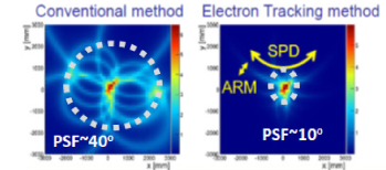
The simplest Compton telescopes are based on the analysis of one-scatter events, , after which the scattered photon propagates in the detector until it is absorbed: the position and the energy of the scattered electron and photon are measured, and the properties of the incident photon are inferred from this information. With that method, the direction of the incident photon is found to lie on a cone, something which makes the analysis of an extended field of view containing several sources complicated.
In more elaborate telescopes, the direction of propagation of the recoiling electron is tracked, so that the cone is reduced to an arc, something that simplifies the image analysis (Fig. 1 left).
The present Section addresses the extreme case for which the tracking of the electron is so precise that the analyst can use a bijection between the measured observables for a given Compton scatter event and the direction of the incoming photon (one-to-one mapping, Fig. 1 right), in a scheme that is named ETCC (electron-tracking Compton camera) (Tanimori et al., 2004, 2015, 2017). We will see that a low-density high-precision active target, such as a gas TPC, is well suited for that purpose.
4.1 How to realize complete bijection imaging for MeV gamma rays
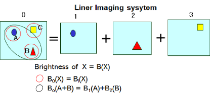
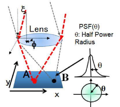
In astronomical imaging, the intensity of each point in the image is independent, and linearity is preserved, as shown in Fig. 2. This is the minimum requirement for maintaining quantitativeness in image analysis in general. Quantitative imaging is an essential technology, e.g., in radio and X-rays, because the electromagnetic waves can generally be refracted and reflected, as well as simply focused according to optical principles using a reflector and a lens. As shown in Fig. 3, reflectors and lenses make a bijection to each point on the image surface while preserving the intensity of rays in each direction at a size larger than the point spread function (PSF). Therefore, the intensity of each point separated from the PSF of the image is guaranteed to be linear, and the intensity can be accurately measured. The PSF is defined as the minimum angular distance that guarantees linearity. Here, we use a half-power angular radius (degrees) as the PSF. The linear optical system is shown in Fig. 2.
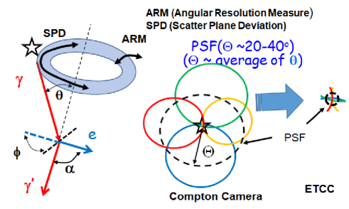
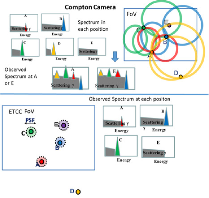
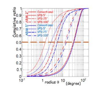
However, gamma rays have strong quantum properties, and refraction/reflection cannot be used. Therefore, the only way to determine the direction of the incident gamma ray is to solve the kinematics of Compton scattering for each gamma ray. This was attempted using a CC, starting in the 1970s. However, because the CC solves the equation of motion of Compton scattering incompletely owing to the lack of the direction of the recoil electron, only the elevation angle in the arrival direction can be obtained, as shown in Fig. 4. Therefore, the gamma-ray direction is given only as an annulus. The gamma-ray distribution is estimated by superimposing this annulus on the image. The annulus spreads over the entire field of view (FoV) to several tens of degrees or more, making it difficult to define the PSF, and the information at each point on the image is strongly mixed and influenced, as shown in Fig. 5, where bijection cannot be satisfied by a CC. Thus, the CC lacks nearly half the information and loses quantification, which is the essence of image analysis. Sometimes, the CC employs the “effective PSF” using only the angular resolution of the zenith angle obtained by the CC, which is identical to the proper two-dimensional (2D) PSF (Schoenfelder et al., 1993). However, gamma-rays within the “effective PSF” are surely and strongly influenced by the large flux of gamma-rays outside of it and are never separated from background gamma-rays coming outside the effective PSF, whereas telescopes for other wave bands having a proper PSF easily separate gamma-rays within and outside the PSF. Thus, the CC is certainly a nonlinear optical point system, but all other telescopes, including the ETCC, are linear systems. In particular, considering the large radiation background from the satellite and instruments due to collision with cosmic rays, as mentioned in the next Section, a rigid quantitative imaging system is needed to remove this background.
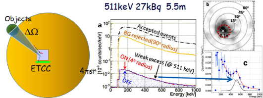
To overcome this problem, it is necessary to completely solve the kinematics of Compton scattering, which can be achieved by measuring the direction of the recoil electron. As shown in Fig. 1, the ETCC focuses MeV gamma rays emitted from the point source to one point, similar to optical telescopes. Only the determination of both the angles of incident gamma-rays surely enables selection of the gamma-rays in the FoV from background gamma-rays coming from the outside with the resolution of the PSF and to estimate the leakage of the background from the outside of the FoV, as shown in Fig. 5 (Tanimori et al., 2017, 2015). Additionally, such a proper PSF gives us the ON region, as well as the interested region and OFF-regions, which are hardly affected by the ON region in the same FoV.
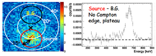
The background-subtracted signal is obtained using the ON-OFF method, as shown in Fig. 6 (Tanimori et al., 2015). Thus, the precise definitions of the FoV and background regions make it possible to quantitatively evaluate the detection of the signal. These methods and concepts are essential and common in all fields of astronomy and science using imaging analysis. Furthermore, the intensity independence of each point above the PSF in the image ensures that the spectrum of each point comes from that location, as shown schematically in Fig. 5, which is called imaging spectroscopy (Tanimori et al., 2015). As explained previously, most universal imaging analysis methods are based on a clear definition of the PSF, and a sharper PSF provides better quantities from imaging analyses in general.
4.2 Background rejection in ETCC
Another serious problem is the large radiation background in space. Although gamma backgrounds coming outside the FoV are significantly reduced by the linear imaging system, other types of backgrounds, such as neutrons, missing charged cosmic rays, accidental events, and misreconstructed events, are difficult to remove completely via this method. In the reconstruction method in particle physics, additional physical parameters that are not used to solve the kinematics are usually needed to suppress such a background. In MeV gamma-ray telescopes using the reconstruction of Compton scattering, residual physical parameters are considered necessary (Tanimori et al., 2017). We have good examples. COMPTEL successfully opened MeV gamma-ray astronomy by detecting approximately 30 celestial objects using a CC (Schoenfelder et al., 1993; Schoenfelder, 2000), although the actual sensitivity was degraded by 25% compared with that expected before launching (Schönfelder, 2004). According to the experience of SMILE-2+, this success is mainly attributed not to the imaging of the CC method but to the efficient background rejection based on the time of flight (ToF), the pulse analysis of the forward liquid scintillator, the reduction of the FoV (limited to 30), and the adoption of a light material as a scatterer of the forward detector (FD). In principle, the CC cannot distinguish correctly reconstructed Compton scattering events (signal) from misreconstructed background events, owing to the incompleteness of the event reconstruction. COMPTEL adopted several tools to reduce the background; in particular, the ToF was effective for removing most of the background coming from the downward direction, which accounted for approximately 90% of the total background (Schönfelder, 2004). Additionally, the pulse-shape analysis provided a good reduction of the neutron background, and the adoption of a light material was effective for reducing the accidental background to reduce the single hit counts in the FD. The narrow FoV was effective for reducing the large background coming from outside the FoV, although it also reduced the detection area. COMPTEL appears to be able to reduce the background by more than one order of magnitude and thus detect the celestial objects. However, there remains a large background exceeding that of cosmic diffuse MeV gamma rays by approximately one order of magnitude, as shown in Fig. 2 of (Kappadath et al., 1996). Thus, the study of COMPTEL indicates that additional parameters, except for those needed to solve the kinematics of Compton scattering, must be employed in MeV gamma-ray telescopes.
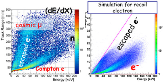
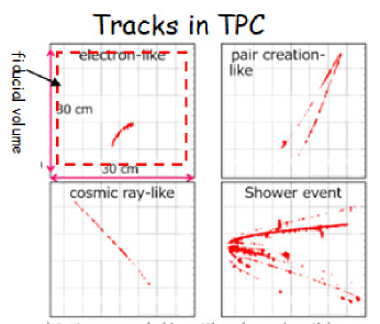
The measurement of the track of the recoil electron provides additional parameters such as the energy loss rate (E/x) of the particle track (Figs. 7 and 19), the scattering angle between the recoil electron and the scattered gamma rays in Compton scattering (Figs. 1 and 4), and the event topology, as shown in Fig. 8 (Tanimori et al., 2017, 2015). The correlation between E/x and the energy of the tracks is useful for particle identification, enabling to distinguish recoil electrons from cosmic rays, high-energy electrons, and neutrons. The angle can be determined using the kinetic form of the kinematic equation and from the measurements of the directions of the recoil electrons and scattered gamma-rays. Then, the two angles can be compared to determine whether the gamma direction calculated via the kinematical equation is correct or false, which is referred to as the kinematic test. Furthermore, an event topology enables easy determination of whether the measured event is due to Compton events caused by gamma rays by requiring only one fully contained track in the tracking instrument, as shown in Fig. 8.
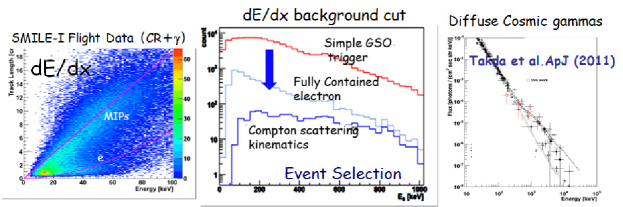
From the results of the ground experiments (Fig. 9) and two balloon experiments, E/x and the event topology were confirmed to be more efficient than the ToF in COMPTEL without the loss of the true signal events (Takada et al., 2011). The combination of the two reduced the background by more than two orders of magnitude at an altitude of 35 km to maintain a wide FoV of 3 sr.
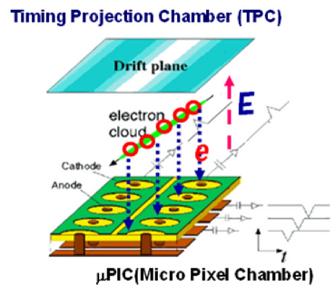
To realize the aforementioned requirements for almost all recoil electrons ranging from a few kiloelectronvolts (keV) to several MeV, an ideal three-dimensional (3D) tracking device such as a cloud chamber that provides a fine image of beta-decay electrons is necessary. A gaseous TPC enables the measurement of the 3D image of such a fine track of the above energy region electrically by using a micropattern gas detector (MPGD), as shown in Fig. 10 (Tanimori et al., 2004), where the 3D position of the track can be measured with a sub-mm pitch. Herein, such a TPC is referred to as a TPC. Because a 10-keV electron track runs along 5 mm in 1 atm Ar gas, 10 points in one track can be measured, whose pitch is similar to the diffusion of the drift electron passing through a distance of a few tens of centimeters in the TPC.
4.3 Estimation of sensitivity of ETCC in MeV gamma astronomy
For celestial objects, the sensitivity of telescopes is generally calculated by knowing the effective area, proper PSF, and background flux (Tanimori et al., 2015). The background comprises the flux of cosmic diffuse gamma-rays (CDG), which has a celestial origin and is the minimum background that is never removed; albedo gamma rays from the atmosphere; and instrumental radiation generated by cosmic rays. First, let us consider the minimum effective area and worst PSF to reach a sensitivity of 1 mCrab during the observation time of 106 s for the ideal case in which all background except CDG could be removed. For a PSF of a few degrees, a relatively small effective area of a few 100 cm2 is needed because the typical fluxes of celestial gamma rays in the MeV region are three orders of magnitude stronger than those in the GeV region. If the PSF was <10, an effective area 100 times larger would be necessary. Considering the limitations of the size and weight of middle-class satellites, a possible scale of the effective area for the MeV gamma telescopes is estimated to be a few to several hundred cm2 for 1-MeV gamma-rays at maximum. Thus, a proper PSF of a few degrees and complete background rejection should be achieved simultaneously for all MeV gamma sky surveys, aiming for a sensitivity of <1 mCrab (Tanimori et al., 2015).
Almost all proposals for MeV gamma astronomy using CCs mention the effective area and the ARM (Angular Resolution Measure) as an angular resolution or the effective PSF; however, they hardly describe the method of estimating the sensitivity from the effective area and ARM quantitatively. As mentioned previously, the image of the CC is a nonlinear system. In a linear system, the event density of the imaging plane increases linearly as the number of photons entering the FoV increases, whereas the event density increases almost with the square of the number of photons because each event annulus surely crosses several other events whose number increases linearly as the events increase, as shown in Fig. 5. The following general formula for estimating the sensitivity in astronomy must not be used simply for the CC. In astronomy, the significance of a source is
| (2) |
which can be approximated in the background-dominated case to
| (3) |
where is the signal intensity, the background flux, is the effective area, and is the half-power radius of the PSF.
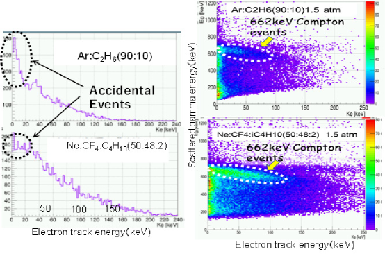
A gaseous tracking device for measuring the recoil electron direction is a unique solution. How can a gaseous detector provide the required effective area in a 1-m3 cubic volume? The key point of Compton scattering is that it is proportional to the atomic number or electron density, in contrast to the photoelectric effect. Molecular carbonic gas is a good choice for the scatterer. CF4 has 42 electrons in one molecule, which is nearly three times that of Si, and its low atomic number significantly suppresses the photo absorption of gamma rays in the scatterer, which is the main reason for the accidental background (Tanimori et al., 2017, 2015). Fig. 11 shows the good enhancement of the Compton events and suppression of the accidental events due to the use of CF4 gas measured by a (10 cm)3 cubic ETCC in 2015.
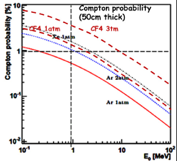
COMPTEL uses a liquid scintillator as the scatterer, which comprises mainly carbon and hydrogen (Schönfelder, 2004). A (50 cm)3 cubic CF4 gas with 3 atm gives an effective area of 110 cm2 for 1-MeV gamma-rays, as estimated from Fig. 12, and a tracking device with a 50-cm2 effective area is easily realized using TPC technology. The TPC can measure the 3D position of a charged particle inside a large gas volume using only one 2D MPGD. A (50 cm)3 cubic TPC is relatively small and obtains a position resolution of a few hundred micrometers without the magnetic field to suppress the diffusion of the drift electron in the gas volume. If 40% of the Compton scattering is detected in the TPC, 4 (50 cm)3 cubic TPCs provide an effective area of 200 cm2 at 1 MeV. Sub-mm sampling with a size of 50 50 cm2 is common for MPGD, and the gas amplification of 104 in the TPC enables the use of simple, light, and low-power readout electronics. Thus, the gaseous TPC reduces the amount of readout electronics by more than one order of magnitude compared with the multi-layer solid detector. Furthermore, there is no material except the gas in the TPC gas volume; thus, scatters that took place in the scatterer can be selected by measuring the electron track inside the gas volume. A multilayer structure requires many materials to be supported. cooling, and electrically handling the scatterer devices inside and near the FD of the CC, which causes a huge background that is not distinguished from real events scattered in the scatterer.
Additionally, the TPC provides a moderate energy resolution for the electron track at room temperature: 20%, 10%, and a few % for 10, 50, and 100 keV, respectively. By combining a good scintillator or a heavy semiconductor as the absorber surrounding the TPC, a good energy resolution of 2%–5% at 662 keV was obtained at room temperature.
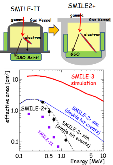
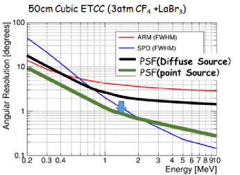
For the use of gas as a scatterer, there is one serious problem: a recoil electron with an energy higher than several hundreds of keV penetrates the TPC and significantly reduces the effective area for gamma-rays above a few MeV. To overcome this problem, all absorbers were moved inside the TPC in the SMILE-2+ experiment (Mizumura et al., 2017; Takada et al., 2022), as shown in Fig. 13. Recoil electrons with energies of 1 MeV provide a good sub-degree SPD (Scatter Plane Deviation) for gamma rays above a few MeV, as shown in Fig. 14, while the ARM is saturated to a few degrees above a few MeV (Mizumura et al., 2017).
4.4 How to obtain a good PSF
The PSF is the most significant factor for attaining a good sensitivity. In Compton scattering, the PSF is determined equivalently by the two angular resolutions of the elevation and azimuth in general, as shown in Figs. 14 and 15. The former is the ARM, and the other is a function of the SPD (Tanimori et al., 2017, 2015). To obtain a good PSF, the two angular resolutions must be similar. The ARM depends on the energy resolution of the telescope, and as the Compton scattering angle increases, the ARM becomes worse. Although the theoretical ARM of the forward scattering region is better (by a few degrees) than those in larger scattering regions, the ARM is degraded by geometrical errors owing to the position resolutions of the scatterer and absorbers and systematic errors of the instrument structure. Because the position resolutions of semiconductors or gaseous TPCs are sub-mm, the real ARM depends on the distance between the hit points of the scatterers and absorbers, which is the instrument size.
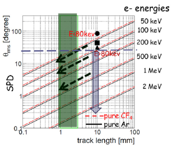
For COSI with Ge (Kierans et al., 2020) and SDGs (Soft Gamma Ray Detector) on Hitomi satellite with cooling Si and CdTe (Watanabe et al., 2014), an ARM of 6 at 511 and 662 keV were reported, respectively, with energy resolutions of <1% and 2 % at 662 keV, but for the (30 cm)3 cubic ETCC of SMILE-II, an ARM of 5–6 at 662 keV was obtained using a GSO scintillator with an energy resolution of 11%. A TPC with a Gd3(Ga,Al)5O12(Ce) (GAGG) scintillator having a good energy resolution of 5% at 662 keV provides a good ARM of 4 at 662 keV (Tanimori et al., 2017, 2015). However, for a good PSF, the improvement of the SPD is far more important considering the present resolution. Because the SPD is the angular uncertainty of the Compton scattering annulus, it improves the resolution of the PSF by roughly a factor of the ratio of the scattering angle to 180 (Tanimori et al., 2017; Mizumura et al., 2017). For example, an SDP of 25 (full width at half maximum, FWHM) with an ARM of 5 (FWHM) gives a 3 HPR (Half power radius) as the PSF, which is similar to the PSF of EGRET at 100 MeV (Goddard Space Flight Center, 2021), as shown in Fig. 15. The SPD is mainly determined by the multiple scattering of recoil electrons in the scatterer. As shown in Fig. 16, a good PSF requires an SPD smaller than 20, which is obtained by a few 100 3D sampling of a gaseous TPC.
This requirement was already attained by the MPGD TPC used in the SMILE project. For Si, 100-nm 3D sampling is required, which is difficult, even in the near future. Thus, only gaseous TPC has the ability to provide both a sufficient PSF and an effective area to attain sub-mCrab sensitivity in a satellite-scale detector, which is an essential reason for using a gas detector for MeV gamma-ray imaging spectroscopy (Tanimori et al., 2017; Mizumura et al., 2017).
4.5 Development of ETCC
The ETCC is a unique instrument that satisfies all the aforementioned requirements for a breakthrough in MeV gamma-ray astronomy. As shown in Fig. 1, the ETCC consists of an FD as a scatterer of gamma-rays and a backward detector (BD), which functions as a calorimeter for the scattered gamma-rays. A gaseous TPC is used as the FD, which is based on MPGDs, to measure the 3D tracks of recoil electrons, and pixel scintillator arrays (PSAs) with heavy crystals (at present, Gd2SiO5:Ce, GSO) are used for the BD. Ar-based gas was used for TPCs with an energy resolution of 30% at 5.9 keV because the gas amplification of CF4 gas requires a higher voltage than that of Ar gas (Tanimori et al., 2017). Although a micropixel gas counter (PIC) (Ochi et al., 2000) was originally developed to provide a higher gas gain of in MPGDs, which are mostly operated with a gain of <104, the PIC was operated at a lower gain of to avoid discharge damage. Additional gain was provided by a GEM with a gain of several units, and a total gain of – obtained routinely. This two-step gain system has provided stable operation for more than 10 years. Recently, a new PIC was developed using a glass substrate instead of a polyimide one (Abe et al., 2020) and this new PIC is not destroyed by discharges and provides a higher gain than the present PIC by a factor of 2. Operations with CF4 is planned, so as to attain an effective area of 10 cm2 for a (30 cm)3 cubic TPC.
The energy resolution of the ETCC with GSO scintillators using a photomultiplier tube was 11% (FWHM) at 662 keV. New PSAs with GSO + SiPM and GAGG + SiPM can yield 8% and 5% (FWHM) at 662 keV, respectively.
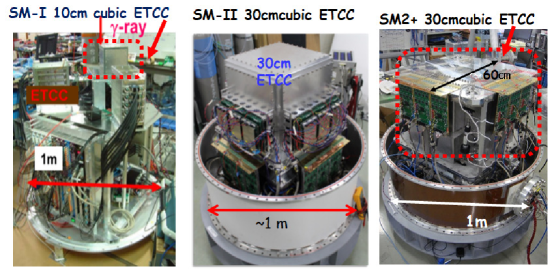
In 2004, for the first time the successful full electron tracking in a laboratory experiment with a small (10 cm)3 cubic ETCC was reported (Tanimori et al., 2004; Takada et al., 2005). Then the “Sub-MeV gamma ray Imaging Loaded-on-balloon Experiment” (SMILE) project was conducted with the improved (10 cm)3 cubic ETCC (SMILE-I in Fig. 17) to measure the diffuse cosmic MeV gamma-rays via a balloon-borne experiment in 2006 (Takada et al., 2011). An excellent particle-identification ability according to the E/x of an electron track in the gas was demonstrated as shown in Fig. 18, from which the background level was reduced by a factor of 3.
A (30 cm)3 cubic ETCC (Figs. 1 and 17) was then developed to achieve an effective area of 1 cm2 at 300 keV (Fig. 13) for the detection of celestial MeV-gamma-ray objects such as the Crab with a balloon experiment in the Northern Hemisphere (SMILE-II) (Tanimori et al., 2015). In this ETCC, the tracking efficiency in the TPC is improved significantly (from 10% to 100%) compared to SMILE-I owing to the improved readout electronics and algorithm. This provides better noise reduction of E/x and good angular resolutions of 5.9 (FWHM) at 662 keV, which is consistent with that calculated using the detector energy resolution (Mizumoto et al., 2015).
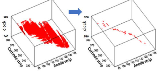
For the ETCC, obtaining the direction of the recoil electron is crucial. In the PIC of the TPC, orthogonal strips of the X and Y coordinates were used to significantly reduce the number of readout channels from the pixel readout. However, this readout method causes a well-known left–right uncertainty in tracking multiple hits simultaneously as shown in Fig. 19 (Tanimori et al., 2015), which degrades the SPD considerably to 200 (FWHM) with SMILE-I. In the new readout electronics of SMILE-II, the pulse width of each electrode in the PIC is recorded as the timing width over the threshold (TOT) (Mizumoto et al., 2015), which provides a coarse charge deposit at each hit point. In 2015, using the TOT, the coincidence width between the X and Y strips could be reduced from 10 to 1 ns and the SPD improved to 100 (FWHM), thus reducing the uncertainty in tracking (Tanimori et al., 2015).
Consequently, a half-power radius of 25 for the PSF at 662 keV was obtained (Tanimori et al., 2015).
4.6 SMILE-2+ balloon experiment
SMILE-2+ was improved from SMILE-II for a sufficient sensitivity estimated according to the PSF for the Galactic Center (GC) diffuse gamma-ray flux (Tanimori, 2020; Takada et al., 2022). SMILE-II was the first (30 cm)3 cubic ETCC with 1-atm Ar gas, and PSAs were set outside the gas vessel of the TPC. SMILE-II was designed to use the ARM as a PSF for detecting Crab with 3 via several hours of observation in the Northern Hemisphere (Tanimori et al., 2015). However, given the importance of the proper PSF for the estimation of sensitivity (Tanimori et al., 2017), SMILE-II was redesigned to SMILE-2+ to realize the same sensitivity as that expected for SMILE-II, taking into account that the flux of Crab is reduced by half owing to the smaller zenith angle of 45 in the southern-sky observation (Takada et al., 2022). The effective area of SMILE-2+ was increased three times at 511 keV and several times above 1 MeV with Ar gas at 2 atm and the use of a GSO of double thickness in the bottom pixel scintillation arrays (PSAs). Additionally, because a fully contained electron in the TPC restricts the energy range of gamma-rays to <1 MeV, all the PSAs were set inside the TPC to detect the higher-energy recoil electron, as shown in Fig. 13.
A one-day observation was conducted with a large FoV (3 sr) for the entire southern sky during the JAXA balloon launching at Alice Springs of Australia on April 7–8, 2018 (Takada et al., 2022). The balloon was successfully flown at an altitude of 37–39 km for 30 h, and the southern sky was observed, including the GC, half of the Galactic disk, Crab, Cen-A, and the Sun.
4.7 Analysis for background reduction
triggered events were recorded and finally reduced to 105 events (by more than two orders of magnitude) with the requests of the fully contained and good for the recoil electron in the TPC. Here, the clear event topology enabled the efficient identification of Compton scattering. The number of final events is consistent with that estimated from the SMILE-I results, indicating a signal-to-background ratio of 1. This is clearly confirmed by the obvious enhancements of the detected gamma flux at 10% during the passage of the GC through the FoV, for both low- and high-energy events, as reported in (Takada et al., 2022). The ratio is consistent with previously reported data, and as a result, the final data contained only a few 10% of the instrumental background. Until now, for all observations of MeV gamma-rays done before SMILE-2+, the background was approximately 1–2 orders of magnitude higher than the signal. For SMILE-2+, because 3/5 of the whole sky was observed via bijection imaging, the OFF-region could be set simply with both the GC and the disk outside the FoV, and the significance showed enhancements of the GC and disk were observed.
ETCC has been demonstrated to enable MeV gamma-ray astronomy in the same manner as for astronomy at other wavelengths, i.e., bijection imaging and complete background rejection.
4.8 Future prospects
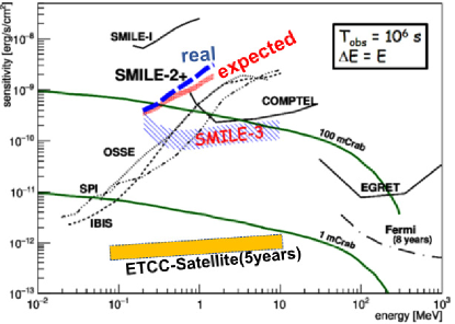
The next step will be the construction of SMILE3, a 40 cm 30 cm cylindrical ETCC with 3-atm CF4 gas and a 3-coordinate PIC, which give a 10-cm2 effective area and a good PSF of 5 (Takada et al., 2020, 2022). Thanks to the excellent rejection of background events, this detector will enable the study of the MeV gamma sky with a sensitivity several times higher than that of COMPTEL for only one-month-long balloon observation, as shown in Fig. 20.
Such a detector on a space mission would yield a sensitivity enabling the detection of faint sources at the sub-mCrab level, as shown in Fig. 20 (Tanimori et al., 2015). A few hundred cm2 and a PSF of a few degrees are required. Such a fine PSF requires a good SPD of 10, which is only possible when gas is used as a scatterer. With molecular gases, the needed effective area can be obtained from a 1-m3 sensitive volume. A proposal of such an ETCC on a satellite mission was submitted to the 2020 NASA Decadal Survey (Hamaguchi et al., 2019).
5 TPCs as pair telescopes
After the first exploration of the gamma-ray sky by COS-B and EGRET, it was recognized that further improvement in the crowded and/or bright part of the sky, such as the galactic plane, and further improvement at low energies would imply the removal of the high- converters and the use of low-multiple-scattering active targets, such as those consisting of gas drift chambers (Mukherjee et al., 1996). Later, and for similar reasons, the potential of such telescopes for the gamma-ray polarimetry, the measurement of the fraction and direction of the linear polarization of the incoming radiation, was underlined (Bloser et al., 2004).
5.1 Polarimetry with pair conversions and multiple scattering
Due to the nature of the photon, the reduced differential cross section of the interaction of photons with a charged particle, as a function of the azimuthal angle, , that measures the orientation of the final state in the plane orthogonal to the photon direction of flight, has the form:
| (4) |
-
•
is the fraction of the linear polarization of the photon beam;
-
•
is the polarization asymmetry of the conversion process; its value depends on the conversion process (pair, Compton, photo-electric) and on the photon energy.
A number of experimental effects affect the measurement of the azimuthal angle, among which multiple scattering is certainly the fiercest and has been one of the major obstacles to polarimetry with the past and present pair-conversion gamma-ray telescopes. The presence of a non-zero resolution on the azimuthal angle changes eq. (4) to
| (5) |
so the effective polarization asymmetry is afflicted with a dilution factor . The classical calculation (Kel’ner et al., 1975; Kotov, 1989; Mattox et al., 1990) of is performed assuming the small-polar-angle approximation, the most probable value of the pair opening angle , with (Olsen, 1963), and an approximate expression for the R.M.S. multiple scattering deflection (eq. (34.16) of (Zyla et al., 2020)), (, the track momentum, and are the material thickness traversed by the electron and the radiation length). Assuming an equal energy share, , we obtain (eq. (15) of (Bernard, 2013a)) with . A dilution of would be reached after a propagation of in silicon, for example, that is before the leptons could even exit the conversion wafer in a silicon-strip detector (SSD) active target.
The catastrophic exponential dependence of the dilution as a function of thickness so obtained, is not confirmed by the results of full simulations, actually, (Fig. 7 of (Bernard, 2019b), Fig. 3 of (Eingorn et al., 2018)). At high thicknesses, the dilution is found to be much larger (i.e. less degraded) for the full simulation, something which is the consequence of the distribution having a huge tail at large values (Olsen, 1963).
An optimal fit (such as a Kalman filter (Fruhwirth, 1987)) can be performed that takes into account multiple scattering and the space resolution of each of the detector layers . For homogeneous detectors, the single-track angular resolution at the vertex is found to be , with , being the longitudinal sampling (along the track). Given the scaling of the distribution (Olsen, 1963), the induced dilution is then found to be higher (less degraded) at low energies (Fig. 20 of (Bernard, 2013a)).
5.2 Past experimental achievements and future prospects
Gamma-ray beams are currently produced in the laboratory using the Compton scattering of a laser beam on a high-energy mono-energetic electron beam. Gamma-ray pseudo-monochromaticity is achieved by selecting the “Compton-edge” with a cylindrical collimator on the forward axis. The linear polarization of the incident laser beam is then transferred almost exactly to the gamma-ray beam (Sun and Wu, 2011).
5.3 HARPO
The HARPO project (Hermetic ARgon POlarimeter) has developed a gas TPC prototype (Bernard, 2019a) and characterized it on the gamma-ray beam of the BL01 beam line at LASTI (Gros et al., 2018), with a gamma-ray energy that could be tuned from 1.7 to 74 MeV.
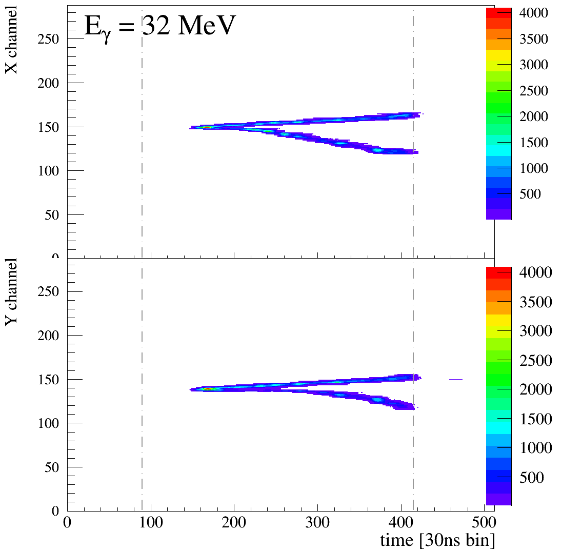
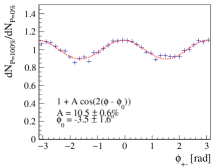
The drift volume was cubic, , filled with a (95-5 %) argon-isobutane gas mixture at a pressure that was varied from one to four bar. Most of the data were taken at , for which a uniform electric field provided an electron drift velocity of . The signal was amplified by a then novel GEMmicromegas combination, the performance of which was characterized carefully (Gros, 2014). The anode was segmented to two series of orthogonal strips () at a pitch of , and the signal sampled at a pace of , equivalent to given the value of the drift velocity. The prototype was routinely exposed to beam for five weeks, with an incoming single-track background rate of several kHz, that is larger than that expected on a space mission, a background that created negligible pile-up and no visible gas degradation in a sealed configuration. An excellent value of the polarization-asymmetry dilution was observed (Fig. 21 and (Gros et al., 2018)).
5.4 AdEPT
The Advanced Energetic Pair Telescope (AdEPT) is currently being developed at NASA/GSFC. The primary science goal of AdEPT is to study the polarization of photons with energies above 1 MeV, interacting via pair production (Hunter et al., 2014). The polarization angle of the photon is observable as the azimuthal angle of the electron-positron pair. To preserve the azimuthal angle of the pair, and subsequently measure it, requires that Coulomb scattering of the pair in the interaction medium be minimized. Thus, the density of the medium must be low.
A low interaction medium density is easily achieved with a gaseous TPC detector (). However, the gaseous medium has a corresponding large radiation length (). Maximizing the interaction probability () requires increasing the overall instrument interaction depth to compensate for the low interaction medium density. However, the maximum interaction depth is limited by the maximum allowable diffusion of the ionization electrons as they drift through the TPC. The diffusion of the ionization electrons obscures the tracks and consequently reconstruction of the azimuth angle of the electron-positron pair. A useful limit to the maximum TPC drift distance is that distance which results in an electron diffusion equal to twice the pitch of the readout plane (Arogancia et al., 2009). Increasing the total detector depth beyond this limit requires adding additional readout planes or reducing the diffusion of the drifting ionization charge.
The NI technique, discussed above, is an effective approach to reducing the diffusion in a TPC. The introduction of an electronegative component into any TPC gas mixture effects the operation of the TPC in three ways. One, the diffusion of the ionization charge is reduced to the thermal limit, two, the drift velocity of the ions, which depends on the major component of the gas, is reduced by 3-4 orders of magnitude compared to the drift velocity of free electrons in the gas, and three, the effective gas gain of the readout plane is reduced. This reduction in gas gain, corresponding to a reduction of the path over which the Townsend avalanche develops, is due to the initial acceleration of the NI process leading to knocking the ionization electron free from the NI and allow the avalanche to occur. To take advantage of the reduced diffusion in a NI-TPC, the effects of the reduced drift velocity and increased gain must be accounted for in the TPC design.
Design of a NI-TPC Pair Telescope
The NI diffusion is reduced to the thermal limit, independent of the TPC gas mixture (Dion et al., 2011), however, the NI drift velocity depends on the molecular mass of the TPC gas. The velocity in low mass gases, e.g. argon, is faster compared with heavier gases, e.g. xenon. The NI drift velocity, in argon is 20 m/s, corresponding to a total drift time of 50 ms/m of drift. This slow drift velocity allows the spatial resolution of the TPC readout to be very high while at the same time reducing the speed (bandpass) and power of the readout electronics.
Reduction in the diffusion from the free electron diffusion rate, Eq. (1), to the thermal limit is dramatic. For example, at , the electron diffusion in a mixture of argon and CO2 is reduced from 300 (Piuz, 1983) to 80 at 300K. This reduction allows the drift distance, or detector interaction depth, corresponding to a given amount of diffusion, to be increased by a factor of 16, thereby dramatically increasing the interaction probability of the instrument without additional layers of readout electronics.
The slow drift velocity of the electron-positron tracks in a NI-TPC does not absolutely rule out the use of a calorimeter. If the electron and positron from an interacting photon cross the readout plane and enter a calorimeter directly underneath the readout plane, their energies from a position sensitive calorimeter could be correlated in time with the TPC signals of the electron-positron crossing the readout plane. Requiring this pair event geometry, however, severely reduces the effective area of the telescope and eliminates the nearly isotropic ( steradian) sensitivity achievable with a TPC based gamma-ray telescope operating in low Earth orbit.
The slow drift velocity does, however, introduce timing coincidence problems for a gamma ray telescope if a design similar to previous gamma-ray telescopes (e.g. EGRET, Fermi-LAT) is following. All previous imaging telescope designs have consisted of a multi-layered tracker system mounted above a calorimeter and the tracker surrounded by an anti-coincidence system (ACS).
Using a NI-TPC as the interaction medium and electron-positron pair tracker for a pair telescope and realizing the elimination of the ACS and calorimeter subsystems from the telescope design requires instrument solutions to overcome the slow drift velocity of the NIs. The advantages of eliminating the ACS and calorimeter subsystems are two-fold.
First, eliminating these two massive and complex detector subsystems reduces telescope complexity, mass and hardware cost. Second, the geometric size of the telescope, and hence its sensitivity, is determined by the dimensions of the launch vehicle payload shroud rather than total telescope mass.
We discuss the AdEPT instrument solutions being developed to these concerns below.
Elimination of the ACS
Previous telescope designs utilized an ACS to veto the instrument triggering circuit for a few after a cosmic ray traverses the detector volume. The slow drift velocity of a NI-TPC would require the veto signal to last tens of milliseconds in order for the ionization charge left by a cosmic ray traversing the volume to completely drift through the volume. In a 550-600 km circular low Earth orbit, the cosmic ray proton flux is protons/s/m2 (SPENVIS, 2021). This proton flux and the long veto signal period would result in the TPC readout being gated off 100% of the time. Thus, we conclude that the ACS is ineffective and can be eliminated from the design of a gamma-ray telescope using a NI TPC. Since the ionization charge produced by the cosmic-rays cannot be discriminated, the problem becomes how to locate the interacting gamma-rays in the background of cosmic ray tracks.
Modern computer hardware, particularly graphics processing units (GPU) and field programmable gate arrays (FPGA) have evolved to the point where artificial intelligence/machine learning techniques can be used to search the NI TPC data for the electron-positron pair vertex signature of interacting gamma rays. The raw data is read out continuously and segmented into overlapping time intervals of about 50 ms duration. Each interval is then searched for the inverted “” signature of a pair interaction. Those intervals containing an interaction are discriminated from the large number of background tracks from cosmic ray and low-energy photon interactions (Garnett et al., 2021). These background events are eliminated from the raw data and only those intervals containing pair interactions form the instrument science data.
Eliminating the Calorimeter
As discussed in Section 3, the energy loss of a charged particle traversing a medium is described by the Bethe formula, see eq. (33.5) of (Zyla et al., 2020). The mean energy loss of electrons is tabulated as a function of energy in ESTAR (Berger et al., 2010a).
The mean energy loss is then compared to the calculated average energy loss (Berger et al., 2005) to determine the energy of the original electron (Allison et al., 1974, 1976; Allison and Cobb, 1980; Cobb et al., 1976). The positron energy loss and electron energy loss differ by a few percent (Rohrlich and Carlson, 1954). This difference, however, is too small to be used to differentiate the pair electron from the positron.
For charged particles traversing a gaseous TPC, the actual energy loss, in terms of ion pairs per cm, is Poisson distributed about the mean and fluctuates widely. Thus, any single sample of the dE/dx is a poor indication of the particle energy. The high granularity (sampling rate) of a TPC provides a large number of samples of the dE/dx loss in the gas. The mean energy loss can be determined from these samples and the actual energy of the electron and positron can be estimated.
The energy loss as a function of particle energy is double valued about its minimum ionization value. Thus, any mean energy loss corresponds to two possible particle energies, one above the minimum ionizing energy and one below. The lower value can be confirmed or discarded based on the total range of the particle range. A particle with dE/dx below (dE/dx)min will have more pronounced Coulomb scattering or will stop in the gas.
AdEPT Instrument Design
The AdEPT instrument takes advantage of the NI-TPC technique to provide a low density interaction medium and to optimize the sensitivity for pair polarization. The gas mixture, 90%/10% argon/methane plus 40 torr of CS2, was chosen to provide, 20 m/s, drift velocity. A total pressure of 1.5 atm was chosen to provide significant pair interaction depth, while minimizing the Coulomb scattering of the electron-positron, and allows for a thin (3 mm aluminum) pressure vessel (Hunter, 2018).
The AdEPT instrument is composed of two gaseous NI-TPCs stacked so their drift electrode is common to the two TPCs and the two readout planes are at the top and bottom of the stack (Hunter, 2018). Each TPCs has large, 4 m2, geometric area and 1 m depth and two-dimension readout plane based on the micro-well detector (MWD) (Deines-Jones et al., 2002). This configuration of the TPCs allows the largest physical separation between the common high voltage drift electrode and the lower voltage readout planes, spacecraft structures and pressure vessel, which are at ground potential.
The two-dimension MWD readout plane has electrodes in both the X- and Y-dimensions on pitch. The readout sampling frequency, 20 m/s / 400 = 50 kHz, is chosen so that the vertical coordinate digitization is also 400 . This results in a very high granularity of 25 samples per cm of track for the AdEPT NI TPC and only 4 cm segment of the electron or positron track provides 100 samples of the dE/dx energy loss of the particle.
Micro-Well Detector Readout Plane
The MWD readout plane is fabricated using flex printed circuit board techniques. The currently available flex circuit technology allows for fabrication of multi-layer circuits with line and gap separations as small as 75 on areas up to about 50 50 cm2. This allows for large area TPC readouts to be implemented by tiling detector smaller pieces together. The only limitation to the readout dimension and area is the capacitance of the electrodes.
The micro-well detector is fabricated as a two layer flex circuit with subsequent laser ablation to form the micro-wells (Deines-Jones et al., 2002). The cathode electrode strips, about 200 wide on 400 pitch, are on the top surface of the flex circuit and the orthogonal anode electrode strips, similarly about 200 wide on 400 pitch, are on the lower layer. The cathode electrodes are perforated with 150 diameter openings aligned with the crossings of the underlying anode electrodes. A subsequent operation, using excimer laser ablation, is used to open the 100 diameter micro-wells in the center of each hole in the cathode electrode. The thickness of the insulating layer determines the depth of the wells and the maximum gas gain (Deines-Jones et al., 2002).
This MWD geometry was considered to be a promising detector technology since the avalanche occurs in the strong gradient of the electric field in the wells and the charge is collected onto the anodes. Motion of the positive ions resulting from the avalanche induce an equal but opposite signal on the cathodes. Fabrication of large area MWDs using laser ablation coupled with real-time optical alignment to insure that the wells were centered on the cathode openings was investigated over many years at GSFC ultimately producing detectors as large as 30 30 cm2. These detectors were operated with gas gain as high as (Son et al., 2010).
A wide range of laser and chemical etching techniques were explored with industrial vendors to transfer the MWD to industrial fabrication. However, we realized that the position of the micro-wells had to be concentric, within a few microns, of the circular openings in the cathode electrodes. This accuracy requirement rendered industrial fabrication impractical. Deviation of the well from being centered in the cathode holes, by more than a few , led to breakdown of the anode-cathode voltage which limited the gas gain performance. The high gain lifetime of these detectors was also decreased by reduced breakdown voltage. This effect, attributed to charge migration in the insulating layer caused by the very strong electric field in the wells, limited the lifetime of these detectors to only a few months of operation. These considerations led us to discontinue development of MWDs at GSFC.
The -PIC Detector Readout Plane
We are currently updating the design of the AdEPT instrument, retaining the NI TPC concept and size, but replacing the MWD readout with the Japanese -PIC+GEM detector developed for the ETCC discussed in Section 4 (Takada et al., 2011). A schematic diagram of the -PIC, without the GEM layer, is shown in Figure 10.
The electrode structure of the -PIC detector is similar to the MWD and is fabricated as a multi-layer flex circuit. The cathode electrodes, on the top surface, are separated from the anodes on an underlying layer with a polyimide insulating layer. The anode electrodes have posts (filled vias) extending up through the insulating layer, typically about 100 thick, and exposed in the center of vias in the cathodes. These exposed anode posts and surrounding cathode strips form the proportional detector structures. The anode-cathode gap is 100 and the Townsend avalanche forms in the gas above the cathode layer.
Readout Electrode Design
The front-end electronics of the readout plane, typically a charge sensitive amplifier on each electrode, can be implemented either with discrete electronics or as an ASIC. These implementations have an intrinsic minimum equivalent RMS noise value of about electrons. Thus, a reasonable minimum detector gain for a non-NI TPC is to provide a minimum three-to-one signal-to-noise ratio. Implementation of the NI technique reduces the effective gain of the readout because the NI must move deeper into the strong electric field until the ionization electron is knocked off of the NI at which point the free electron begins the avalanche process. This motion of the NI reduces the effective gain of the TPC readout by a factor of 200. The minimum gain of a NI TPC must be increased by this factor to retain the minimum signal-to-noise ratio. Thus, the required minimum TPC gain is which is higher than is achievable with a single micromegas amplification stage (Veenhof, 2010). The solution, for a NI TPC, is an additional gain stage in the form of a gas electron multiplier (GEM).
The anode and cathode signals of a TPC are negative and positive charge, respectively. Thus the charge amplifier must have bi-polar response or two different versions of the amplifier are needed for the anodes and cathodes. These amplifiers can be implemented using operational amplifiers and other discrete components or an application specific integrated circuits (ASIC) can be used. The discrete approach offers a means to quickly develop a modest number of channels when beginning detector development. This approach is not the lowest power solution, in most cases, but does allow for easy modification of parameters such as gain and shaping time.
The readout electrodes, which operate at high voltage, require a high voltage blocking capacitor to couple the charge signal to the amplifier inputs. These capacitors are large compared to the detector pitch and are a design problem for the electronics. An option, explored for AdEPT instrument is to float the amplifier grounds to the corresponding anode or cathode voltages thereby eliminating the need for high voltage blocking capacitors. This approach also requires that the grounds of all the subsequent analogue electronic stages be floated. This is done up to the digitizer stage where the serial output of which is easily level shifted and the remainder of the event selection and background discrimination is done at spacecraft ground.
ASIC Readout Electronics
The advantages of discrete electronics are quickly lost when the channel count exceeds a few hundred channels at which point selection of an integrated circuit becomes appealing. Over the past several years there have been many general purpose ASICs developed for large experiments at CERN and by industry, e.g. IDEAS (IDEAS, 2021).
The design of an ASIC unique to a specific detector is another option that offers the advantages of tailoring the electronics to the detector and incorporating specific features into the electronics. Such development requires several years of lead time, is expensive, and cannot typically be done until the detector performance is well defined.
An ASIC design investigated for AdEPT is a bi-directional switched capacitor charge integrating amplifier. The adjustable integration time, 20-15 , provided direct digitization of the TPC charge for each electrode with resolution. The advantage of integrating the charge in the front-end electronics is that the discrete charge density corresponding to a discrete TPC voxel (three-dimensional volume) is directly measured. This ASIC design was completed and the performance simulated, however, funding issues prevented fabrication of test ASICs.
AdEPT Performance
Expected performance of the AdEPT gamma-ray polarimeter based on a NI TPC in low Earth orbit is summarized below. The detailed calculations are given in (Hunter et al., 2014).
The effective area compared to the Fermi LAT front is only 20% at 100 MeV but increases rapidly at lower energies and is about five times higher than Fermi LAT at 20 MeV. The point spread function approaches the kinematic limit for pair production (the angular resolution due to the unmeasurable nuclear recoil) and is less than twice the kinetic limit (Bernard, 2013b) up to 150 MeV, where . This excellent angular resolution contributes to a continuum sensitivity of about 10 mCrab over the energy range from 5 to 200 MeV. The minimum sensitivity, , is reached at 70 MeV. The minimum detectable polarization (MDP) for a 10 mCrab source is 4% and for a brighter, 100 mCrab source, the MDP decreases to 0.7% at 15 MeV.
AdEPT Future Prospects
The next phase of the AdEPT mission development will assemble a prototype of the AdEPT TPC using the -PIC+GEM readout plane and existing discrete electronics. Testing of this prototype with radioactive sources will provide data with realistic level of backgrounds. This data will be used to develop the software solutions to discriminate the electron-positron pair interactions from the background and determine the electron-positron momenta. Additional software will determine the gamma-ray incident direction, energy and polarization angle from the pair momenta.
5.5 Liquid or Solid TPCs.
Given the volume limitation on a space mission and the weight of the pressure vessel needed for a gas detector, using a liquid detector seems to be tempting (Caliandro et al., 2013), with a density gain of a factor of 840 for Argon, with respect to gas. For polarimetry, the performance of the tracking system must scale accordingly, something which presents several difficulties. In particular, the typical collected electrical charge is left unchanged by the double scaling (same collected charge on a 1 cm track segment in gas as on a segment in a liquid): an issue arises from the fact that gas detectors allow charge amplification in the gas while liquid argon does not, so single-phase liquid-argon detectors do not allow such a small scale tracking.
Some amplification can be achieved, on Earth, by the use of a two-phase system in which the active target consists of liquid, from which the electrons are extracted for amplification in the gas. In zero gravity on orbit, the stability of the gas-liquid interface might be an issue, possibility solved by performing amplification in bubbles inside the holes of GEMs (Erdal et al., 2019). An other possibility to fix the dense-gas interface is to use a solid TPC, as the electron-transport properties of solid noble gases are similar to that of liquid noble gases (though with a somewhat larger drift velocity) (Aprile et al., 1985).
An other issue is diffusion, as the coefficient saturates in liquid argon for high electric field, at a value of . The diffusion of the electron cloud during drift cannot scale with density, and the two tracks merge to a common blurred single track close to the vertex. Polarimetry with conversions to pairs, with a dense (liquid or solid) TPC, seems to be out of reach.
The Compton Spectrometer and Imager (COSI) project is using a set of 1.5-centimeter thick Germanium slabs as a combined (active-target calorimeter) telescope, read with a two-fold series of strips; as the interaction depth in the detector is inferred from the charge collection time difference between the two sides (Kierans et al., 2020), COSI can rightfully be described as a Germanium TPC.
More on dense-phase TPCs and their possible use in gamma-ray astronomy is presented in section 6.
5.6 Effective area
In contrast to “thick” active targets, in which the conversion probability of the photon is close to unity and the effective area is the product of the geometric area by the efficiency, here for “thin” active targets, it is better expressed as the product of the detector sensitive mass, , by the attenuation coefficient, , which is found to be approximately proportional to (atomic number and mass, respectively) (Berger et al., 2010b). tends asymptotically, at high energy, to . The number of events is
| (6) |
mission duration; efficiency. For a “Crab-like” source with a spectral index of , with flux , with and perfect efficiency,
| (7) |
Values of for some materials commonly used in gamma-ray telescopes are listed in Table 1. The variation of as a function of is available in Fig. 2 of (Bernard, 2013a).
| Ne | Si | Ar | Ge | Xe | |||
| 10 | 14 | 18 | 32 | 54 | atomic number | ||
| 20.2 | 28.1 | 40.0 | 72.6 | 131. | mass number | ||
| 28.9 | 21.8 | 19.5 | 12.2 | 8.48 | specific radiation length | ||
| 17.0 | 23.5 | 27.0 | 45.3 | 67.1 | photon attenuation coefficient @ | ||
| 1.90 | 2.67 | 3.17 | 5.32 | 8.28 | |||
| 60 | 84 | 100 | 168 | 261 | number of (thousands) events per kg per year, | ||
| 9.8 | 9.7 | 9.3 | 9.4 | 8.8 |
For a argon-mission with full efficiency, acceptance, exposure and perfect dilution down to threshold, (), and , we would observe events with an average polarization asymmetry of and, therefore, a precision of the measurement of , for small , of . Note though, that the median energy above which half of the collected data would lie is as low as , which questions the ability to trigger / select / reconstruct / analyze low-energy conversions in the polarimeter.
In the more realistic case of a argon-mission with a threshold, above threshold and dilution, we would obtain events with , , and . Therefore the polarimetry of a cosmic source with pairs should focus on the brightest sources of the MeV sky, in the first place, and with a good-dilution, low-threshold, large-sensitive mass detector in orbit for several years.
5.7 Angular resolution
The primary interest of developing a telescope with an active target consisting in a gas TPC is the excellent angular resolution and, consequently, a sizeable sensitivity to the linear polarization of the incoming radiation. After a photon of momentum converted to a pair of leptons with momenta for the positron, for the electron and for the recoiling nucleus, with , we want to reconstruct the direction of the candidate photon from the measured values of and , as in general the track of the recoiling nucleus cannot be reconstructed. Therefore the single-photon angular resolution receives contributions from the following sources:
-
•
(1) the missing recoil momentum;
-
•
(2) the uncertainty in the magnitude of the momentum of each lepton.
-
•
(3) the uncertainty in the direction of the tracks;
(1) The kinematic limits for the recoil momentum are extremely large, for nuclear conversion from to , where is the nucleus mass, but in practice the high () part of the spectrum is strongly suppressed, both by the presence of a factor and of and terms in the differential cross section (the recoil direction is mainly transverse to the direction of the photon, and all the more so, asymptotically, at high energy). The induced contribution to angular resolution at 68 % containment is found to be (Bernard, 2013b, 2019b)
| (8) |
As the angular kick is not Gaussian distributed, 95 % and 99.7 %-containment values might be of interest too, see (Gros and Bernard, 2017; Bernard, 2019b).
(2) The contribution from the uncertainty in the magnitude of the momentum of each lepton varies like , as the fraction of the photon energy carried away by the positron, has a distribution that has a mild variation with energy, and as the distributions of the polar angles of the electron and of the positron, and , scale like . The relative track momentum precision, , depends on the device that is used for the measurement and is not detailed here. For , the induced contribution on the single-photon angular resolution is found to be negligible, compared to the two other contributions (Fig. 6 of (Bernard, 2013b)).
(3) Tracking, the determination of the direction of the tracks, faces the limited spatial resolution of the detector and the deleterious effect of multiple scattering. A tracking method that takes into account the two effects in an optimal way is the Kalman filter (Fruhwirth, 1987).
-
•
For continuous media, and for momenta for which multiple scattering is sizeable, and under the hypothesis that the detector is thin enough that momentum stays nearly constant throughout propagation, the precision of the measurement of the track angle at “origin” is (eq. (1) of (Bernard, 2019b))
(9) where is the longitudinal track sampling pitch, , normalized to the detector scattering length (Innes, 1993), is the precision of a measurement of the track position, and is the imaginary unit.
-
–
At low momenta (high ), only the two first measurements contribute significantly, and the angular precision is
(10) This takes place for . Above that value, the full power of the Kalman filter is at work, and the precision is
(11) -
–
At high momenta, such that multiple scattering can be neglected, track-fitting turns out to be a simple linear regression, and the angular resolution (for no magnetic field) is (Regler and Fruhwirth, 2008)
(12) This takes place for .
-
–
For a 4-bar, argon-based TPC (, ) with spatial resolution, longitudinal sampling, measurements along each track on average (), we obtain , , and : on most of the electron momentum range relevant for TPC-based gamma-ray telescopes, the single-track angular resolution is described by eq. (11), something which translates to a similar expression for the contribution to the single-photon angular resolution (Sec. 3.1.1 of (Bernard, 2013b)).
At , the kinematic contribution amounts to and the tracking contribution to (the two contributions are of similar magnitude for , ).
5.8 Sensitivity, gas choice
Any of the noble gases is appropriate as a base for TPC and MPGD design, from helium to xenon, with the exception of krypton, that is generally avoided for the radioactive decays of 85Kr would produce a permanent background noise in the detector, at a level of Bq per kg of natural Kr.
It could be tempting to use a high- gas, as the photon attenuation coefficient, and therefore the effective area per unit mass, is proportional to , but the radiation length decreases, so increases, and so the single-photon angular resolution, , degrades. The sensitivity to faint sources, , defined as the source flux at significance limit, is proportional to (eq. (8) of (Bernard, 2013b)).
-
•
Below , with the angular resolution at the kinematic limit, , presenting an interest for high .
-
•
Above , with , and , the sensitivity becomes , presenting a mild preference for low .
For polarimetry, an analysis that is so badly demanding for high statistics, one would favor high too, but the dilution degrades for higher values of (Fig. 20 of (Bernard, 2013a)). At low pressures (several bar), statistics is the dominant factor and high is preferred, while for densities tending towards that of the liquid (hundreds of bar) it is the opposite (Fig. 22 of (Bernard, 2013a)).
6 Dense phase TPCs
The use of noble gases in a dense phase, that is, liquid or solid, is similar to that in the gas phase, but a number of differences must be mentioned:
-
•
Most often pure noble gases are used, i.e., without a quencher111Note though that saturation value of the electron drift velocity in liquid noble gases can be enlarged by the addition of in concentration of various alkanes (Yoshino et al., 1976)., so diffusion could be an issue; these pure materials are transparent to their own scintillation light, so the scintillation signal can be used to generate a trigger, and / or to measure the energy deposited in the material.
-
•
Upon ionization of the material, a large electric charge is generated in a small volume (electrons and positive ions), after which recombination takes place, something that affects both the efficiencies of charge collection and of the detection of scintillation. Recombination can be mitigated, to some extent, by a swift separation of the positive and negative charges, in an electric field. The fractions of the energy of the incident particle that ends up in ionization and in scintillation show an important fluctuation, but they are strongly anti-correlated, so a combined analysis enables a precision measurement of the total deposited energy. An energy resolution of 1.7 % could be obtained in that way with a LXe (liquid xenon) detector with 662 keV photons at , for example (Aprile et al., 2007). Scintillation and ionization yields reported in Table 2 were obtained with incident electrons.
-
•
Note that charge amplification in the liquid is either difficult (Xe, with maximum gains of a couple of hundreds) or impossible (Ar), as it needs to operate close to breakdown voltage.
| Ne | Ar | Xe | |||||
| Liq. | Sol. | Liq. | Sol. | Liq. | Sol. | ||
| (boil @ 1 atm, melt) | K | 27.07 | 24.56 | 87.30 | 83.79 | 165.1 | 161.4 |
| 1.204 | 1.444 | 1.396 | 1.623 | 2.953 | 3.41 | ||
| 24.03 | 20.0 | 14.00 | 12.0 | 2.872 | 2.49 | ||
| Scintillation | |||||||
| yield | / keV | 74 | 170 | 40 | 42 | id Liq. | |
| nm | 80 | 128 | 178 | ||||
| @ | |||||||
| Electron transport | |||||||
| ionization yield | 46 | 40 | 42 | 44 | 64 | ||
| drift velocity at 1 kV/cm | 0.225 | 0.38 | 0.2 | 0.4 | |||
| drift velocity at saturation | 1.9 | 1.0 | 1.07 | 0.30 | 0.56 | ||
| low field drift mobility | 600 | 475 | 1000 | 2200 | 4500 | ||
| at | 15 | 60 – 80 | |||||
-
•
Note that electrons cannot drift freely in liquid neon, as they attract a group of atoms that make an heavy negative-charge, low-mobility “bubble”. But solid neon is of interest, still.
-
•
Scintillation takes place in the vacuum ultraviolet (see Fig. 3.27 of (Aprile et al., 2008a)), so light collection is performed through VUV transparent windows or after wavelength-shifting (WLS) inside the experimental vessel. The spectra are similar for the gas, for the liquid and for the solid phases (see Fig. 3.32 of (Aprile et al., 2008a)), with typical width (FWHM) of .
-
•
Refraction indices are computed by (Grace and Nikkel, 2017) at the scintillation wavelength, from data collected at higher wavelengths.
-
•
The ionization electron yield depends on the experimental conditions, in particular on the nature and the energy of the incident particle, and on the value of the applied electric field that mitigates the loss due to electron-ion recombination (solids: Table 1 of (Guarise et al., 2020); liquids: Table 1 of (Chepel and Araujo, 2013)).
- •
-
•
Diffusion of the drifting electrons is larger than the thermal limit over most of the electric field practical range, with larger values for Xe than for Ar (See Fig. 3.12 of (Aprile et al., 2008a)) and for transverse diffusion than for longitudinal ( for Xe), see the discussion in section 4.3.1 of (Chepel and Araujo, 2013). For typical values of and the RMS spread is .
High-mobility liquid hydrocarbons have been considered in the past, so as to avoid the complexity of a cryogenic apparatus. Also the drift velocity saturates at a much larger electric field and at a much larger value than for liquid noble gases (Sowada et al., 1976) so the diffusion spread can be extremely small (Bakale and Beck, 1986). Alkanes can be used and higher effective- materials can be obtained by replacing the central carbon atom by a heavier atom, such as for tetramethylsilane (CH3)4Si, tetramethylgermane (CH3)4Ge … Unfortunately, these materials are opaque to their own scintillation.
6.1 LXeGRIT
LXeGRIT (Liquid Xenon Gamma-Ray Imaging Telescope) is a balloon-borne Compton telescope based on a liquid xenon TPC for imaging cosmic gamma-rays in the energy range with a FoV at FWHM of . The active target has a sensitive area, a thickness and contains high-purity liquid xenon at a temperature of , immersed in a electric field. The full drift duration is of . The scintillation light is collected by a set of four PMTs located below the sensitive volume through quartz windows. After drift, the ionization electrons traverse a set of two orthogonal wire sheets at a pitch of , on which they induce a signal, after which they are collected on a four-fold segmented anode (Fig. 22).
LXeGRIT has undergone calibration with radioactive sources, full simulation, and a series of balloon-borne flights. The telescope shows a FWHM energy resolution and a single-interaction position resolution better than in the transverse and than in the longitudinal directions, from which an ARM angular resolution of was obtained at (the energy dependence for 2- and 3- site events can be found in Fig. 14 of (Aprile et al., 2008b)).
A 27 hour balloon flight was performed in 2000, of which 5 hours of consecutive data were taken at an altitude of , or an atmospheric thickness of (Curioni et al., 2003). A first level, fast trigger was formed from an OR of the PMT signals. A second level trigger, including a cut on the number of wire hits, enabled a rejection of single-site and charged cosmic-ray background noise events. The background rate in flight was actually found to be larger than anticipated, so it was decided to reduce the trigger efficiency so as to mitigate the data-acquisition bottleneck (Curioni et al., 2007). The energy spectrum (Fig. 9 of (Curioni et al., 2003)) shows a continuum, plus a 1.46 MeV peak due to 40K radioactivity, from the potassium present in the ceramic part of the structure of the detector. The Crab nebula/pulsar has been within the field of view for several hours of that flight; it has been estimated that hints of a detection were within reach at the significance level (Aprile et al., 2004).


6.2 Liquid TPCs as high-resolution homogeneous calorimeters
Homogeneous liquid xenon calorimeters have been considered as high energy-resolution active targets for gamma-ray lines in the GeV energy range (Doke et al., 1989; Okada et al., 2000; Baranov et al., 1990). The angular resolution has been estimated to be at 10 GeV (Seguinot et al., 1990), to be compared to the PSF at 68 % (front) of the Fermi-LAT tracker, of (P8R3 release).
7 Summary / Conclusions
Gamma-ray astronomy is suffering from the lack of high-sensitivity instruments at the frontier of the Compton and of the pair-conversion energy ranges, and from the difficulty of performing a polarimetry of the incoming radiation from gamma-ray sources.
On the Compton side, one of the issues is the complexity of the analysis induced by the determination of the incoming photon direction on a cone for one-scatter events, while on the pair side, the degradation of the angular resolution at low energy due to multiple scattering of the leptons in their way through the detector is the main limitation. In both cases, the ability of selecting signal photons and reject background noise is affected, the sensitivity is degraded, and in both cases a key issue is the precision of the tracking of low-energy electrons.
On both sides of the frontier, major improvements have been achieved since the beginning of this century, thanks to the development of low-density high-precision active targets such as gas TPCs. For Compton events, it was recognized and demonstrated experimentally that the tracking of the scattered electron can be so precise that for each event, the cone arc can be brought down to an almost isotropic PSF. TPC prototypes have undergone balloon test flights, during which the detector and in particular the trigger system survived the intense single-track background in the upper atmosphere, and cosmic photons were observed.
For pair-conversion events, TPCs enable an excellent angular resolution down to the kinematic limit (that is due to the non-observation of the recoiling nucleus). A measurement of the linear polarization fraction and angle of the incoming radiation has been demonstrated both by the analysis of simulated data and by the characterization of a TPC prototype on a -ray beam.
Several MPGD techniques have been developed, that provide a high-gain, high-rate, spark-resistent, low-jitter, low-ion backflow amplification of the time-dependent signal that is flowing on the readout electrodes. These amplification devices work in the so-called proportional mode, far from the sparking mode of the EGRET spark chambers that is suspected to have inflicted the radiation-induced chemistry processes that have degraded the gas to the point that EGRET had to change it to fresh gas by the year. The design of low-ageing gas detectors can benefit from the experience gained by the experiments at the Large Hadron Collider (LHC), that have been routinely exposed for years to much higher radiation dose rates than for a detector in orbit.
Higher density TPCs using a liquid or solid material have been considered but the tracking precision is an issue as charge amplification is limited in noble-gas liquid and mitigating diffusion during drift by the addition of a quencher is difficult, so having the tracking pitch and precision scale down with density is not an option. For Compton events, furthermore, the charge collection statistics is much lower than for semi-conductor materials like Silicon or Germanium, so the energy resolution is not as good and nuclear spectroscopy seems to be out of reach.
The “vertical” coordinate is determined from a time-of-flight difference in the COSI detector, so the first gamma-ray TPC in orbit might well consist of Germanium.
8 Acknowledgement
This study was supported by the Japan Society for the Promotion of Science (JSPS) Grant-in-Aid for Challenging Research Pioneering 20K20428.
9 Cross-References
“Gamma-ray Polarimetry”, D. Bernard, T. Chattopadhyay, F. Kislat (corresponding author) and N. Produit, arXiv:2205.02072 [astro-ph.IM]
References
- Abe et al. (2020) Abe M, et al. (2020) Development of a -PIC with glass substrate aiming at high gas gain. J Phys Conf Ser 1498:012002, url
- Alexopoulos et al. (2011) Alexopoulos T, Burnens J, et al. (2011) A spark-resistant bulk-micromegas chamber for high-rate applications. Nucl Instrum Meth A 640:110–118, url
- Allison et al. (1974) Allison W, Brooks C, et al. (1974) The identification of secondary particles by ionisation sampling (isis),. Nucl Instrum Meth A 119:499–507, url
- Allison and Cobb (1980) Allison WWM, Cobb JH (1980) Relativistic charged particle identification by energy loss. Annual Review of Nuclear and Particle Science 30(1):253–298, url
- Allison et al. (1976) Allison WWM, Brooks CB, et al. (1976) The Ionization Loss of Relativistic Charged Particles in Thin Gas Samples and Its Use for Particle Identification: 2. Experimental Results. Nucl Instrum Meth A 133:325, url
- Antochi et al. (2021) Antochi VC, et al. (2021) Performance of an optically read out time projection chamber with ultra-relativistic electrons. Nucl Instrum Meth A 999:165209, url
- Aprile and Doke (2010) Aprile E, Doke T (2010) Liquid Xenon Detectors for Particle Physics and Astrophysics. Rev Mod Phys 82:2053–2097, url
- Aprile et al. (1985) Aprile E, Giboni KL, et al. (1985) A Study of Ionization Electrons Drifting Large Distances in Liquid and Solid Argon. Nucl Instrum Meth A 241:62–71, url
- Aprile et al. (2007) Aprile E, Giboni KL, Majewski P, Ni K, Yamashita M (2007) Observation of Anti-correlation between Scintillation and Ionization for MeV Gamma-Rays in Liquid Xenon. Phys Rev B 76:014115, url
- Aprile et al. (2008a) Aprile E, Bolotnikov AE, Bolozdynya AL, Doke T (2008a) Noble Gas Detectors. Wiley, url
- Aprile et al. (1998) Aprile E, et al. (1998) The electronics read out and data acquisition system for a liquid xenon time projection chamber as a balloon-borne compton telescope. Nucl Instrum Meth A 412(2):425–436, url
- Aprile et al. (2004) Aprile E, et al. (2004) Calibration and in-flight performance of the compton telescope prototype lxegrit. New Astronomy Reviews 48(1):257–262, url
- Aprile et al. (2008b) Aprile E, et al. (2008b) Compton Imaging of MeV Gamma-Rays with the Liquid Xenon Gamma-Ray Imaging Telescope (LXeGRIT). Nucl Instrum Meth A 593:414–425, url
- Arogancia et al. (2009) Arogancia DC, et al. (2009) Study in a beam test of the resolution of a Micromegas TPC with standard readout pads. Nucl Instrum Meth A 602:403–414, url
- Attié (2009) Attié D (2009) TPC review. Nucl Instrum Meth A 598:89–93, url
- Atwood et al. (1991) Atwood WB, et al. (1991) Performance of the ALEPH time projection chamber. Nucl Instrum Meth A 306:446–458, url
- Bakale and Beck (1986) Bakale G, Beck G (1986) Field‐dependent electron attachment in liquid tetramethylsilane. The Journal of Chemical Physics 84(10):5344–5350, url
- Ball et al. (2012) Ball M, et al. (2012) Technical Design Study for the PANDA Time Projection Chamber. Tech. rep., The GEM-TPC Collaboration, arXiv:1207.0013 [physics.ins-det]
- Baranov et al. (1990) Baranov A, et al. (1990) Liquid Xenon Calorimeter for the Detection of Electromagnetic Showers. Nucl Instrum Meth A 294:439–445, url
- Beischer (2020) Beischer B (2020) Measurement of High Energy Gamma Rays from 200 MeV to 1 TeV with the Alpha Magnetic Spectrometer on the International Space Station. PhD thesis, RWTH Aachen U., url
- Berger et al. (2005) Berger MJ, et al. (2005) ESTAR, PSTAR, and ASTAR: Computer Programs for Calculating Stopping-Power and Range Tables for Electrons, Protons, and Helium Ions (version 2.0.1). url
- Berger et al. (2010a) Berger MJ, et al. (2010a) Estar: Stopping powers and ranges for electrons. NIST: National Institute of Standards and Technology, Gaithersburg, MD, U.S.A., url
- Berger et al. (2010b) Berger MJ, et al. (2010b) Xcom: Photon cross sections database, nist standard reference database 8 (xgam). NIST: National Institute of Standards and Technology, Gaithersburg, MD, U.S.A., url
- Bernard (2013a) Bernard D (2013a) Polarimetry of cosmic gamma-ray sources above pair creation threshold. Nucl Instrum Meth A 729:765–780, url
- Bernard (2013b) Bernard D (2013b) TPC in gamma-ray astronomy above pair-creation threshold. Nucl Instrum Meth A 701:225–230, [Erratum: Nucl.Instrum.Meth.A 713, 76–77 (2013)], url
- Bernard (2019a) Bernard D (2019a) HARPO, a gas TPC active target for high-performance -ray astronomy; demonstration of the polarimetry of MeV -rays converting to pair. Nucl Instrum Meth A 936:405–407, url
- Bernard (2019b) Bernard D (2019b) Performance of the MeV gamma-ray telescopes and polarimeters of the future. in silicon-detector active targets. Mem Soc Ast It 90(1-2):149–153, url
- Bernard et al. (2014) Bernard D, et al. (2014) HARPO: a TPC as a gamma-ray telescope and polarimeter. Proc SPIE Int Soc Opt Eng 9144:91441M, url
- Bloser et al. (2004) Bloser PF, Hunter SD, et al. (2004) A Concept for a high-energy gamma-ray polarimeter. Proc SPIE Int Soc Opt Eng 5165:322, url
- Blum and Rolandi (2008) Blum W, Rolandi L (2008) Particle Detection with Drift Chambers. Springer
- Bourquin (2005) Bourquin M (2005) The AMS tracking detector for cosmic-ray physics in space. Nucl Instrum Meth A 541:110–116, url
- Caliandro et al. (2013) Caliandro GA, Rossi B, et al. (2013) A new concept of y-ray telescope. LArGO: Liquid Argon Gamma-ray Observatory. In: 15th International Workshop on Neutrino Telescopes, url, 1312.4503
- Capeans et al. (2013) Capeans M, Guida R, et al. (2013) RPC performances and gas quality in a closed loop gas systemfor the new purifiers configuration at LHC experiments. JINST 8:T08003, url
- Chepel and Araujo (2013) Chepel V, Araujo H (2013) Liquid noble gas detectors for low energy particle physics. JINST 8:R04001, url
- Cobb et al. (1976) Cobb JH, Allison WWM, Bunch JN (1976) The Ionization Loss of Relativistic Charged Particles in Thin Gas Samples and Its Use for Particle Identification. 1. Theoretical Predictions. Nucl Instrum Meth A 133:315, url
- Curioni et al. (2007) Curioni A, Aprile E, et al. (2007) A Study of the LXeGRIT detection efficiency for MeV gamma-rays during the 2000 balloon flight campaign. Nucl Instrum Meth A 576:350–361, url
- Curioni et al. (2003) Curioni A, et al. (2003) On the background rate in the LXeGRIT instrument during the 2000 balloon flight. Proc SPIE Int Soc Opt Eng 4851:1281, url
- Deines-Jones et al. (2002) Deines-Jones P, Black J, et al. (2002) Imaging micro-well proportional counters fabricated with masked uv laser ablation. Nucl Instrum Meth A 477(1):55–58, 5th Int. Conf. on Position-Sensitive Detectors, url
- Dion et al. (2011) Dion MP, Son S, et al. (2011) Negative ion drift velocity and longitudinal diffusion in mixtures of carbon disulfide and methane. Nucl Instrum Meth A 648(1):186–191, url
- Doke et al. (1989) Doke T, et al. (1989) Liquid xenon calorimeter for observation of cosmic line gamma-rays in the GeV region. Nucl Phys B Proc Suppl 10:150–158, url
- Doke et al. (2002) Doke T, et al. (2002) Absolute Scintillation Yields in Liquid Argon and Xenon for Various Particles. Jap J Appl Phys 41:1538–1545, url
- Eingorn et al. (2018) Eingorn M, Fernando L, et al. (2018) High energy photon polarimeter for astrophysics. J Astron Telesc Instrum Syst 4(1):011006, url
- Erdal et al. (2019) Erdal E, Tesi A, et al. (2019) First demonstration of a bubble-assisted Liquid Hole Multiplier operation in liquid argon. JINST 14(11):P11021, url
- Esposito et al. (1999) Esposito JA, Bertsch DL, et al. (1999) In-Flight Calibration of EGRET on the Compton Gamma-Ray Observatory. Astrophys J Suppl 123(1):203–217, url
- Fabbietti et al. (2011) Fabbietti L, et al. (2011) The PANDA GEM-based TPC Prototype. Nucl Instrum Meth A 628:204–208, url
- Frosini and Bernard (2017) Frosini M, Bernard D (2017) Charged particle tracking without magnetic field: optimal measurement of track momentum by a Bayesian analysis of the multiple measurements of deflections due to multiple scattering. Nucl Instrum Meth A 867:182–194, url
- Frotin et al. (2018) Frotin M, et al. (2018) Sealed operation, and circulation and purification of gas in the HARPO TPC. In: Proceedings, 4th International Conference on Micro Pattern Gaseous Detectors (MPGD2015) : Trieste, Italy, EPJ Web Conf., vol 174, p 05002, url
- Fruhwirth (1987) Fruhwirth R (1987) Application of Kalman filtering to track and vertex fitting. Nucl Instrum Meth A 262:444–450, url
- Fujii (2014) Fujii K (2014) Fundamental Processes in the TPC. In: presented at iSTEP 2014, IHEP Beijing, url (Part I, Part II)
- Garnett et al. (2021) Garnett RL, Hanu AR, et al. (2021) Event selection and background rejection in time projection chambers using convolutional neural networks and a specific application to the AdEPT gamma-ray polarimeter mission. Nucl Instrum Meth A 987:164860, url
- Giomataris et al. (2008) Giomataris I, et al. (2008) A Novel large-volume Spherical Detector with Proportional Amplification read-out. JINST 3:P09007, url
- Giomataris et al. (1996) Giomataris Y, Rebourgeard P, et al. (1996) MICROMEGAS: A High granularity position sensitive gaseous detector for high particle flux environments. Nucl Instrum Meth A 376:29–35, url
- Goddard Space Flight Center (2021) Goddard Space Flight Center (2021) Introduction to EGRET, EGRET data products, and EGRET data analysis. url
- Grace and Nikkel (2017) Grace E, Nikkel JA (2017) Index of refraction, Rayleigh scattering length, and Sellmeier coefficients in solid and liquid argon and xenon. Nucl Instrum Meth A 867:204–208, url
- Gros (2014) Gros P (2014) HARPO - TPC for High Energy Astrophysics and Polarimetry from the MeV to the GeV. PoS TIPP2014:133, url
- Gros and Bernard (2017) Gros P, Bernard D (2017) -ray telescopes using conversions to pairs: event generators, angular resolution and polarimetry. Astropart Phys 88:60–67, url
- Gros et al. (2018) Gros P, et al. (2018) Performance measurement of HARPO: A time projection chamber as a gamma-ray telescope and polarimeter. Astropart Phys 97:10–18, url
- Guarise et al. (2020) Guarise M, Braggio C, Calabrese R, Carugno G, Dainelli A, Khanbekyan A, Luppi E, Mariotti E, Tomassetti L (2020) Particle detection in rare gas solids: DEMIURGOS experiment. Nucl Instrum Meth A 958:162434, url
- Hamaguchi et al. (2019) Hamaguchi K, et al. (2019) A Space-based All-sky MeV gamma-ray Survey with the Electron Tracking Compton Camera. arXiv:1907.06658 [astro-ph.IM]
- Hilke (2010) Hilke HJ (2010) Time projection chambers. Rept Prog Phys 73:116201, url
- Hill et al. (2013) Hill JE, Black JK, et al. (2013) Lifetime estimation of a time projection chamber x-ray polarimeter. In: Siegmund OH (ed) UV, X-Ray, and Gamma-Ray Space Instrumentation for Astronomy XVIII, Society of Photo-Optical Instrumentation Engineers (SPIE) Conference Series, vol 8859, p 88590O, url
- Hunter (2018) Hunter SD (2018) The advanced energetic pair telescope for gamma-ray polarimetry. Proc SPIE Int Soc Opt Eng 10699:106992M, url
- Hunter et al. (2014) Hunter SD, et al. (2014) A Pair Production Telescope for Medium-Energy Gamma-Ray Polarimetry. Astropart Phys 59:18–28, url
- IDEAS (2021) IDEAS (2021) IDEAS, integrated detector electronics AS. url
- Innes (1993) Innes WR (1993) Some formulas for estimating tracking errors. Nucl Instrum Meth A 329:238–242, url
- Kappadath et al. (1996) Kappadath SC, Ryan J, et al. (1996) The preliminary cosmic diffuse -ray spectrum from 800keV to 30MeV measured with COMPTEL. A&A Suppl Ser 120:619–622, url
- Kel’ner et al. (1975) Kel’ner S, et al. (1975) Methods of measuring linear polarization of gamma quanta. Yad Fiz 21:604, url
- Kierans et al. (2020) Kierans CA, et al. (2020) Detection of the 511keV Galactic Positron Annihilation Line with COSI. Astrophys J 895(1):44, url
- Kotov (1989) Kotov ID (1989) Methods of measurement of gamma-ray polarization. Space Science Reviews 49(1-2):185–195, url
- Martoff et al. (2000) Martoff CJ, Snowden-Ifft DP, et al. (2000) Suppressing drift chamber diffusion without magnetic field. Nucl Instrum Meth A 440(2):355–359, url
- Martoff et al. (2005) Martoff CJ, Ayad R, et al. (2005) Negative ion drift and diffusion in a TPC near 1 bar. Nucl Instrum Meth A 555(1-2):55–58, url
- Martoff et al. (2009) Martoff CJ, Dion MP, et al. (2009) A benign, low Z electron capture agent for negative ion TPCs. Nucl Instrum Meth A 598(2):501–504, url
- Marx and Nygren (1978) Marx JN, Nygren DR (1978) The Time Projection Chamber. Phys Today 31N10:46–53, url
- Mattox et al. (1990) Mattox JR, Mayer-Hasselwander HA, Strong AW (1990) Analysis of the COS B Data for Evidence of Linear Polarization of VELA Pulsar Gamma Rays. Astrophys J 363:270, url
- Michniak et al. (2002) Michniak R, et al. (2002) Alpha and beta particle induced scintillations in liquid and solid neon. Nucl Instrum Meth A 482(1):387–394, url
- Miller et al. (1968) Miller LS, Howe S, Spear WE (1968) Charge transport in solid and liquid ar, kr, and xe. Phys Rev 166:871–878, url
- Mizumoto et al. (2015) Mizumoto T, et al. (2015) New readout and data-acquisition system in an electron-tracking Compton camera for MeV gamma-ray astronomy (SMILE-II). Nucl Instrum Meth A 800:40–50, url
- Mizumura et al. (2017) Mizumura Y, Tanimori T, Takada A (2017) Possibility of Systematic Study of Supernova Explosions by Nuclear Imaging Spectroscopy. JPS Conf Proc 14:020607, url
- Mukherjee et al. (1996) Mukherjee R, Dingus BL, et al. (1996) AGATE: A high-energy gamma-ray telescope using drift chambers. Space Sci Rev 75:97–108, url
- Nemethy et al. (1983) Nemethy P, Oddone PJ, Toge N, Ishibashi A (1983) gated time projection chamber. Nucl Instrum Meth A 212:273, url
- Obertelli et al. (2014) Obertelli A, et al. (2014) MINOS: A vertex tracker coupled to a thick liquid-hydrogen target for in-beam spectroscopy of exotic nuclei. Eur Phys J A 50:8, url
- Ochi et al. (2000) Ochi A, et al. (2000) A new design of the gaseous imaging detector: Micro Pixel Chamber. Nucl Instrum Meth A 471:264–267, url
- Okada et al. (2000) Okada H, et al. (2000) Liquid Xe homogeneous electro-magnetic calorimeter. Nucl Instrum Meth A 451:427–438, url
- Olsen (1963) Olsen H (1963) Opening Angles of Electron-Positron Pairs. Phys Rev 131:406–415, url
- Peisert and Sauli (1984) Peisert A, Sauli F (1984) Drift and Diffusion of Electrons in Gases: A Compilation (With an Introduction to the Use of Computing Programs). Tech. rep., CERN, CERN-84-08, CERN-YELLOW-84-08, url
- Piuz (1983) Piuz F (1983) Measurement of the longitudinal diffusion of a single electron in gas mixtures used in proportional counters. Nucl Instrum Meth A 205(3):425–436, url
- Rauch (2012) Rauch J (2012) Pattern recognition in a high-rate GEM-TPC. J Phys Conf Ser 396:022042, url
- RD51 (2008) RD51 (2008) RD51 collaboration, development of micro-pattern gas detectors technologies. url
- Regler and Fruhwirth (2008) Regler M, Fruhwirth R (2008) Generalization of the Gluckstern formulas. I: Higher orders, alternatives and exact results. Nucl Instrum Meth A 589:109–117, url
- Rohrlich and Carlson (1954) Rohrlich F, Carlson BC (1954) Positron-Electron Differences in Energy Loss and Multiple Scattering. Phys Rev 93(1):38, url
- Sakai et al. (1982) Sakai Y, Boettcher EH, Schmidt WF (1982) On the electron drift velocity in solid neon. Zeitschrift für Naturforschung A 37(1):87–90, url
- Sauli (1977) Sauli F (1977) Principles of Operation of Multiwire Proportional and Drift Chambers. Tech. rep., CERN, CERN-77-09, url
- Sauli (1997) Sauli F (1997) GEM: A new concept for electron amplification in gas detectors. Nucl Instrum Meth A 386:531–534, url
- Sauli (2014) Sauli F (2014) Gaseous Radiation Detectors; Fundamentals and Applications. Cambridge University Press
- Schoenfelder (2000) Schoenfelder V (2000) The first comptel source catalogue. Astron Astrophys Suppl Ser 143:145, url
- Schoenfelder et al. (1993) Schoenfelder V, Aarts H, others” (1993) Instrument Description and Performance of the Imaging Gamma-Ray Telescope COMPTEL aboard the Compton Gamma-Ray Observatory. ApJS 86:657, url
- Schönfelder (2004) Schönfelder V (2004) Lessons learnt from COMPTEL for future telescopes. NewAR 48(1-4):193–198, url
- Seguinot et al. (1990) Seguinot J, et al. (1990) A totally active liquid xenon or krypton electromagnetic calorimeter for high luminosity hadron colliders. In: INFN Eloisatron Project, 12th Workshop: New Technologies for Supercolliders, pp 9–28, url
- Snowden-Ifft et al. (2003) Snowden-Ifft DP, Ohnuki T, et al. (2003) Neutron recoils in the drift detector. Nucl Instrum Meth A 498(1):155–164, url
- Son et al. (2010) Son S, de Nolfo GA, et al. (2010) Neutron imaging camera. In: IEEE Nuclear Science Symposuim Medical Imaging Conference, pp 298–301, url
- Sowada et al. (1976) Sowada U, et al. (1976) Electron transport in high mobility liquid hydrocarbons and tetramethylsilane. In: in Fifth International Conference on Conduction and Breakdown in Dielectric Liquids, 1975, Noordwijkerhout, pp 1–4, url
- SPENVIS (2021) SPENVIS (2021) SPENVIS is developed by a consortium led by the royal belgian institute for space aeronomy for esa’s space environments and effects section through its general support technology programme. url
- Sun and Wu (2011) Sun C, Wu YK (2011) Theoretical and simulation studies of characteristics of a Compton light source. Phys Rev ST Accel Beams 14:044701, url
- Takada et al. (2020) Takada A, Tanimori T, et al. (2020) SMILE-3: sky survey in MeV gamma-ray using the electron-tracking Compton telescope loaded on balloons. In: Society of Photo-Optical Instrumentation Engineers (SPIE) Conference Series, vol 11444, p 1144467, url
- Takada et al. (2005) Takada A, et al. (2005) Development of an advanced Compton camera with gaseous TPC and scintillator. In: Proceedings, 6th International Workshop on Radiation Imaging Detectors (IWORID 2004) : Glasgow, UK, Nucl. Instrum. Meth. A, vol 546, pp 258–262, url
- Takada et al. (2011) Takada A, et al. (2011) Observation of Diffuse Cosmic and Atmospheric Gamma Rays at Balloon Altitudes with an Electron-tracking Compton Camera. Astrophys J 733:13, url
- Takada et al. (2022) Takada A, et al. (2022) First Observation of the MeV Gamma-Ray Universe with Bijective Imaging Spectroscopy Using the Electron-tracking Compton Telescope on Board SMILE-2+. Astrophys J 930(1):6, url
- Tanimori (2020) Tanimori T (2020) MeV Gamma-ray imaging spectroscopic observation for Galactic Centre and Cosmic Background MeV gammas by SMILE-2+ Balloon Experiment. J Phys Conf Ser 1468(1):012046, url
- Tanimori et al. (2004) Tanimori T, Kubo H, et al. (2004) MeV gamma-ray imaging detector with micro-TPC. New Astron Rev 48:263–268, url
- Tanimori et al. (2015) Tanimori T, et al. (2015) An Electron-Tracking Compton Telescope for a Survey of the Deep Universe by MeV gamma-rays. Astrophys J 810(1):28, url
- Tanimori et al. (2017) Tanimori T, et al. (2017) Establishment of Imaging Spectroscopy of Nuclear Gamma-Rays based on Geometrical Optics. Sci Rep 7:41511, url
- Thers et al. (2001) Thers D, et al. (2001) Micromegas as a large microstrip detector for the COMPASS experiment. Nucl Instrum Meth A 469:133–146, url
- Titov (2004) Titov MP (2004) Radiation damage and long term aging in gas detectors. In: Proceedings, 42nd Workshop of the INFN ELOISATRON Project, Erice, Italy, ICFA Instrum. Bull., vol 26, p 002, url
- Veenhof (1998) Veenhof R (1998) GARFIELD, recent developments. Nucl Instrum Meth A 419:726–730, url, software page
- Veenhof (2010) Veenhof R (2010) Gain limits, Hints from measurements of Ar mixtures. In: RD51 mini week, CERN, url
- Wakely et al. (2004) Wakely SP, Muller D, et al. (2004) Transition radiation detectors for energy measurements at high Lorentz factors. Nucl Instrum Meth A 531:435–444, url
- Watanabe et al. (2014) Watanabe S, et al. (2014) The Si/CdTe semiconductor Compton camera of the ASTRO-H Soft Gamma-ray Detector (SGD). Nucl Instrum Meth A 765:192, url
- Yoo and Jaskierny (2015) Yoo J, Jaskierny WF (2015) Electron Drift in a Large Scale Solid Xenon. JINST 10(08):P08011, url
- Yoshino et al. (1976) Yoshino K, Sowada U, Schmidt WF (1976) Effect of molecular solutes on the electron drift velocity in liquid Ar, Kr, and Xe. Phys Rev A 14:438–444, url
- Zimmermann and Cernoch (2004) Zimmermann S, Cernoch C (2004) MDT Ageing Studies: Results of the measurements conducted at the Gamma Irradiation Facility GIF between autumn 2001 and summer 2003. Tech. rep., CERN, CERN-ATL-MUON-2004-019, url
- Zyla et al. (2020) Zyla PA, et al. (2020) Review of Particle Physics. PTEP 2020(8):083C01, url
10 Table of variables used in the text
| mass number | ||
| polarization asymmetry | ||
| polarization asymmetry, with detector effects | ||
| effective area | ||
| Compton scattering angle between the recoil electron | ||
| and the scattered gamma ray | ||
| particle velocity normalized to that of light | ||
| single-photon resolution-angle kinematic-limit constant | ||
| magnetic field | ||
| the background flux | ||
| (polarization asymmetry) dilution factor | ||
| diffusion coefficient | ||
| pseudo diffusion coefficient | ||
| elementary electric charge | ||
| particle energy | ||
| Olsen constant | (Olsen, 1963) | |
| electric field | ||
| efficiency | ||
| source flux energy distribution | ||
| particle Lorentz factor | ||
| photon attenuation coefficient | (Berger et al., 2010b) | |
| the imaginary unit | ||
| Boltzmann’s constant | ||
| photon momentum | ||
| length | ||
| longitudinal sampling along the track | ||
| detector scattering length | (Innes, 1993) | |
| electron mass | ||
| nucleus mass | ||
| detector sensitive mass | ||
| mobility | ||
| number of events | ||
| pressure | ||
| particle momentum | ||
| quencher partial pressure | ||
| multiple scattering constant | (Zyla et al., 2020) | |
| detector characteristic scattering momentum | ||
| (linear) polarization fraction of light | ||
| azimuthal angle | ||
| recoil momentum | ||
| density | ||
| signal intensity | ||
| resolution of track position single-measurement | ||
| electron cloud spread due to diffusion | ||
| time | ||
| temperature | ||
| polar angle (wrt the incident photon direction) | ||
| pair opening angle | ||
| multiple scattering RMS angle with logarithmic correction factor neglected |
| velocity | ||
|---|---|---|
| detector material radiation length | ||
| fraction of the incident photon energy carried away by the positron | ||
| longitudinal track sampling pitch, , normalized to detector scattering length | ||
| transverse coordinate | ||
| transverse coordinate | ||
| “vertical” position, i.e. along the electric field | ||
| particle electric charge in elementary electric charge units | ||
| atomic number |