Demonstration of high sensitivity of microwave-induced resistance oscillations to circular polarization
Abstract
We demonstrate that long-debated immunity of microwave-induced resistance oscillations (MIRO) to the sense of circular polarization is not a generic property of this phenomenon in solid-state two-dimensional electron systems. Using a large-area GaAs-based heterostructure we detect up to 30 times larger MIRO signal for the cyclotron resonance (CR) active helicity, fully consistent with the concurrently measured transmission and the deduced CR shape of the Drude absorption. We further elaborate conditions to avoid extrinsic factors capable of producing an apparent immunity of the photoresponse.
In the last two decades, studies of high mobility 2D electron systems (2DES) in a weakly quantizing magnetic field gave access to a family of fascinating interrelated magnetooscillation phenomena reflecting various spatial and spectral resonances that emerge in high Landau levels under application of static and/or alternating (microwave or terahertz) electric fields Dmitriev et al. (2012); Zudov et al. (2001a); Mani et al. (2002); Zudov et al. (2003); Yang et al. (2003); Zudov et al. (2001b); Yang et al. (2002); Zhang et al. (2008, 2007); Wiedmann et al. (2010); Smet et al. (2005); Dorozhkin et al. (2011); Bykov et al. (2010); Levin et al. (2015); Dorozhkin et al. (2016); Herrmann et al. (2016); Shi et al. (2017). Experimental research in a growing number of high-mobility 2DES Konstantinov et al. (2013); Zudov et al. (2014); Kärcher et al. (2016); Yamashiro et al. (2015); Zadorozhko et al. (2018); Otteneder et al. (2018); Friess et al. (2020); Tabrea et al. (2020); Mönch et al. (2020); Kumaravadivel et al. (2019); Savchenko et al. (2020) and various conditions have been accompanied by theoretical developments which provided new insights into the interplay of Landau quantization, disorder, and interactions in electron kinetics in both weakly and strongly nonequilibrium regimes of magnetotransport Dmitriev et al. (2012); Ryzhii (1970); Durst et al. (2003); Dmitriev et al. (2003); Andreev et al. (2003); Vavilov and Aleiner (2004); Dmitriev et al. (2005); Vavilov et al. (2007); Dmitriev et al. (2009); Raichev (2008); Monarkha and Konstantinov (2019); Dmitriev (2019); Greenaway et al. (2019); Raichev and Zudov (2020); Dmitriev et al. (2004); Chepelianskii and Shepelyansky (2009); Mikhailov (2011); Beltukov and Dyakonov (2016). These studies have been largely motivated by the discovery of giant microwave-induced resistance oscillations (MIRO) Zudov et al. (2001a), magnetooscillations of photoresistance controlled by the ratio of the microwave and cyclotron frequencies, as well as the radiation-induced zero-resistance states (ZRS) Mani et al. (2002); Zudov et al. (2003); Yang et al. (2003) that emerge at deep minima of MIRO and represent a rare example of electric domain instability associated with negative absolute conductivity in strongly driven 2DES.
Despite much progress in unified understanding of the above phenomena, the developed theory of MIRO is considered inadequate in view of reported puzzling insensitivity of MIRO to helicity of the incoming radiation Smet et al. (2005); Herrmann et al. (2016). The microscopic theory Dmitriev et al. (2012) predicts a strong asymmetry of MIRO with respect to the polarity of the magnetic field , applied perpendicular to the 2DES plane, in the case of circular polarization of incident radiation. According to this theory, at low radiation intensity the photoresistance, , can be represented as a product of the quasiclassical Drude absorptance, , which should be strongly enhanced near the cyclotron resonance (CR) either at positive or negative depending on the helicity of the incoming wave, and a mechanism-dependent function which describes the magnetooscillations and is insensitive to the sign of or . In sharp contrast to the expected pronounced -asymmetry,
| (1) |
the experiments revealed completely symmetric Smet et al. (2005) or weakly asymmetric Herrmann et al. (2016) magnetooscillations in the photoresistance. At the same time, these experiments demonstrated a strongly asymmetric transmittance through the 2DES, with a single dip at , thus apparently confirming the validity of the quasiclassical theory behind interrelated and , as well as the purity of circular polarization of the incoming wave.
Here we provide a counterexample of GaAs-based 2DES that exhibits an unmitigated helicity dependence in both transmittance and MIRO in full agreement with Eq. (1). We thus prove that, in contrary to a widespread view, the long debated polarization immunity is not a generic property of MIRO in solid-state 2DES but rather reflects certain yet unknown peculiarities of technological design and corresponding realization of disorder in particular structures. We also establish the necessary conditions to avoid extrinsic electrodynamic effects capable to produce an apparent polarization immunity of MIRO.
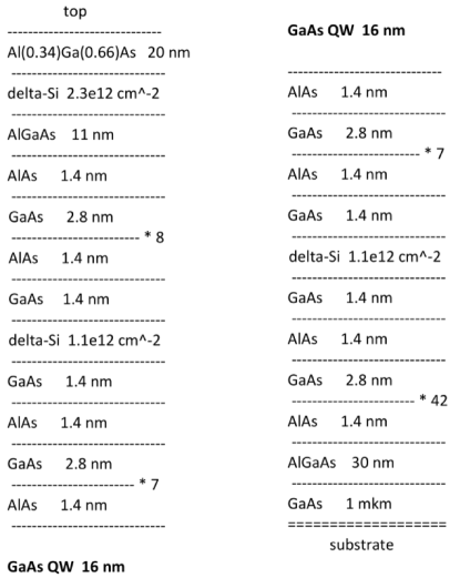
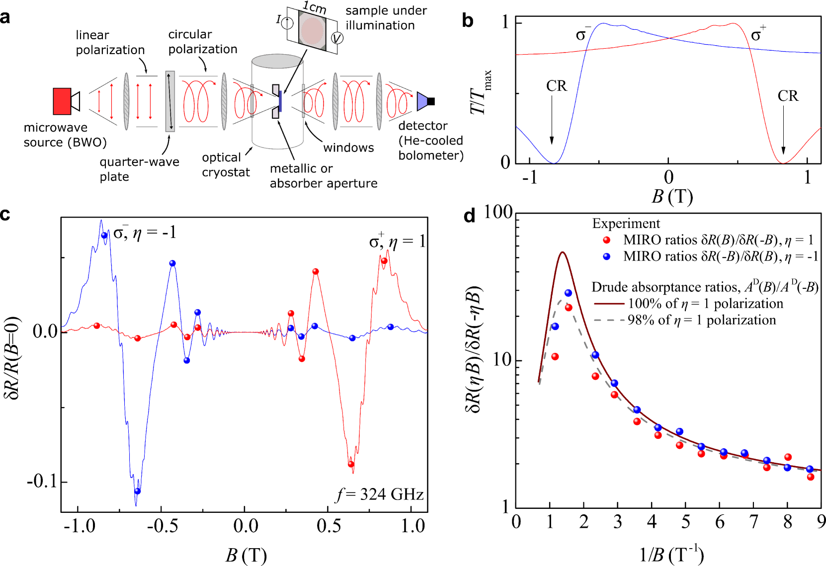
Methods.– Our simultaneous transmittance and photoresistance measurements, see Fig. 1 (a), were carried out on a heterostructure containing 2DES in a selectively doped 16-nm GaAs quantum well with AlAs/GaAs superlattice barriers grown by molecular beam epitaxy SM (1); Baba et al. (1983); Friedland et al. (1996); Umansky et al. (2009); Manfra (2014). The lateral size of the van der Pauw sample was mm2, with ohmic Ge/Au/Ni/Au contacts at the corners. The electron density and mobility extracted from magnetotransport measurements were cm-2 and cm2/Vs. The sample was irradiated from the substrate side through circular metallic (Fig. 2) or absorber (Fig. 1) apertures of varying diameter. Backward-wave oscillators (BWO) were used as stable sources of normally incident continuous monochromatic radiation with frequency in the range between 50 and GHz. A split-coil superconducting magnet provided a magnetic field oriented perpendicular to the sample surface. The photoresistance (the difference of the resistance signals in the presence and absence of irradiation) was measured using the double-modulation technique SM (1). In parallel with the photoresistance, the transmittance through the sample was measured using a liquid He-cooled bolometer. All presented results were obtained at temperature of K.
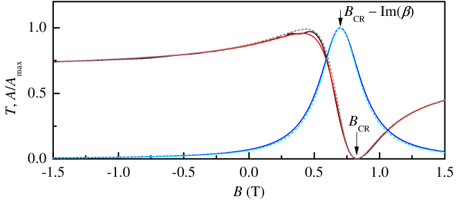
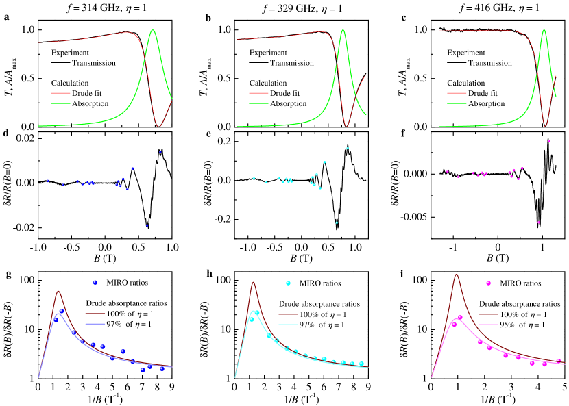
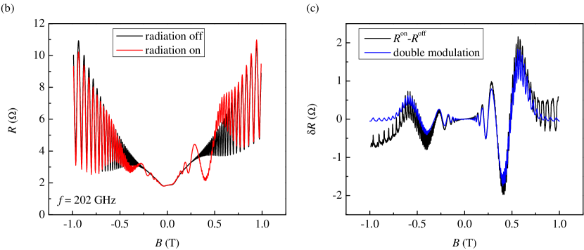
Helicity dependence of MIRO, transmittance, and absorptance.– Figure 1 shows representative examples of simultaneously measured transmittance and photoresistance , recorded for both helicities of GHz circularly polarized radiation. The transmittance traces in panel (b) display strong dips at the CRs, , marked by arrows. The absence of any features at opposite confirms a high degree of the circular polarization in the transmitted signal. The photoresistance in Fig. 1 (c) shows pronounced MIRO governed by the ratio of the radiation and cyclotron frequencies. In sharp contrast to previous reports Smet et al. (2005); Herrmann et al. (2016), our results reveal a high asymmetry of MIRO with respect to polarity of which inverts with the change of radiation helicity . This is one of our central observations which unequivocally demonstrates that the long debated polarization immunity is not a generic property of MIRO in solid-state 2DES.
Moreover, we find an excellent quantitative agreement between the shape of CR in measured and the -asymmetry of the MIRO signal, in full accordance with Eq. (1). This agreement is illustrated in Fig. 1 (d) where we plot ratios of MIRO signal between CR-active and CR-passive polarities of , for both helicities. Here we use values of at the opposite-lying MIRO extrema marked by circles in panel (c). It is seen that the asymmetry is strongly enhanced in the region of CR reaching values of for the main MIRO extrema around . Solid and dashed lines show the corresponding ratio of the Drude absorption calculated using parameters extracted from the shape of in panel (b), for 100% right circular polarization and for 98% to 2% mixture of right and left polarizations, respectively. An almost perfect agreement with Eq. (1) demonstrates an ultimate sensitivity of MIRO to circular polarization. It is important to emphasize that this comparison, detailed below, does not assume any specific microscopic mechanism of MIRO. It rather establishes that polarization dependences of MIRO and of Drude absorption are the same.
Modelling of transmittance and absorptance.– As detailed in Supplemental Material SM (1), the shape of can be well reproduced using the standard expression, , with the complex dynamic conductivity of 2DES taken in the classical Drude form, , and with two complex parameters describing the Fabry-Pérot interference due to multiple reflections in the GaAs substrate. Here, the interference phase is given by the ratio of the sample thickness and the wavelength , is the refractive index of the substrate, and is the impedance of free space. The resulting Drude transmittance and Drude absorptance, , are given by
| (2) |
| (3) |
where and . The shape of measured in Fig. 1 is well reproduced by Eq. (2) using T extracted from magnetotransport measurements, T corresponding to the cyclotron mass , and T SM (1). On top of smooth Drude transmittance, our high resolution measurements are able to resolve weak quantum -oscillations studied in Ref. [Savchenko et al., 2021]. The extracted parameters are used in calculated ratios in Fig. 1(d), which establish the validity of Eq. (1).
Aperture dependence of the polarization-sensitive measurements. –
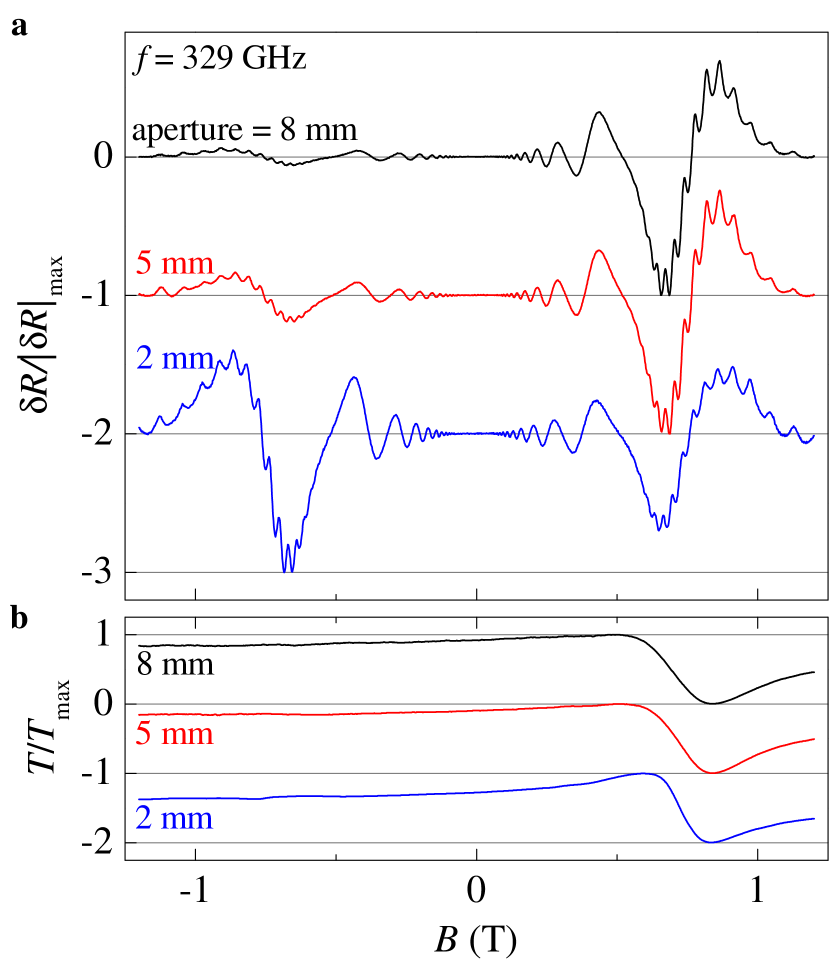
While the strong helicity dependence is unambiguously demonstrated in Fig. 1, our further measurements have shown that this result can be strongly affected by metallic aperture that is typically used to avoid illumination of the contacts and sample edges in this type of experiments. To explore this issue we performed a detailed study of the effect of aperture diameter on the helicity dependence. Figure 2 shows the -dependencies of the photoresistance (top panel) and transmittance (bottom panel) measured at 329 GHz ( mm) with varying diameter of the aperture. Top panel demonstrates that the MIRO asymmetry strongly depends on the diameter of aperture when other experimental parameters are kept unchanged. We clearly see that the MIRO ratio is the largest for 8 mm aperture and tends towards unity for the diaphragms smaller than the estimated size of the focal spot of about 4 mm. On the contrary, the transmittance signal in the bottom panel does not considerably change for different apertures.
We explain such behavior as follows: The MIRO signal is sensitive to the polarization of the local electromagnetic field. If the aperture size is too small such that the radiation interacts with the metallic edges, then the local polarization in the nearby 2DES will be linear regardless of the incident degree of the circular polarization. This follows from the boundary conditions requiring that the –field can only have a normal component at the metal surface Landau and Lifshitz (Pergamon, Oxford, 1984). Therefore, the radiation that reaches the metal aperture results in a distortion of the local polarization and, consequently, of the detected photoresistance signal reflecting the local absorption.
The appearance of local linearly-polarized electric field can be understood considering a circularly polarized wave irradiating a circular metallic waveguide, see Supplemental Material SM (1) for details. The distribution of local circularly-rotating electric fields that fulfil the boundary conditions is given by:
| (4) |
Here are the Bessel functions of -th order, is the radial wavevector of the lowest propagating mode in a circular waveguide, are right- and left-rotating circular fields, is the amplitude of the incident electric field.
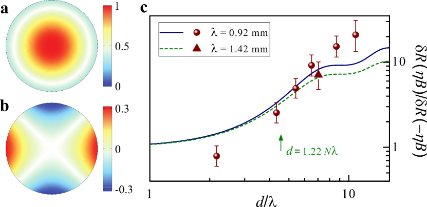
The distributions of the circular components and are shown in Fig. 3 (a) and (b), respectively. The amplitude of polarization is rotationally symmetric across the waveguide with a flat maximum in the middle. Obviously, this is the same polarization as that of the incident circularly-polarized beam. On the contrary, the is zero in the middle of the waveguide and changes sign four times along the wall of the waveguide.
According to the Huygens-Fresnel principle the amplitude of the transmitted wave is proportional to the sum of secondary sources from all points on the wavefront. After integration of the fields, negative and positive regions cancel each other. Thereby, the distorted polarization is absent in the far field and produces no signal at the bolometer. That is the reason why all curves in Fig. 2 (b) show only one well-defined CR. In contrast to the transmittance, the absorbed power and MIRO are proportional to the square of the local near field. Therefore, the response to the distorted polarization does not vanish in resistivity signal.
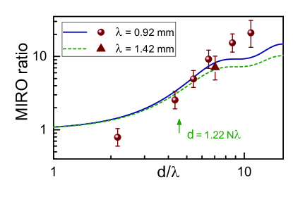
In Fig. 3 (c) we show the ratio of MIRO amplitudes for active and passive circular polarizations as function of , where is the diameter of the metallic aperture and is the radiation wavelength. In order to estimate the ratio of intensities for active () and passive () circular polarizations we calculate the power ratio that is cut off by the aperture in the focus of the lens. The radial distribution of the field in the focus Born and Wolf (2000) is given by
| (5) |
where is the normalized aperture diameter, and is the -number of the focusing lens with diameter cm and focal length cm. Model curves in Fig. 3 (c) are calculated using Eq. (5) and taking (solid line, mm) and (dashed line, mm). The difference in the amplitudes originates from the frequency dependence of the MIRO ratio from Eq. (3), . This yields a reasonable fit to the experimental points in spite of qualitative character of the arguments. Indeed, the MIRO ratio tends to unity for apertures below the diffraction spot indicated by the arrow.
Discussion. – Our results demonstrate that the long-debated polarization immunity is not universal intrinsic property of MIRO in solid-state 2DES: (i) we detect strong intrinsic helicity dependence of MIRO that accurately follows the regular CR in the Drude absorption and (ii) we show that extrinsic factors deteriorating the polarization state of radiation can be avoided using sufficiently large samples and apertures. On the other hand, very recent experiments Mönch et al. (2022), where several samples of similar size were studied at terahertz frequencies, revealed a helicity immunity of the resonant photoresponse which directly measures the CR absorption via heating of 2DES. This clearly indicates that the helicity immunity problem remains and, moreover, has a more fundamental character, i.e. is not limited to MIRO. A possible reason Mönch et al. (2022) is that in particular 2DES the internal high-frequency response of electrons to a uniform external field can be essentially nonuniform, producing an intrinsic helicity distortion of the near field in the vicinity of individual strong scattering centers or inhomogeneities. Altogether, these results indicate an interesting research direction deserving further experimental and theoretical efforts.
Conclusions. – In the sub-terahertz frequency range we observe MIRO in GaAs/AlGaAs 2DES that are ultimately sensitive to the helicity of circularly polarized radiation. The helicity dependence accurately follows that of the Drude absorption, in full agreement with natural expectations. Moreover, we demonstrate that observation of intrinsic polarization dependence requires large sample sizes and large apertures. Otherwise, the near field reaching 2DES has a significant component of opposite helicity, which does not affect the transmittance measured in the far field, but essentially changes the asymmetry of the MIRO signal leading to apparent polarization immunity. Our results provide the opportunity to reliably test other systems potentially featuring an intriguing intrinsic polarization immunity of the photoresponse.
Acknowledgements. – The authors thank E. Mönch, D. A. Kozlov, D. G. Polyakov, and J. H. Smet for valuable discussions. We are grateful to A. K. Bakarov and A. A. Bykov for providing high-quality GaAs/AlGaAs samples. We acknowledge the financial support of the Austrian Science Funds (I 3456-N27, I 5539-N), and of the German Research Foundation (Deutsche Forschungsgemeinschaft) via grant DM 1/5-1 (I.A.D.) and via sub-project A04 of the Project-ID 314695032 – SFB 1277 (S.D.G).
References
- Dmitriev et al. (2012) I. A. Dmitriev, A. D. Mirlin, D. G. Polyakov, and M. A. Zudov, “Nonequilibrium phenomena in high Landau levels,” Rev. Mod. Phys. 84, 1709 (2012).
- Zudov et al. (2001a) M. A. Zudov, R. R. Du, J. A. Simmons, and J. L. Reno, “Shubnikov – de Haas-like oscillations in millimeterwave photoconductivity in a high-mobility two-dimensional electron gas,” Phys. Rev. B 64, 201311(R) (2001a).
- Mani et al. (2002) R. G. Mani, J. H. Smet, K. von Klitzing, V. Narayanamurti, W. B. Johnson, and V. Umansky, “Zero-resistance states induced by electromagnetic-wave excitation in GaAs/AlGaAs heterostructures,” Nature 420, 646 (2002).
- Zudov et al. (2003) M. A. Zudov, R. R. Du, L. N. Pfeiffer, and K. W. West, “Evidence for a new dissipationless effect in 2D electronic transport,” Phys. Rev. Lett. 90, 046807 (2003).
- Yang et al. (2003) C. L. Yang, M. A. Zudov, T. A. Knuuttila, R. R. Du, L. N. Pfeiffer, and K. W. West, “Observation of microwave-induced zero-conductance state in Corbino rings of a two-dimensional electron system,” Phys. Rev. Lett. 91, 096803 (2003).
- Zudov et al. (2001b) M. A. Zudov, I. V. Ponomarev, A. L. Efros, R. R. Du, J. A. Simmons, and J. L. Reno, “New class of magnetoresistance oscillations: interaction of a two-dimensional electron gas with leaky interface phonons,” Phys. Rev. Lett. 86, 3614 (2001b).
- Yang et al. (2002) C. L. Yang, J. Zhang, R. R. Du, J. A. Simmons, and J. L. Reno, “Zener tunneling between Landau orbits in a high-mobility two-dimensional electron gas,” Phys. Rev. Lett. 89, 076801 (2002).
- Zhang et al. (2008) W. Zhang, M. A. Zudov, L. N. Pfeiffer, and K. W. West, “Resonant phonon scattering in quantum Hall systems driven by dc electric fields,” Phys. Rev. Lett. 100, 036805 (2008).
- Zhang et al. (2007) W. Zhang, M. A. Zudov, L. N. Pfeiffer, and K. W. West, “Resistance oscillations in two-dimensional electron systems induced by both ac and dc fields,” Phys. Rev. Lett. 98, 106804 (2007).
- Wiedmann et al. (2010) S. Wiedmann, G. M. Gusev, O. E. Raichev, A. K. Bakarov, and J. C. Portal, “Microwave zero-resistance states in a bilayer electron system,” Phys. Rev. Lett. 105, 026804 (2010).
- Smet et al. (2005) J. H. Smet, B. Gorshunov, C. Jiang, L. Pfeiffer, K. West, V. Umansky, M. Dressel, R. Meisels, F. Kuchar, and K. von Klitzing, “Circular-polarization-dependent study of the microwave photoconductivity in a two-dimensional electron system,” Phys. Rev. Lett. 95, 116804 (2005).
- Dorozhkin et al. (2011) S. I. Dorozhkin, L. Pfeiffer, K. West, K. von Klitzing, and J. H. Smet, “Random telegraph photosignals in a microwave-exposed two-dimensional electron system,” Nat. Phys. 7, 336 (2011).
- Bykov et al. (2010) A. A. Bykov, I. V. Marchishin, A. V. Goran, and D. V. Dmitriev, “Microwave induced zero-conductance state in a Corbino geometry two-dimensional electron gas with capacitive contacts,” Appl. Phys. Lett. 97, 082107 (2010).
- Levin et al. (2015) A. D. Levin, Z. S. Momtaz, G. M. Gusev, O. E. Raichev, and A. K. Bakarov, “Microwave-induced magneto-oscillations and signatures of zero-resistance states in phonon-drag voltage in two-dimensional electron systems,” Phys. Rev. Lett. 115, 206801 (2015).
- Dorozhkin et al. (2016) S. I. Dorozhkin, A. A. Kapustin, V. Umansky, K. von Klitzing, and J. H. Smet, “Microwave-induced oscillations in magnetocapacitance: Direct evidence for nonequilibrium occupation of electronic states,” Phys. Rev. Lett. 117, 176801 (2016).
- Herrmann et al. (2016) T. Herrmann, I. A. Dmitriev, D. A. Kozlov, M. Schneider, B. Jentzsch, Z. D. Kvon, P. Olbrich, V. V. Bel’kov, A. Bayer, D. Schuh, D. Bougeard, T. Kuczmik, M. Oltscher, D. Weiss, and S. D. Ganichev, “Analog of microwave-induced resistance oscillations induced in GaAs heterostructures by terahertz radiation,” Phys. Rev. B 94, 081301(R) (2016).
- Shi et al. (2017) Q. Shi, M. A. Zudov, I. A. Dmitriev, K. W. Baldwin, L. N. Pfeiffer, and K. W. West, “Fine structure of high-power microwave-induced resistance oscillations,” Phys. Rev. B 95, 041403(R) (2017).
- Konstantinov et al. (2013) D. Konstantinov, Yu. Monarkha, and K. Kono, “Effect of Coulomb interaction on microwave-induced magnetoconductivity oscillations of surface electrons on liquid helium,” Phys. Rev. Lett. 111, 266802 (2013).
- Zudov et al. (2014) M. A. Zudov, O. A. Mironov, Q. A. Ebner, P. D. Martin, Q. Shi, and D. R. Leadley, “Observation of microwave-induced resistance oscillations in a high-mobility two-dimensional hole gas in a strained quantum well,” Phys. Rev. B 89, 125401 (2014).
- Kärcher et al. (2016) D. F. Kärcher, A. V. Shchepetilnikov, Yu. A. Nefyodov, J. Falson, I. A. Dmitriev, Y. Kozuka, D. Maryenko, A. Tsukazaki, S. I. Dorozhkin, I. V. Kukushkin, M. Kawasaki, and J. H. Smet, “Observation of microwave induced resistance and photovoltage oscillations in MgZnO/ZnO heterostructures,” Phys. Rev. B 93, 041410(R) (2016).
- Yamashiro et al. (2015) R. Yamashiro, L. V. Abdurakhimov, A. O. Badrutdinov, Yu. P. Monarkha, and D. Konstantinov, “Photoconductivity response at cyclotron-resonance harmonics in a nondegenerate two-dimensional electron gas on liquid helium,” Phys. Rev. Lett. 115, 256802 (2015).
- Zadorozhko et al. (2018) A. A. Zadorozhko, Yu. P. Monarkha, and D. Konstantinov, “Circular-polarization-dependent study of microwave-induced conductivity oscillations in a two-dimensional electron gas on liquid helium,” Phys. Rev. Lett. 120, 046802 (2018).
- Otteneder et al. (2018) M. Otteneder, I. A. Dmitriev, S. Candussio, M. L. Savchenko, D. A. Kozlov, V. V. Bel’kov, Z. D. Kvon, N. N. Mikhailov, S. A. Dvoretsky, and S. D. Ganichev, “Sign-alternating photoconductivity and magnetoresistance oscillations induced by terahertz radiation in HgTe quantum wells,” Phys. Rev. B 98, 245304 (2018).
- Friess et al. (2020) B. Friess, I. A. Dmitriev, V. Umansky, L. Pfeiffer, K. West, K. von Klitzing, and J. H. Smet, “Acoustoelectric study of microwave-induced current domains,” Phys. Rev. Lett. 124, 117601 (2020).
- Tabrea et al. (2020) D. Tabrea, I. A. Dmitriev, S. I. Dorozhkin, B. P. Gorshunov, A. V. Boris, Y. Kozuka, A. Tsukazaki, M. Kawasaki, K. von Klitzing, and J. Falson, “Microwave response of interacting oxide two-dimensional electron systems,” Phys. Rev. B 102, 115432 (2020).
- Mönch et al. (2020) E. Mönch, D. A. Bandurin, I. A. Dmitriev, I. Y. Phinney, I. Yahniuk, T. Taniguchi, K. Watanabe, P. Jarillo-Herrero, and S. D. Ganichev, “Observation of terahertz-induced magnetooscillations in graphene,” Nano Letters 20, 5943 (2020).
- Kumaravadivel et al. (2019) P. Kumaravadivel, M. T. Greenaway, D. Perello, A. Berdyugin, J. Birkbeck, J. Wengraf, S. Liu, J. H. Edgar, A. K. Geim, L. Eaves, and R. Krishna Kumar, “Strong magnetophonon oscillations in extra-large graphene,” Nat. Commun. 10, 3334 (2019).
- Savchenko et al. (2020) M. L. Savchenko, M. Otteneder, I. A. Dmitriev, N. N. Mikhailov, Z. D. Kvon, and S. D. Ganichev, “Terahertz photoresistivity of a high-mobility 3D topological insulator based on a strained HgTe film,” Appl. Phys. Lett. 117, 201103 (2020).
- Ryzhii (1970) V. I. Ryzhii, “Photoconductivity characteristics in thin films subjected to crossed electric and magnetic fields,” Sov. Phys. Solid State 11, 2078 (1970).
- Durst et al. (2003) A. C. Durst, S. Sachdev, N. Read, and S. M. Girvin, “Radiation-induced magnetoresistance oscillations in a 2D electron gas,” Phys. Rev. Lett. 91, 086803 (2003).
- Dmitriev et al. (2003) I. A. Dmitriev, A. D. Mirlin, and D. G. Polyakov, “Cyclotron-resonance harmonics in the ac response of a 2D electron gas with smooth disorder,” Phys. Rev. Lett. 91, 226802 (2003).
- Andreev et al. (2003) A. V. Andreev, I. L. Aleiner, and A. J. Millis, “Dynamical symmetry breaking as the origin of the zero-dc-resistance state in an ac-driven system,” Phys. Rev. Lett. 91, 056803 (2003).
- Vavilov and Aleiner (2004) M. G. Vavilov and I. L. Aleiner, “Magnetotransport in a two-dimensional electron gas at large filling factors,” Phys. Rev. B 69, 035303 (2004).
- Dmitriev et al. (2005) I. A. Dmitriev, M. G. Vavilov, I. L. Aleiner, A. D. Mirlin, and D. G. Polyakov, “Theory of microwave-induced oscillations in the magnetoconductivity of a two-dimensional electron gas,” Phys. Rev. B 71, 115316 (2005).
- Vavilov et al. (2007) M. G. Vavilov, I. L. Aleiner, and L. I. Glazman, “Nonlinear resistivity of a two-dimensional electron gas in a magnetic field,” Phys. Rev. B 76, 115331 (2007).
- Dmitriev et al. (2009) I. A. Dmitriev, M. Khodas, A. D. Mirlin, D. G. Polyakov, and M. G. Vavilov, “Mechanisms of the microwave photoconductivity in two-dimensional electron systems with mixed disorder,” Phys. Rev. B 80, 165327 (2009).
- Raichev (2008) O. E. Raichev, “Magnetic oscillations of resistivity and absorption of radiation in quantum wells with two populated subbands,” Phys. Rev. B 78, 125304 (2008).
- Monarkha and Konstantinov (2019) Y. Monarkha and D. Konstantinov, “Magneto-oscillations and anomalous current states in a photoexcited electron gas on liquid helium,” J. Low Temp. Phys. 197, 208 (2019).
- Dmitriev (2019) I. A. Dmitriev, “Self-oscillations and noise-induced flips of spontaneous electric field in microwave-induced zero resistance state,” EPL (Europhysics Letters) 126, 57004 (2019).
- Greenaway et al. (2019) M. T. Greenaway, R. Krishna Kumar, P. Kumaravadivel, A. K. Geim, and L. Eaves, “Magnetophonon spectroscopy of Dirac fermion scattering by transverse and longitudinal acoustic phonons in graphene,” Phys. Rev. B 100, 155120 (2019).
- Raichev and Zudov (2020) O. E. Raichev and M. A. Zudov, “Effect of Berry phase on nonlinear response of two-dimensional fermions,” Phys. Rev. Research 2, 022011 (2020).
- Dmitriev et al. (2004) I. A. Dmitriev, A. D. Mirlin, and D. G. Polyakov, “Oscillatory ac conductivity and photoconductivity of a two-dimensional electron gas: quasiclassical transport beyond the Boltzmann equation,” Phys. Rev. B 70, 165305 (2004).
- Chepelianskii and Shepelyansky (2009) A. D. Chepelianskii and D. L. Shepelyansky, “Microwave stabilization of edge transport and zero-resistance states,” Phys. Rev. B 80, 241308(R) (2009).
- Mikhailov (2011) S. A. Mikhailov, “Theory of microwave-induced zero-resistance states in two-dimensional electron systems,” Phys. Rev. B 83, 155303 (2011).
- Beltukov and Dyakonov (2016) Y. M. Beltukov and M. I. Dyakonov, “Microwave-induced resistance oscillations as a classical memory effect,” Phys. Rev. Lett. 116, 176801 (2016).
- SM (1) See Supplemental Material after the main text for a more detailed analysis of helicity dependence of transmittance, Drude absorption, and MIRO including data measured at different frequencies and the aperture impact on transmittance and MIRO, for the power dependence of MIRO, the sample design, and additional details of measurements.
- Baba et al. (1983) T. Baba, T. Mizutani, and M. Ogawa, “Elimination of persistent photoconductivity and improvement in Si activation coefficient by Al spatial separation from Ga and Si in Al-Ga-As:Si solid system – a novel short period AlAs/n-GaAs superlattice,” Japanese Journal of Applied Physics 22, L627 (1983).
- Friedland et al. (1996) K.-J. Friedland, R. Hey, H. Kostial, R. Klann, and K. Ploog, “New concept for the reduction of impurity scattering in remotely doped GaAs quantum wells,” Phys. Rev. Lett. 77, 4616 (1996).
- Umansky et al. (2009) V. Umansky, M. Heiblum, Y. Levinson, J. Smet, J. Nübler, and M. Dolev, “MBE growth of ultra-low disorder 2DEG with mobility exceeding cm2/Vs,” J. Cryst. Growth 311, 1658 (2009).
- Manfra (2014) M. J. Manfra, “Molecular beam epitaxy of ultra-high-quality AlGaAs/GaAs heterostructures: Enabling physics in low-dimensional electronic systems,” Annu. Rev. Condens. Matter Phys. 5, 347–373 (2014).
- Savchenko et al. (2021) M. L. Savchenko, A. Shuvaev, I. A. Dmitriev, A. A. Bykov, A. K. Bakarov, Z. D. Kvon, and A. Pimenov, “High harmonics of the cyclotron resonance in microwave transmission of a high-mobility two-dimensional electron system,” Phys. Rev. Res. 3, L012013 (2021).
- Landau and Lifshitz (Pergamon, Oxford, 1984) L. D. Landau and E. M. Lifshitz, Electrodynamics of Continuous Media (Pergamon, Oxford, 1984).
- Born and Wolf (2000) M. Born and E. Wolf, Principles of Optics: Electromagnetic Theory of Propagation, Interference and Diffraction of Light (Cambridge University Press, 2000).
- Mönch et al. (2022) E. Mönch, P. Euringer, G.-M. Hüttner, I. A. Dmitriev, D. Schuh, M. Marocko, J. Eroms, D. Bougeard, D. Weiss, and S. D. Ganichev, “Circular polarization immunity of the cyclotron resonance photoconductivity in two-dimensional electron systems,” arXiv:2206.07617 (2022).
SUPPLEMENTAL MATERIAL
S1 Helicity dependence of transmittance, Drude absorptance, and MIRO
The main experimental finding of our work is strong helicity dependence of MIRO signal in the studied 2DES. It sharply contrasts all previous studies of solid-state 2DES which reported polarization immunity of MIRO in the case of circularly polarized radiation. Thus, our findings prove that the polarization immunity is not a universal intrinsic property of MIRO but rather a sample-dependent property possibly reflecting different disorder realization in particular structures.
Moreover, for our sample we are able to demonstrate that, in agreement with theoretical predictions Dmitriev et al. (2012), the ratio of measured MIRO signal for opposite magnetic field polarities accurately follows that of the Drude absorptance , as long as extrinsic electrodynamic effects related to too small aperture or sample size in comparison to the laser beam and wavelength are suppressed, see Sec. S4. As detailed below, this conclusion is based on analysis of simultaneously measured transmittance which readily provides the parameters of the corresponding taking into account both strong reflection of radiation from 2DES in the region of CR and Fabry-Pérot interference in the dielectric substrate. For completeness, an explicit derivation of the corresponding standard expressions for transmittance and absorptance for uniform 2DES from Maxwell equations is provided in Sec. S3.
In Fig. S1 we show the transmittance data presented in Fig. 1 of main text together with the Drude fit obtained using Eq. (2) of the main text (shown below and derived in Sec. S3):
| (S1) |
In the classical Drude approximation (S1), the shape of transmittance is fixed by the position of the CR, T, which can be accurately determined from the position of the deep minimum in measured ; by the mobility cm2/m s, which was extracted from dark resistance measurements, see Sec. S8, and by complex fitting parameter , see the main text and Sec. S3, which provides a combined description of strong reflection of radiation from 2DES in the region of CR and Fabry-Pérot interference due to multiple reflections in the dielectric substrate. Fit of the measured transmittance using T is shown by red solid line. It is seen that the shape of measured (black line) is well captured by Eq. (S1), apart from weak quantum oscillations coupled to harmonics of CR which were studied in our previous work Savchenko et al. (2021) and are not directly relevant to the present discussion of helicity dependence of MIRO. A dashed line in Fig. S1 shows obtained using Eq. (S1) where all parameters are kept the same apart from , that is set to zero. The dashed and solid red lines are very close to each other, which reflects the fact that in our high-mobility and high-density 2DES, the CR broadening is mainly due to strong reflection of radiation from 2DES and not due to impurity scattering, T.
The analysis of readily gives the corresponding shape of the Drude absorptance,
| (S2) |
illustrated by blue line in Fig. S1. Similar to transmittance, the shape of (normalized to its maximal value in Fig. S1) is almost insensitive to scattering. This is illustrated by dashed blue line showing in the clean limit . The value is, of course, sensitive to scattering, but this does not affect the helicity dependence of absorptance and MIRO and thus is irrelevant for our discussion. It is also worth mentioning that the Fabry-Pérot interference in the substrate, producing an asymmetric shape of in the case of , also leads to a significant shift of the CR maximum in absorption from to , see arrows in Fig. S1.
According to theoretical predictions Dmitriev et al. (2012), MIRO in high-mobility 2DES in the case of circular polarization can be represented as a product
| (S3) |
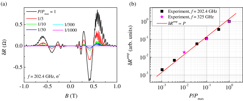
where and are intensity and helicity of the incident wave, is the corresponding Drude absorption (S2), and is a mechanism-specific function which describes magnetooscillations and depends only on the magnitude but not polarity of the magnetic field applied at normal to the 2DES plane. From the theoretical viewpoint, the relation (S3) in high-mobility 2DES remains valid as long as the intensity is low enough, such that the photoresponce remains linear, . This linearity in our study is confirmed by measurements of MIRO at different power levels of the source, see Sec. S5. The form of MIRO in Eq. (S3) implies that the -asymmetry (and, thus, the helicity dependence) of the Drude absorption and MIRO should be the same:
| (S4) |
see Eq. (1) of the main text. This relation does not involve the mechanism-specific function and thus can be verified independently, without full analysis of the detected MIRO within specific mechanisms which will be presented elsewhere.
Comparison of the MIRO and Drude absorption ratios in Fig. 1(d) demonstrates that the relation (S4) holds for our data. We attribute somewhat lower MIRO ratios in comparison to the Drude absorption ratios calculated for 100 % circular polarization to the presence of a small component with an opposite helicity in the incoming radiation. To estimate the amount of such admixture, we also calculate the absorption ratio for an imperfect polarization,
| (S5) |
and find that admixture of 2 % of circular polarization, i.e. and , is sufficient to perfectly fit the data for , see dashed line in Fig. 1(d).
The data in Fig. 1 were obtained using the absorbing aperture of mm diameter at Ghz. Figure S2 shows several further examples of the analysis presented above, but now for data obtained with metallic aperture of mm diameter at three different frequencies of radiation. Also here we observe an excellent agreement between helicity dependence (-asymmetry) of MIRO and absorption. The best fit in the region of CR is obtained for using an admixture of 3% (for two lower ) or 5% (for the highest ) of component in the intensity of incident wave. Apart from confirmation of the results in Fig. 1, it shows that using mm metallic aperture at above GHz is sufficient to suppress the extrinsic effects capable to mask strong intrinsic helicity dependence of MIRO. These effects, see Sec. S4, become strong at lower frequencies, see Sec. S6, or for smaller aperture size, see Fig. 2 of the main text. Thus, our results, establishing the conditions necessary to avoid deterioration of the polarization state of radiation reaching 2DES, provide the opportunity to reliably test other systems potentially featuring an intriguing intrinsic polarization immunity of the photoresponse.
S2 Transmittance, MIRO, and MIRO ratios at different frequencies
S3 Derivation of expression for transmission of a plane electromagnetic wave though a sample containing a uniform isotropic 2DES
Here we apply a standard theory of transmission though a stratified media to our case of a circularly polarised wave normally incident on a sample containing a uniform isotropic 2DES, and obtain expressions for transmittance and absorptance used in the main text and Sec. S1.
Consider an incident plane electromagnetic wave with electric field given by the real part of where the polarization vector corresponds to a circular polarization with helicity . The wave is normally incident on the back (substrate) side of the sample at . The sample is modelled as a dielectric slab with refractive index and thickness that contains a 2DES at a negligibly small distance from the opposite front interface at . The wave is partially transmitted and partially reflected at both back and front interfaces. By continuity of the tangential electric field at all interfaces (note that normal components of the high-frequency field do not appear in this problem in the case of a uniform 2DES), the electric field acting on electrons in this setup is given by , and the same transmission amplitude determines the transmittance . For a uniform isotropic 2DES, characterised by a local dynamic conductivity tensor with components and , the sense of rotation of fields in all reflected and transmitted partial waves is the same, and coincides with that of the induced electrical current in 2DES, . Indeed, the conductivity tensor is diagonal in the helicity basis, with . Therefore, propagation of both circularly polarized modes can be considered independently. The problem is reduced to determination of the scalar coefficients in electric and magnetic field distributions in the whole space,
| (S6) |
where is the vacuum impedance, and the wave vector inside and outside the sample. According to the Maxwell equations, both and are continuous at the dielectric interfaces. Across the 2DES plane, the magnetic field experience a jump given by . Implementing these boundary conditions, one arrives at a matrix equation for a vector constructed from the electric and magnetic field amplitudes. This equation, explicitly given by
| (S7) |
relates the value of for the wave transmitted through the front interface to combining the incident and reflected waves at the back interface. Two transfer matrices and describe propagation through the dielectric substrate and 2DES, correspondingly. Solution of Eq. (S7) yields the standard expression for transmittance,
| (S8) |
as well as related expressions for reflectance and absorptance .
With the complex dynamic conductivity of 2DES taken in the classical Drude form, , from Eq. (S8) one obtains Eqs. (2) and (3) of the main text for the Drude transmittance and absorptance . In Sec. S1, these expressions are used to demonstrate that the -asymmetry of the Drude absorptance and MIRO in our sample are the same, as long as extrinsic electrodynamic effects are excluded, see Sec. S4. In Sec. S1, it is also demonstrated that the shape of both and in our sample are almost insensitive to the impurity scattering, and can well reproduced using conductivity of a clean 2DES, see dashed lines in Fig. S1.
S4 Influence of extrinsic factors which explains differences in polarization dependence of transmission and photoresistance
Mathematically, the appearance of local linearly-polarized electric field can be understood considering a circularly polarized wave falling on a circular metallic waveguide. Although in the general case several eigenmodes of the waveguide will be excited, the mode closest to a circular plane wave is the TE1,1 mode. Electric fields of this mode in cylindrical coordinates are given by (common factor is ):
| (S9) | |||||
Here are the Bessel functions of the -th order, for TE1,1 mode, the radial and axial wavevectors are connected by the dispersion relation and the radial wavevector is given by with the first root of the derivative of the first Bessel function .
The calculated field lines of electric (orange lines) and magnetic (green lines) fields of TE1,1 mode are shown in the left panel of Fig. S3. The electric field lines start and end at the metallic surfaces and are perpendicular to the cylinder axis. This field distribution rotates clockwise as a function of time. In the center of the waveguide the TE1,1 mode reproduces exactly the circularly polarized wave and fulfils the boundary conditions of a normal electric field at the edges. Locally, electric fields can be decomposed into a sum of left-rotation and right-rotating circular fields via . Here and are the fields in Eq. (S9) expressed in the cartesian coordinates. Finally, the momentarily distribution of local circularly-rotating fields are given by:
| (S10) |
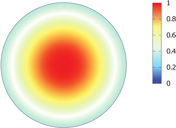
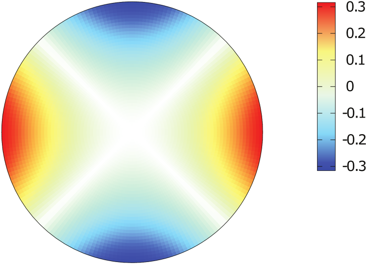
The distributions of the circular components and are shown in Fig. S3 in the middle and right panels, respectively. The amplitude of polarization is rotation-symmetric across the waveguide with a flat maximum in the middle. Obviously, this is the same polarization as that of incident circularly-polarized beam. On the contrary, the polarization is zero in the middle of the waveguide and changes sign four times along the wall of the waveguide (see red and blue regions in the right panel). This is the distorted polarization due to the boundary condition at the metal surface.
Importantly, the distorted polarization is absent in the far field and produces zero signal at the bolometer. According to the Huygens-Fresnel principle the amplitude of the transmitted wave is proportional to the sum of secondary sources from all of the points on the wavefront. After integration of the fields, negative and positive regions cancel each other. Contrary to a linear response in transmittance, the MIRO signal reflects local near field containing both circular components. Therefore, the response to the distorted polarization does not vanish in MIRO signal.
Solid symbols in Fig. S4 show the ratio of MIRO amplitudes for active and passive circular polarizations as function of the size of the aperture. To compare the results in different experiments we plot MIRO as a function of ratio , where is the diameter of the metallic diaphragm and is the wavelength. The data have been obtained for GHz (spheres) and GHz (triangles). Although an estimate of the local field distributions based on the TE1,1 mode provides a qualitative explanation of the observed effect, it does explain the relation between MIRO ratio and the diameter of the aperture. In order to get an estimate of this relation we suggest to attribute it to a power ratio that is cut off by the diaphragm in the focus of the lens. The radial distribution of the field in the focus Born and Wolf (2000) is given by
| (S11) |
where is the renormalized ratio of the diaphragm diameter and the wavelength . Here is the -number of the focusing lens with diameter cm and focal length cm. We assume that the ratio of the circularly- and linearly-polarized light in the sample plane is equal to the fraction of the power transmitted through the diaphragm. Model curves in Fig. S4 are calculated using Eq. (S11) and taking (solid line) and (dashed line) for GHz and GHz, respectively. The difference in the amplitudes originates from the frequency dependence of the MIRO ratio Herrmann et al. (2016) . We conclude a reasonable fit to the experimental points in spite of qualitative character of the given arguments.
S5 Power dependence of MIRO
S6 Transmittance and MIRO at different frequencies
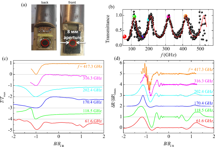
The sample insert consists of a fixed part with the beam aperture and the movable part with the sample. The sample is fixed on a thin (6 to 13 m) Mylar foil which is clipped to the movable rod of the insert (Fig. S6 (a)).
In Fig. S6 (b) we show the frequency dependence of transmittance at which clearly demonstrates the Fabry-Pérot interference due to internal reflections between back and front interfaces of the sample.Black spheres represent the experimental data, while the red line is calculated according to Eq. (2) of the main text (or Eq. (S8) in SM). Big color spheres correspond to 6 frequencies at which transmittance and MIRO are measured on panels (c) and (d).
In Fig. S6 (c) and (d) we show the dependences of normalized transmittance and photoresistance on normalized measured using 8 mm aperture and circularly polarized radiation. Panel (d) demonstrates that the MIRO asymmetry strongly depends on the frequency – it increases as frequency goes up. This observation can be explained by the influence of the metallic aperture at low ratios of the aperture size vs. the radiation wavelength. This finding is in line with observation and explanation of the influence of the aperture size on MIRO asymmetry, see Fig. 2 and discussion in the main text and in Sec. S4.
S7 MIRO measurements using double modulation technique
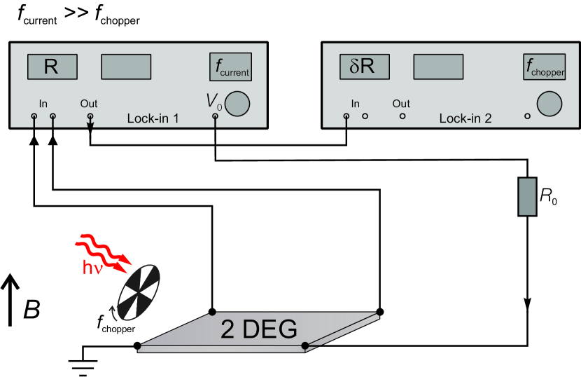
Usually the microwave-induced resistance oscillations (MIRO) are measured under continuous microwave illumination. The photoresponce is thereby obtained by comparing the magnetic field dependencies and of the longitudinal resistance in the presence and absence of radiation. But at low radiation power the amplitude of MIRO becomes small, and this approach is not optimal. Moreover, in our setup the transmittance of radiation is measured using a mechanical chopper such that the incoming radiation is modulated at frequency . Therefore, we measure photoresistance using a double modulation technique specified below.
In our measurements, see Fig. S7 (a), the chopper frequency Hz and a small bias current A is applied to the sample at much higher frequency Hz. The photoresistance is collected as a part of the signal that is modulated at both frequencies: the first lock-in collects the total signal at higher frequency , while its output is fed to the input of the second lock-in tuned to the lower frequency . The output signal of the second lock-in gives the value of .
The comparison of the direct measurements of and using of the double modulation technique is shown in Fig. S7 (b) and (c). It is seen that both methods coincide rather well.
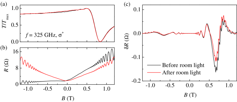
S8 Transmittance, longitudinal resistance, and MIRO before and after room light illumination of the sample
S9 Technological design of the studied 2DES