Nonequilibrium Josephson diode effect in periodically driven SNS junctions
Abstract
In typical Josephson junctions, the Josephson current is an odd function of the superconducting phase difference. Recently, diode effect in Josephson junctions is observed in experiments wherein the maximum and the minimum values of the Josephson current in the current-phase relation do not have the same magnitude. We propose a superconductor-normal metal-superconductor (SNS) junction where Josephson diode effect manifests when the normal metal region is driven. Time reversal symmetry and inversion symmetry need to be broken in the SNS junction for the diode effect to show up. We calculate long time averaged current and show that the system exhibits diode effect for two configurations of the driven SNS junction - one in which inversion symmetry is broken in the undriven part of the Hamiltonian and the other wherein both the symmetries are broken by the driving potential. In the latter configuration, a nonzero current known as anomalous current appears at the junction in absence of phase bias. In the proposed setup, the diode effect vanishes in the adiabatic limit.
I Introduction
The phenomenon of rectification, wherein the two terminal resistance across an electrical device depends on the direction of current, dates back to 1874 Braun (1875). Semiconductor diodes that exhibit this phenomenon consist of a pn-junction and the reason behind rectification is rooted in the fact that the widths of the depletion region in the forward and reverse bias are different Malvino and Bates (2007). However, such a non-reciprocal transport, also known as diode effect, is a purely classical effect in semiconductor diodes. When the transport is quantum coherent, the scattering matrix is unitary and the rectification is not possible in a two terminal setup with normal metal leads Imry (2002). In scattering across interacting regions that break inversion symmetry, though the two-particle scatterings are direction dependent, it does not lead to rectification in current-voltage characteristics Roy et al. (2009). Decoherence in quantum devices can lead to rectification Bredol et al. (2021). It may be noted that in certain devices, the four probe resistance exhibits non-reciprocal quantum coherent transport Song et al. (1998); Ideue et al. (2017); Legg et al. (2022).
The current-voltage characteristics of a superconductor is accompanied by a critical current, below which the voltage drop is zero. In the context of superconductors, the magnitude of critical current through the superconductor being direction dependent marks diode effect. In recent years, the diode effect was observed in superconductors under an applied magnetic field Wakatsuki et al. (2017); Qin et al. (2017); Sivakov et al. (2018); Lustikova et al. (2018); Hoshino et al. (2018); Yasuda et al. (2019); Ando et al. (2020); Itahashi et al. (2020); Baumgartner et al. (2022); Hou et al. (2022); Suri et al. (2022). Time reversal symmetry and inversion symmetry need to be broken to realize the diode effect in superconductors. While in some of these works Wakatsuki et al. (2017); Hoshino et al. (2018); Yasuda et al. (2019); Ando et al. (2020); Itahashi et al. (2020); Baumgartner et al. (2022), the magnetic field in combination with spin-orbit coupling gives rise to magnetochiral anisotropy, vortex dynamics is responsible for the observed diode effect in a few other works Lustikova et al. (2018); Sivakov et al. (2018). Across a junction between two superconductors differing by a phase, a current that depends on the phase difference flows -an effect known as Josephson effect Josephson, B. D. (1962); Anderson and Rowell (1963); Furusaki (1999). The maximum and minimum values of the current as the phase difference is varied are known as critical currents in forward and backward directions. In an inversion symmetry broken Josephson junction setup, the Josephson critical currents in the forward and backward directions are found to be different in magnitude without a need for magnetic field and the origin of the diode effect is debated Wu et al. (2022). An interferometric setup has been proposed wherein a magnetic flux threaded between two channels that connect phase biased superconductors can give rise to Josephson diode effect with efficiencies as large as 40% Souto et al. (2022).
Periodically driven systems have been studied with a renewed interest in recent years, since novel phases of matter can be realized in such out of equilibrium systems Oka and Kitamura (2019); Bandyopadhyay et al. (2021). Tight binding model has been used to study a variety of transport phenomena in periodically driven systems Gómez-León and Platero (2013); Longhi (2017); Mei et al. (2021). Rectification and anomalous current in junctions between Floquet superconductors has also been investigated Soori (2023). Quantum charge pumping is a phenomenon wherein a small region connected to normal metal leads is driven periodically, giving rise to a net flow of charge in the absence of a potential difference Thouless (1983); Brouwer (1998); Switkes et al. (1999); Brouwer (2001); Avron et al. (2001); Moskalets and Büttiker (2002); Agarwal and Sen (2007a, b); Soori and Sen (2010). Quantum charge pumping across regions connected to superconducting leads is investigated by some groups Blaauboer (2002); Governale et al. (2005); Soori and Sivakumar (2020). In a phase biased superconductor-normal metal-superconductor (SNS) junctions, driving the normal metal (NM) region can block the Josephson current and transfer a net charge from one superconductor to another in the absence of a superconducting phase difference Soori and Sivakumar (2020). The net current averaged over a long time quantifies the current flow. We show that in such an SNS junction, by driving the NM region, the Josephson critical currents in the forward and backward directions can be made different in magnitude in two ways. In one way, the inversion symmetry is broken in the undriven Hamiltonian and the long time averaged current is zero when the phases of the two superconductors are the same. In the second way, the undriven system is inversion symmetric and the time dependent potentials in NM region break inversion and time reversal symmetries, wherein a nonzero long time averaged current appears at zero superconducting phase difference.
II Model and calculation
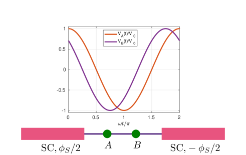
We describe the system with the help of a tight binding model. Superconductors (SCs) have sites and the NM has just two sites. The superconducting phase of the left (right) SC is (). The superconductor on the left (right) is connected to the NM by hopping strength (). Sinusoidal time dependent potentials are applied to the NM sites respectively. and . The oscillating potentials are switched on at . The Hamiltonian for the system is , where for and zero at other times and
| (1) |
, where creates an electron at site with spin and are the Pauli matrices that act on the particle-hole sector. Here, is the hopping amplitude, is the chemical potential, is the magnitude of pairing in the superconducting lattices, is the superconducting phase difference, is the number of sites in each of the finite superconducting lattices, () is the hopping strength for the bond that connects the left (right) superconductor to the central NM region, is the chemical potential in the NM region, is the hopping strength on the bond that connects two sites in the NM region, and are the time dependent onsite potentials on the two sites of the NM region. Fig. 1 shows a schematic picture of the setup. Inversion operator takes , , . Time reversal operator is , where does complex conjugation and is Pauli spin matrix acting on the spin space. Under time reversal, the superconducting phase changes to . It has to be noted that when the system is said to be invariant under time reversal or inversion, it refers to the invariance of the system for the case . The system described by is invariant under inversion when .
First, let us consider the time independent part of the Hamiltonian. A nonzero phase difference in drives a Josephson current at the junction. The Josephson current is the sum of currents carried by all eigenstates of with eigenenergies below zero. Let where be the eigenstates and eigenenergies of such that for all . The current operator at the bond is
| (2) |
where is the electron charge. The Josephson current in the system described by is . The states can be calculated numerically exactly.
The Hamiltonian for . At time , the system described by Hamiltonian moves away from the equilibrium ground state of . The current at the junction for is aperiodic, despite the fact that the Hamiltonian is periodic in time. However, the current is a sum of two parts: one periodic in time and another aperiodic. The aperiodic part vanishes when time averaged over the range and the periodic part survives averaging Soori and Sen (2010). Such a long time averaged current is of central interest in this work, and we sketch the method to calculate . Since the current draws contribution from periodic in time part only and this has a period , the long time averaged current can be calculated by averaging the current over the time interval . If is the period of the time dependent part of the Hamiltonian, the interval is sliced into equal intervals of size . The time dependent Hamiltonian is approximated by a constant Hamiltonian within each of these smaller intervals. If is at the middle of the -th interval, the operator that relates the state of the system at to the state of the system at time is given by
| (3) |
where is time ordering operator. The eigenstates of : have eigenvalues and are termed Floquet states. The operator and their eigenstates can be calculated exactly numerically since ’s are known. For non-degenerate set of eigenstates within a spin subspace, the time averaged current can be expressed as
| (4) | |||||
Eq. (4) points us to the fact that the Floquet states carry the current. The overlap of the initially occupied states with the Floquet eigenstate dictates the weight of each Floquet state to the long time averaged current. In eq. (4), is the current carried by the Floquet state in the time interval of size centered at . The current can be calculated numerically exactly. The Floquet states are nonequilibrium states, and hence the diode effect exhibited by in the driven system is a nonequilibrium effect.
III Results and Analysis
Certain effects of driving in Josephson junctions have been studied in detail in a closely related model Soori and Sivakumar (2020). Our focus in this work will be to study Josephson diode effect by analyzing the current phase relation, where current refers to the long time averaged current .
Josephson critical current in the forward (backward) direction () is defined as the maximum (minimum) value of the current in the current phase relation. Typically, and . Diode effect is characterized by and is quantified by diode effect coefficient, defined as . A nonzero value of indicates the diode effect. The system does not exhibit diode effect if it is invariant under inversion or time-reversal.
III.1
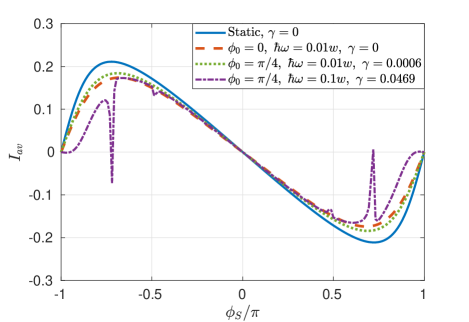
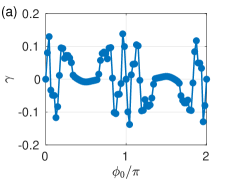
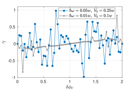
In this subsection, we study diode effect by breaking inversion symmetry of by choosing . We investigate the current phase relation for -the case when there is no pumping in the absence of a superconducting phase difference between the two superconductors. The dispersion in the superconductors is , and the Josephson current is carried by subgap states that decay into the superconductor. For a state with , the decay length is close to for , . Hence, a superconductor with sites mimics a sufficiently long superconductor and we choose , , . Current phase relations for , , , , , , , and are shown in Fig. 2. The values of and for each curve are indicated in the legend. is chosen to be to break the degeneracy of eigenstates. We find that for the diode effect is absent even in inversion asymmetric system since the system is invariant under time-reversal. For , we find that the long time averaged current at a phase difference satisfies . In Fig. 2, the diode effect coefficient is indicated for each curve. This explains why the diode effect is absent for for . But for the choice , the system exhibits diode effect.
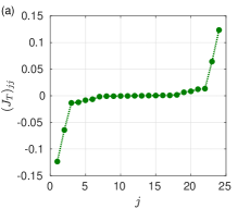
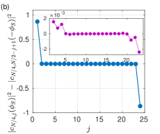
The net Josephson current is carried by the Floquet states. To explain the results obtained, we analyze the current carried by a Floquet state at different times in a time period for two values of the superconducting phase differences: . For the case of , the periodic part of the current at time for a superconducting phase difference satisfies . The reason for this is that the ground state of the undriven system at superconducting phase differences and are related by time reversal operation. Time evolution over a time and are effectively time evolutions in opposite directions of time by the same duration since , under the Hamiltonian . Further, the Hamiltonians at times and are exactly the same. However, for the case , the Hamiltonians at times and are not the same. In this case, the current at time for is not equal to the magnitude of current for at any other time in the time interval . This makes the time averaged currents for and have different magnitudes and leads to diode effect. There is another way to understand the diode effect. The ordered (in ascending order) sets of average currents carried by the Floquet states for the SC phase differences and are the same. Further, the Floquet states come in pairs that carry time averaged currents which are equal in magnitude and opposite in sign. Fig. 3(a) shows the time averaged currents carried by the Floquet states for . For , the set of weights for the choice of SC phase differences satisfies: . Here, we make use of the fact that the system is spin degenerate - up spin electron pairs with down spin hole and down spin electron pairs with up spin hole. So, we restrict the Hamiltonian to only the sector which has up spin electrons and down spin holes making the Hamiltonian an matrix. Hence, the time averaged currents for phase differences and are equal in magnitude and opposite in sign for . But, for , the set of weights do not satisfy . This leads to the time averaged current not being an odd function of , finally resulting in diode effect. Fig. 3(b) shows the weights for and it is evident from the figure that weights do not satisfy: . The time averaged currents carried by the initial state for are respectively . Fig. 4(a) shows the dependence of the diode effect coefficient on . We can see that the diode effect is absent for .
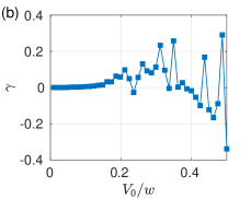
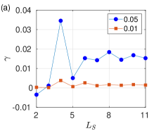
Next, we examine the dependence of the diode effect coefficient on for keeping other parameters the same. The diode effect coefficient is plotted as a function of in Fig. 4(b). The diode effect coefficient grows in magnitude as is gradually increased from and then oscillates with a large magnitude, even changing its sign. This is because, the minimum value of the difference between the energy levels of the undriven system close to zero energy is for the chosen value of parameters. When is larger than this value, the time dependent potential mixes the energy levels significantly and results in a large magnitude of the diode effect coefficient. As increases further from , the mixing of the energy levels of the undriven system is affected substantially, leading to oscillation in the value of the diode effect coefficient.
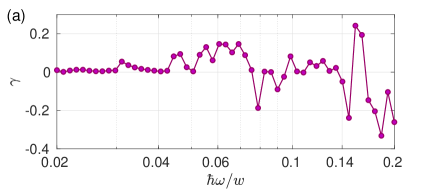
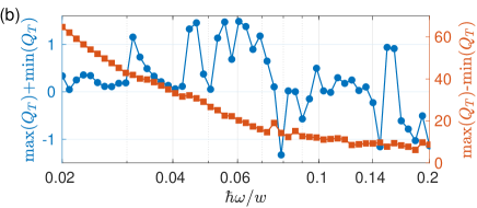
Now, we study - ‘how does the change in frequency of the periodic potential affect diode effect?’ In the numerical calculation, the time interval over which the current is averaged is sliced into small intervals and in each of these intervals of duration , the time dependent potentials are treated as constants. Hence, while studying the dependence of the diode effect coefficient as a function of , we keep the duration almost the same as the frequency of the periodic potential is varied. We show the dependence of diode effect coefficient on frequency in Fig. 5(a) for , keeping other parameters the same. We choose , where corresponds to the largest integer less that . It can be seen that the diode effect coefficient approaches zero in the adiabatic limit. In the adiabatic limit, charge transferred across the two electrodes over one time period is calculated. To comprehend the dependence of the diode effect coefficient in the adiabatic limit, the sum and difference are plotted as functions of the frequency in Fig. 5(b). The diode effect coefficient is related to by . It can be seen that though the maximum charge transferred in one time period between the phase biased superconductors diverges as , the difference between the magnitudes of the maximum charge transferred in the forward and backward directions remains almost the same in magnitude as making the diode effect coefficient approach zero in the adiabatic limit.
III.2 breaks inversion and time reversal symmetries
In this subsection, we study the case in which the time-independent part of the Hamiltonian is inversion symmetric, but the inversion and time reversal symmetries are broken by the time dependent part of the Hamiltonian. In such a case, the diode effect is absent for since there is no preferential direction in which the current is favored. The ordered sets of time averaged currents carried by the Floquet states for the superconducting phases differences are not the same in this case in contrast to the first method wherein . However, for , a nonzero current is pumped even at and the time dependent potentials break inversion and time reversal symmetry. This gives a preferential direction for the flow of current, and the system exhibits diode effect. In Fig. 6, the diode effect coefficient is plotted as a function of the difference in phases of the time-dependent potentials for , , and . We see that the diode effect coefficient is nonzero for . Further, we find that the diode effect coefficient tends to zero in the adiabatic limit despite a finite amount of charge being transferred from one SC to another over one time period, which can be explained using figures similar to Fig. 5.
III.3 Dependence on
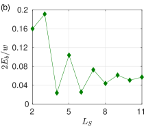
In our calculations so far, we have taken . In this section, we analyze the dependence of the diode effect on -the size of the superconductor. For small driving frequencies, eigenstates close to zero energy participate in the dynamics. For energies within the superconducting gap, the wave function in the superconductor decays away from the junction and for zero energy state, the wave function diminishes by a factor over a length for the choice of parameters used in the paper. In Fig. 7(a), we plot the diode effect coefficient versus the length of the SC region. In Fig. 7(b), the dependence of - the minimum value of the difference between energy levels of closest to zero as is varied is plotted versus the size of the superconductor. It is evident that the diode effect coefficient is peaked at and saturates as increases. This is because, for smaller values of , the charge driven from one SC to another reflects back from the boundary of the second SC and returns back to the first SC. As the becomes larger, the driven charge relaxes in the second SC. Also, depends on and comparing subplots (a) and (b) in Fig. 7, one can infer that for smaller values of the energy difference , driving results in higher value of . For , the driving makes transition between energy levels of closest to zero possible, whereas for , driving can help transition between energy levels of closest to zero only through a higher order processes Moskalets and Büttiker (2002). The energy difference for larger length is much closer to the driving frequency for and results in much higher values of .
IV Summary and Conclusion
We have proposed a setup where Josephson diode effect can be realized by periodic driving of the NM region in an SNS junction. Time reversal and inversion symmetries need to be broken for the diode effect to show up. There are two ways in which diode effect can be accomplished in the system: one by breaking inversion symmetry in the undriven part of the Hamiltonian by choosing and another by breaking symmetries purely in the driven part of the Hamiltonian by choosing . Naturally, a combination of the two ways wherein both and can also result in diode effect. We have studied the dependence of the diode effect coefficient on the amplitude of the driving potential and frequency . We find that though the charge may be pumped in the adiabatic limit, the diode effect vanishes in the adiabatic limit in both the schemes. The setup in this work that exhibits diode effect is a two terminal setup, in contrast to many four terminal setups Song et al. (1998); Ideue et al. (2017); Sivakov et al. (2018); Ando et al. (2020); Legg et al. (2022); Hou et al. (2022).
In a realistic setup, it is possible that the periodic driving heats up the system and the low temperature environment cools the system. This effect is not captured by the formalism here. Also, such a process takes much longer times compared to the time scale of driving and it is unlikely that it hinders the experimental realization of the proposed phenomenon.
Recently, Josephson junction with graphene in the middle driven with the help of microwave irradiation has been experimentally realised Park et al. (2022). The ability to periodically modulate the potential in quantum dots connected to superconductors Cleuziou et al. (2006); De Franceschi et al. (2010); Wan et al. (2015) forms an important step in experimentally realizing the proposed setup. Purely metallic systems driven by periodic potentials that exhibit pumping have been realized experimentally Switkes et al. (1999); Drexler et al. (2013). Hence, the setup proposed is within the reach of present technology. Josephson junctions promise development of quantum computer Clarke and Wilhelm (2008); Devoret and Schoelkopf (2013) and have influenced quantum technologies Kleiner (2007); Lee et al. (2020). Also, Josephson junctions have been proposed to be platforms in braiding of non-Abelian Majorana fermions van Heck et al. (2012). Hence, realization of nonequilibrium Josephson diodes proposed in this work will add to an assortment of quantum devices that will shape the future research.
While revising the manuscript, we became aware of ref. Ortega-Taberner et al. (2023) where rectification and anomalous Josephson current have been studied in a setup similar to ours.
Acknowledgements
The author thanks Udit Khanna and Diptiman Sen for useful discussions. The author thanks Dhavala Suri for bringing his attention to the phenomenon of superconducting diode effect and discussions. The author acknowledges financial support by DST through DST-INSPIRE Faculty Award (Faculty Reg. No. : IFA17-PH190).
References
- Braun (1875) F. Braun, “Ueber die stromleitung durch schwefelmetalle,” Annalen der Physik 229, 556–563 (1875).
- Malvino and Bates (2007) A. Malvino and D. J. Bates, Electronic Principles (McGraw-Hill Higher Education, 2007).
- Imry (2002) Y. Imry, Introduction to Mesoscopic Physics (Oxford University Press, Oxford, 2002).
- Roy et al. (2009) D. Roy, A. Soori, D. Sen, and A. Dhar, “Nonequilibrium charge transport in an interacting open system: Two-particle resonance and current asymmetry,” Phys. Rev. B 80, 075302 (2009).
- Bredol et al. (2021) P. Bredol, H. Boschker, D. Braak, and J. Mannhart, “Decoherence effects break reciprocity in matter transport,” Phys. Rev. B 104, 115413 (2021).
- Song et al. (1998) A. M. Song, A. Lorke, A. Kriele, J. P. Kotthaus, W. Wegscheider, and M. Bichler, “Nonlinear electron transport in an asymmetric microjunction: A ballistic rectifier,” Phys. Rev. Lett. 80, 3831–3834 (1998).
- Ideue et al. (2017) T. Ideue, K. Hamamoto, S. Koshikawa, M. Ezawa, S. Shimizu, Y. Kaneko, Y. Tokura, N. Nagaosa, and Y. Iwasa, “Bulk rectification effect in a polar semiconductor,” Nature Physics 13, 578–583 (2017).
- Legg et al. (2022) H. F. Legg, M. Rößler, F. Münning, D. Fan, O. Breunig, A. Bliesener, G. Lippertz, A. Uday, A. A. Taskin, D. Loss, J. Klinovaja, and Y. Ando, “Giant magnetochiral anisotropy from quantum-confined surface states of topological insulator nanowires,” Nature Nanotechnology 17, 696–700 (2022).
- Wakatsuki et al. (2017) R. Wakatsuki, Y. Saito, S. Hoshino, Y. M. Itahashi, T. Ideue, M. Ezawa, Y. Iwasa, and N. Nagaosa, “Nonreciprocal charge transport in noncentrosymmetric superconductors,” Science Advances 3, e1602390 (2017).
- Qin et al. (2017) F. Qin, W. Shi, T. Ideue, M. Yoshida, A. Zak, R. Tenne, T. Kikitsu, D. Inoue, D. Hashizume, and Y. Iwasa, “Superconductivity in a chiral nanotube,” Nature Communications 8, 14465 (2017).
- Sivakov et al. (2018) A. G. Sivakov, O. G. Turutanov, A. E. Kolinko, and A. S. Pokhila, “Spatial characterization of the edge barrier in wide superconducting films,” Low Temperature Physics 44, 226–232 (2018).
- Lustikova et al. (2018) J. Lustikova, Y. Shiomi, N. Yokoi, N. Kabeya, N. Kimura, K. Ienaga, S. Kaneko, S. Okuma, S. Takahashi, and E. Saitoh, “Vortex rectenna powered by environmental fluctuations,” Nature Communications 9, 4922 (2018).
- Hoshino et al. (2018) S. Hoshino, R. Wakatsuki, K. Hamamoto, and N. Nagaosa, “Nonreciprocal charge transport in two-dimensional noncentrosymmetric superconductors,” Phys. Rev. B 98, 054510 (2018).
- Yasuda et al. (2019) K. Yasuda, H. Yasuda, T. Liang, R. Yoshimi, A. Tsukazaki, K. S. Takahashi, N. Nagaosa, M. Kawasaki, and Y. Tokura, “Nonreciprocal charge transport at topological insulator/superconductor interface,” Nature Communications 10, 2734 (2019).
- Ando et al. (2020) F. Ando, Y. Miyasaka, T. Li, J. Ishizuka, T. Arakawa, Y. Shiota, T. Moriyama, Y. Yanase, and T. Ono, “Observation of superconducting diode effect,” Nature 584, 373–376 (2020).
- Itahashi et al. (2020) Y. M. Itahashi, T. Ideue, Y. Saito, S. Shimizu, T. Ouchi, T. Nojima, and Y. Iwasa, “Nonreciprocal transport in gate-induced polar superconductor SrTiO3,” Science Advances 6, eaay9120 (2020).
- Baumgartner et al. (2022) C. Baumgartner, L. Fuchs, A. Costa, S. Reinhardt, S. Gronin, G. C. Gardner, T. Lindemann, M. J. Manfra, P. E. Faria Junior, D. Kochan, J. Fabian, N. Paradiso, and C. Strunk, “Supercurrent rectification and magnetochiral effects in symmetric Josephson junctions,” Nature Nanotechnology 17, 39–44 (2022).
- Hou et al. (2022) Y. Hou, F. Nichele, H. Chi, A. Lodesani, Y. Wu, M. F. Ritter, D. Z. Haxell, M. Davydova, S. Ilic, F. S. Bergeret, A. Kamra, L. Fu, P. A. Lee, and J. S. Moodera, “Ubiquitous superconducting diode effect in superconductor thin films,” arXiv:2205.09276 (2022).
- Suri et al. (2022) D. Suri, A. Kamra, T. N. G. Meier, M. Kronseder, W. Belzig, C. H. Back, and C. Strunk, “Non-reciprocity of vortex-limited critical current in conventional superconducting micro-bridges,” Appl. Phys. Lett. 121, 102601 (2022).
- Josephson, B. D. (1962) Josephson, B. D., “Possible new effects in superconductive tunnelling,” Phys. Lett. 1, 251 (1962).
- Anderson and Rowell (1963) P. W. Anderson and J. M. Rowell, “Probable observation of the Josephson superconducting tunneling effect,” Phys. Rev. Lett. 10, 230–232 (1963).
- Furusaki (1999) A. Furusaki, “Josephson current carried by Andreev levels in superconducting quantum point contacts,” Superlattices and Microstructures 25, 809–818 (1999).
- Wu et al. (2022) H. Wu, Y. Wang, Y. Xu, P. K. Sivakumar, C. Pasco, U. Filippozzi, S. S. P. Parkin, Y.-J. Zeng, T. McQueen, and M. N. Ali, “The field-free Josephson diode in a van der Waals heterostructure,” Nature 604, 653–656 (2022).
- Souto et al. (2022) R. S. Souto, M. Leijnse, and C. Schrade, “Josephson diode effect in supercurrent interferometers,” Phys. Rev. Lett. 129, 267702 (2022).
- Oka and Kitamura (2019) T. Oka and S. Kitamura, “Floquet engineering of quantum materials,” Annual Review of Condensed Matter Physics 10, 387–408 (2019).
- Bandyopadhyay et al. (2021) S. Bandyopadhyay, S. Bhattacharjee, and D. Sen, “Driven quantum many-body systems and out-of-equilibrium topology,” J. Phys.: Condens. Matter 33, 393001 (2021).
- Gómez-León and Platero (2013) A. Gómez-León and G. Platero, “Floquet-bloch theory and topology in periodically driven lattices,” Phys. Rev. Lett. 110, 200403 (2013).
- Longhi (2017) S. Longhi, “Non-Hermitian Floquet invisibility,” EPL 117, 10005 (2017).
- Mei et al. (2021) Jie Mei, Xiyin Ye, Hengyi Xu, Xiaoming Zhu, and Ning Xu, “Floquet anomalous Hall effect in ferromagnetic multiorbital tight-binding models,” J. Phys.: Condens. Matter 34, 015304 (2021).
- Soori (2023) A. Soori, “Anomalous Josephson effect and rectification in junctions between Floquet topological superconductors,” Physica E 146, 115545 (2023).
- Thouless (1983) D. J. Thouless, “Quantization of particle transport,” Phys. Rev. B 27, 6083–6087 (1983).
- Brouwer (1998) P. W. Brouwer, “Scattering approach to parametric pumping,” Phys. Rev. B 58, R10135–R10138 (1998).
- Switkes et al. (1999) M. Switkes, C. M. Marcus, K. Campman, and A. C. Gossard, “An adiabatic quantum electron pump,” Science 283, 1905–1908 (1999).
- Brouwer (2001) P. W. Brouwer, “Rectification of displacement currents in an adiabatic electron pump,” Phys. Rev. B 63, 121303 (2001).
- Avron et al. (2001) J. E. Avron, A. Elgart, G. M. Graf, and L. Sadun, “Optimal quantum pumps,” Phys. Rev. Lett. 87, 236601 (2001).
- Moskalets and Büttiker (2002) M. Moskalets and M. Büttiker, “Floquet scattering theory of quantum pumps,” Phys. Rev. B 66, 205320 (2002).
- Agarwal and Sen (2007a) A. Agarwal and D. Sen, “Equation of motion approach to non-adiabatic quantum charge pumping,” J. Phys.: Condens. Matter 19, 046205 (2007a).
- Agarwal and Sen (2007b) A. Agarwal and D. Sen, “Nonadiabatic charge pumping in a one-dimensional system of noninteracting electrons by an oscillating potential,” Phys. Rev. B 76, 235316 (2007b).
- Soori and Sen (2010) A. Soori and D. Sen, “Nonadiabatic charge pumping by oscillating potentials in one dimension: Results for infinite system and finite ring,” Phys. Rev. B 82, 115432 (2010).
- Blaauboer (2002) M. Blaauboer, “Charge pumping in mesoscopic systems coupled to a superconducting lead,” Phys. Rev. B 65, 235318 (2002).
- Governale et al. (2005) M. Governale, F. Taddei, R. Fazio, and F. W. J. Hekking, “Adiabatic pumping in a superconductor-normal-superconductor weak link,” Phys. Rev. Lett. 95, 256801 (2005).
- Soori and Sivakumar (2020) A. Soori and M. Sivakumar, “Nonadiabatic charge pumping across two superconductors connected through a normal metal region by periodically driven potentials,” J. Phys.: Condens. Matter 32, 365304 (2020).
- Park et al. (2022) S. Park, W. Lee, S. Jang, Y.-B. Choi, J. Park, W. Jung, K. Watanabe, T. Taniguchi, G. Y. Cho, and G.-H. Lee, “Steady Floquet–Andreev states in graphene Josephson junctions,” Nature 603, 421–426 (2022).
- Cleuziou et al. (2006) J.-P. Cleuziou, W. Wernsdorfer, V. Bouchiat, T. Ondarçuhu, and M. Monthioux, “Carbon nanotube superconducting quantum interference device,” Nature Nanotechnology 1, 53–59 (2006).
- De Franceschi et al. (2010) S. De Franceschi, L. Kouwenhoven, C. Schönenberger, and W. Wernsdorfer, “Hybrid superconductor–quantum dot devices,” Nature Nanotechnology 5, 703–711 (2010).
- Wan et al. (2015) Z. Wan, A. Kazakov, M. J. Manfra, L. N. Pfeiffer, K. W. West, and L. P. Rokhinson, “Induced superconductivity in high-mobility two-dimensional electron gas in gallium arsenide heterostructures,” Nature Communications 6, 7426 (2015).
- Drexler et al. (2013) C. Drexler, S. A. Tarasenko, P. Olbrich, J. Karch, M. Hirmer, F. Müller, M. Gmitra, J. Fabian, R. Yakimova, S. Lara-Avila, S. Kubatkin, M. Wang, R. Vajtai, P. M. Ajayan, J. Kono, and S. D. Ganichev, “Magnetic quantum ratchet effect in graphene,” Nature Nanotechnology 8, 104–107 (2013).
- Clarke and Wilhelm (2008) J. Clarke and F. K. Wilhelm, “Superconducting quantum bits,” Nature 453, 1031–1042 (2008).
- Devoret and Schoelkopf (2013) M. H. Devoret and R. J. Schoelkopf, “Superconducting circuits for quantum information: An outlook,” Science 339, 1169–1174 (2013).
- Kleiner (2007) R. Kleiner, “Filling the terahertz gap,” Science 318, 1254–1255 (2007).
- Lee et al. (2020) G-H. Lee, D. K. Efetov, W. Jung, L. Ranzani, E. D. Walsh, T. A. Ohki, T. Taniguchi, K. Watanabe, P. Kim, D. Englund, and K. C. Fong, “Graphene-based Josephson junction microwave bolometer,” Nature 586, 42–46 (2020).
- van Heck et al. (2012) B van Heck, A R Akhmerov, F Hassler, M Burrello, and C W J Beenakker, “Coulomb-assisted braiding of Majorana fermions in a Josephson junction array,” New Journal of Physics 14, 035019 (2012).
- Ortega-Taberner et al. (2023) C. Ortega-Taberner, A-P. Jauho, and J. Paaske, “Anomalous Josephson current through a driven double quantum dot,” Phys. Rev. B 107, 115165 (2023).