Beyond-Cell Communications via HAPS-RIS
††thanks: This research has been supported in part by a scholarship from King AbdulAziz
University, Saudi Arabia, and in part by
Huawei Canada Company Ltd.
Abstract
The ever-increasing number of users and new services in urban regions can lead terrestrial base stations (BSs) to become overloaded and, consequently, some users to go unserved. Compounding this, users in urban areas can face severe shadowing and blockages, which means that some users do not receive a desired quality-of-service (QoS). Motivated by the energy and cost benefits of reconfigurable intelligent surfaces (RIS) and the advantages of high altitude platform station (HAPS) systems, including their wide footprint and strong line-of-sight (LoS) links, we propose a solution to support the stranded users using the RIS-aided HAPS. Particularly, we propose to support the stranded users by a dedicated control station (CS) via a HAPS equipped with RIS (HAPS-RIS). Through this approach, users are not restricted from being supported by the cell they belong to; hence, we refer to this approach as beyond-cell communication. As we demonstrate in this paper, beyond-cell communication works in tandem with legacy terrestrial networks to support uncovered or unserved users. Optimal transmit power and RIS unit assignment strategies for the users based on different network objectives are introduced. Numerical results demonstrate the benefits of the proposed beyond-cell communication approach. Moreover, the results provide insights into the different optimization objectives and their interplay with minimum QoS and network resources, such as transmit power and the number of RIS reflecting units.
I Introduction
One of the main goals of future wireless network is to provide ubiquitous connectivity (i.e., wireless connectivity to everyone and everything, everywhere, every time at an affordable rate) [1]. Ubiquitous connectivity can be achieved in urban areas through the dense deployment of base stations (BSs), including small cells. However, with increasing numbers of users and hampered by severe shadowing, blockages, and non-line-of-sight (NLoS) links, even ultra dense networks cannot support all users in an urban area. Further, deploying a large number of BSs inevitably leads to high capital expenditures (CAPEX) and operational expenditures (OPEX) [2].
Recent studies have proposed deploying reconfigurable intelligent surfaces (RIS) around BSs as an energy-efficient solution to overcome severe shadowing and blockage effects [3]. An RIS is a reflecting surface built from a massive number of tiny reflecting units [4, 5, 6]. Each reflecting unit is controllable, and thus it can focus the impinging signals in a desired direction in a nearly passive way. Thus, RIS are energy-efficient alternative to active antenna architecture such as relays [4, 5]. However, the deployment of RIS in terrestrial networks involves several challenges, including inflexible deployment and weak wireless channel conditions due to shadowing, blockages and NLoS links. In addition, dynamic and unpredictable network traffic generates unprecedented data rate demands, which can overload some BSs. Accordingly, even an optimized deployment of BSs and RIS in urban areas might be unable to cope with the dynamic demands.
To overcome these issues, we recently proposed integrating RIS with non-terrestrial networks (NTN) in previous works [4, 7]. Due to the limited energy on aerial platforms, integrating RIS with NTN is more appealing than integrating them in terrestrial networks. In these works, we also discussed several benefits of RIS-aided NTN, including energy and cost savings, favorable wireless channel conditions, strong LoS links, a wider coverage area, and flexible placement. In another work [8], we also provided a detailed link budget analysis of different RIS-aided aerial platforms, such as unmanned aerial vehicles (UAVs), high altitude platform station (HAPS) nodes, and low Earth orbit (LEO) satellites, and we compared that to RIS-aided terrestrial networks.
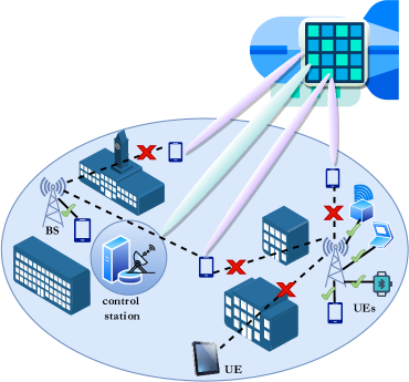
As we also showed in [8], the typical large size of a HAPS allows the accommodation of a large number of reflecting units. Thus, it can outperform other aerial RIS-aided systems, such as UAV-RIS. Therefore, motivated by the aforementioned findings, we propose in this paper a novel beyond-cell communications approach involving an HAPS equipped with RIS (HAPS-RIS). This approach works in tandem with legacy terrestrial networks by offering service to unsupported users whose quality-of-service (QoS) requirements cannot be fulfilled by legacy networks. In our proposed scheme, unsupported users are connected to a dedicated control station (CS) via a HAPS-RIS. The main contributions in this paper include, but are not limited to, the following:
-
•
We formulate three novel optimization problems, including throughput maximization, worst user rate maximization, and reflecting units usage minimization to design optimal power and RIS unit assignment strategies for the users supported through beyond-cell communications.
-
•
We present thorough numerical simulation results, which indicate that beyond-cell communications complement legacy terrestrial networks well and enhance the total number of users served. The percentage of users that satisfy the QoS requirements increases while the required number of terrestrial BSs decreases.
-
•
We also provide important insights about the different allocation schemes. By conceding a small degradation (1%) in the system sum rate, the worst user rate maximization-based allocation scheme maximizes the fairness among the users and increases the rate of the worst user (15%). Moreover, by increasing the CS power by 1 dB, the size of the HAPS or the required number of reflectors is decreased by 11%.
The remainder of the paper is organized as follows. Section II presents the system model for all user equipment (UE), whether connected to a BS or supported by a HAPS-RIS. Section III details the problem formulations for different system objectives. The proposed solutions are discussed in Section IV, while the numerical results are presented and discussed in Section V. Finally, Section VI concludes the paper.
II System Model
We consider a downlink transmission scenario in an integrated terrestrial and non-terrestrial wireless network consisting of a single HAPS with a coverage area that includes base stations (BSs) and single-antenna UEs (e.g., smart phones, sensing nodes or Internet-of-Things devices, etc.). The HAPS is located in the center of the coverage area at an altitude of 20 km111Generally, HAPS systems are quasi-stationary [3], and hence, their mobility is ignored in this model., and it is equipped with the RIS with a total of reflecting units. Since the antennas of BSs are down-tilted to serve terrestrial UEs, we consider the HAPS coverage area also includes a dedicated high-directional antenna gain transceiver, known as the ground CS. The CS is connected to the core network with the primary aim of supporting unserved UEs via the HAPS-RIS. Further, the CS also manages the association between the BSs and the UEs and configures the RIS.
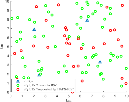
The environment for this scenario is an urban one where UEs are uniformly distributed in the HAPS coverage area. In contrast, the BSs are optimally placed to maximize the number of connected UEs. We adopt Lloyd’s algorithm for optimizing the placement of BSs. The algorithm aims to minimize the Euclidean distances between the UEs and the BSs; this distance is the factor that most affects the quality of the channel links222This algorithm is also known as a -means clustering algorithm [9].. In an urban environment, wireless signals suffer severe blockages and shadowing [10]. Accordingly, some UEs might not be associated with any BSs due to poor channel quality. Moreover, some UEs might not have service when BSs are fully loaded. Thus, the UEs in the system can be divided into two groups. The first group includes the UEs that can be served by BSs; the second group consists of the remaining UEs that can be served by the CS via HAPS-RIS.
II-A Within-Cell Connection: UEs to Terrestrial BSs
In this work, we employ the orthogonal frequency division multiplexing (OFDM) transmission scheme, where the entire terrestrial system bandwidth Hz is divided into equal subcarriers each of bandwidth Hz. Without loss of generality, the UEs in each cell are allowed to use only one subcarrier to transmit their data. However, the UEs from other cells can use the same subcarrier. Thus, there will be inter-cell interference but no intra-cell interference.
Accordingly, the received signal at UE from BS on a given subcarrier can be written as
| (1) |
where and denote the transmitted power and the transmitted symbol, respectively. denotes the additive white Gaussian noise (AWGN) with zero mean and power spectral density . denotes the channel coefficient between UE and BS on a given subcarrier, and it can be expressed as
| (2) |
where and denote the antenna gain of BS and UE , respectively. denotes the path loss of the channel between BS and UE . Now, the achievable signal-to-interference-plus-noise ratio (SINR) at UE served by BS can be written as
| (3) |
The corresponding achievable rate in bits per seconds (bps) between BS and UE can be written as
| (4) |
For a UE to be directly associated with a BS , the data rate between them should be above the minimum required data rate, i.e., . Let denote the set of data rates between UE and BSs that have a data rate higher than the minimum required rate . The UE is associated with the BS with the highest data rate in the set , i.e., (). Also, let denote the set of UEs with the best channel toward BS , and the cardinality of the set is denoted as .
For the UE with (i.e., , ), its communication is supported by the CS through HAPS-RIS. Also, when , we declare the BS as fully loaded or its capacity as fully utilized. Hence, we drop UEs with the lowest channel gain to be served by the CS via HAPS-RIS until . Accordingly, we denote the set of UEs supported by direct links from the BSs (within-cell communications) with . Similarly, we denote the set of UEs supported by the CS through HAPS-RIS (beyond-cell communications) with .
II-B Beyond-Cell Connection: UEs to CS via HAPS-RIS
The unsupported UEs that cannot form a direct connection with the terrestrial BS will be served by the CS via HAPS-RIS. We assume that the CS serves the UEs in set using the OFDM protocol, and hence, there will be no inter-UE interference. Further, both within-cell and beyond-cell communications occur in two orthogonal frequency bands, while keeping same for both types of connection. Consequently, there will be no interference between within-cell UEs belonging to set and beyond-cell UEs belonging to set .
Accordingly, the received signal at UE can be expressed as
| (5) |
where and denote the transmit power and the zero-mean AWGN of UE , respectively. denotes the effective channel gain from the CS to the HAPS-RIS and from the HAPS-RIS to UE , and it is given by [8]333Here, we consider negligible difference in channels between UE and RIS reflecting units, since they are dominated by LoS links.
| (6) |
where denotes the transmit antenna gain of the control station, and is the receiver antenna gain of UE . represents the cascaded path loss between the control station and the HAPS (i.e., ), and between the HAPS and UE (i.e., ). Furtehr, represents the reflection gain of the RIS corresponding to UE , and is expressed as
| (7) |
where denotes the reflection loss corresponding to reflector unit , while and represent the corresponding phases between reflector unit and both the control station and UE , respectively. represents the adjusted phase shift of reflector unit , while represents the total number of reflecting units allocated to UE . The RIS reflecting units are divided among the UEs because each UE uses different subcarrier.
Accordingly, the signal-to-noise ratio (SNR) at UE can be written as
| (8) |
and the achievable rate of UE can be expressed as
| (9) |
III Problem Formulation
In this section, we discuss three resources (available power at the CS and reflecting units at the HAPS) allocation schemes for the UEs assisted by the beyond-cell communication, and accordingly, formulate three optimization problems.
III-A Sum Rate (Throughput) Maximization
The goal of this problem is to support all the UEs and maximize their sum rate by optimally allocating the reflecting units and transmitting power to all the UEs. Thus, the formulation becomes
| s.t. | ||||
where (III-A) limits the number of terrestrial BSs in the area; and thus, limits the expenditure incurred by network operators. Note that, the value of is dependent on the value of . Higher the value of , lower is the value of . Constraint (III-A) ensures that the minimum required rate is achieved by each UE. Constraint (III-A) guarantees that the total number of allocated reflecting units to all UEs is less than the maximum number available at the HAPS. In practice, the value of is dependent on the HAPS size. Constraint (III-A) specifies the discrete range of the adjustable phase shifts for the reflectors, where is dependent on the resolution of the phase shift. Constraint (III-A) ensures the total allocated power for each UE does not exceed the maximum power, , of the control station. Constraints (III-A)-(III-A) ensure feasible and fair allocation of both reflecting units and CS power, respectively, where , , and denote the minimum and maximum allocated RIS units and power per UE.
III-B Minimum Rate Maximization (Max-Min Rate)
Sum rate (throughput) maximization based allocation scheme might be biased toward UEs with better channel links. Therefore, for fair resource allocation, we consider in this subsection the problem of maximizing the minimum rate among all UEs. Accordingly, the max-min fairness problem can be formulated as
| s.t. |
III-C Reflecting Units Minimization
Despite being passive in nature, the RIS reflecting units consume energy for control and configuration [4, 5]. The energy consumption might be significant for HAPS equipped with a large number of reflectors. For a cost-effective deployment of HAPS in terms of on-board energy consumption and size of HAPS, it is essential to minimize the total number of RIS reflecting units. Accordingly, the RIS reflecting units minimization problem can be formulated as
| s.t. |
IV Proposed Solution
In this section, we discuss the solution approaches for the aforementioned optimization problems.
IV-A Sum Rate Maximization
In problem (III-A), constraint (III-A) is determined by an expenditure analysis of the network deployment, and typically it is selected as to maximize the percentage of UEs with direct connections to BSs. It should be noted that the variables and are discrete variables; and thus (III-A) becomes computationally challenging to solve as it requires employing heuristic discrete optimization algorithms. However, for a large RIS area, can be approximated as a continuous variable. This approximation is substantiated by the fact that each UE is allocated a subarea of the RIS, and the total area allocated to all UEs is approximately equivalent to the total RIS area. Similarly, in (III-A) practically has a range of discrete phase shifts. However, several works have shown that close to optimal continuous performance can be achieved even with low resolution discrete phase shifts [11]. Therefore, can be approximated as a continuous variable. Moreover, for large values of the rate of UE , given in (9), can be approximated as Accordingly, the sum rate of the set UEs is given as
| (13) |
Moreover, the rate constraint (III-A) of each UE can be written in terms of its SNR. Accordingly, problem (III-A) can be reformulated as
| s.t. | ||||
IV-B Minimum Rate Maximization (Max-Min Rate)
IV-C Reflecting Units Minimization
Following the same procedure applied in the previous subsection, and by relaxing to be a continuous variable, the problem (III-C) can be re-written as
| s.t. |
It is easy to notice that (IV-C) is also an GP problem and can be solved optimally [12], and the final value of is approximated as .
V Numerical Results and Discussion
In this section, we discuss the performance of the proposed beyond-cell communication approach by comparing different power and RIS-unit allocation strategies obtained by solving the aforementioned problems (i.e., (III-A), (III-B), and (III-C)) and a benchmark proportional scheme. The benchmark scheme allocates the reflectors to each UE proportionally based on its channel gain, i.e., the UE with the worst channel gain will get the largest portion of the reflecting units.
In the simulation setup, we consider an urban environment with an area of 10 km by 10 km consisting of terrestrial BSs serving randomly and uniformly distributed UEs with a minimum separation distance of 100 m between the UEs. The BSs are typically placed where the UE density is expected to be higher. Therefore, the BS locations are optimized using Lloyd’s algorithm, which minimizes the distances between all the UEs and their associated BSs [9]. Further, we adopt the 3GPP standards [10] for terrestrial BS parameters with a BS height of m and a power and antenna gain of dBm and dB. Also, we consider the communication at carrier frequency GHz with shadowing standard deviation dB, and all the UEs have the same height of 1.5 m. Then, by following the urban channel model for the path loss and the LoS probabilities detailed in [10, Tables 7.4.1-1 – 7.4.2-1], the channel gains between all UEs and all BSs are obtained. Unless stated otherwise, we consider Mb/s as the minimum rate for direct connection between a UE and a BS.
Accordingly, a UE will be associated with a BS that provides the highest data rate. Fig. 2 illustrates the optimized locations of BSs among randomly and uniformly distributed UEs. The UEs marked with red circles do not satisfy the minimum rate requirement for any BSs. Therefore, they will be served by the CS through HAPS-RIS. Following the standardized 3GPP channel model established for a HAPS and terrestrial nodes in urban environments [13, Sec. 6], and the scattering reflecting paradigm of the RIS as detailed in [8], the effective channel gains from the CS to all UEs in set through the HAPS-RIS are obtained (i.e., and ). For this model, we consider dry air atmospheric attenuation. The atmosphere parameters are selected on the basis of the mean annual global reference atmosphere [14]. Further, we assume the UEs have 0 dB gain, dBm/Hz, MHz and MHz. We further set 33 dBm, and 43.2 dB [13] in all of the simulations, unless otherwise stated.
V-A Relationship between BS Density and Direction Connection with UEs
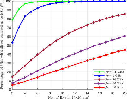
It should be noted that the percentage of UEs supported by the CS via the HAPS-RIS depends on the number of UEs that fail to connect with any terrestrial BS directly. The chances of UEs being supported by the BSs directly depends on the BS and UE densities and the carrier frequency. For a fixed density of BSs, as the density of UEs increases, the percentage of UEs with direct connections drops because the BSs cannot serve more users beyond their maximum loading capacities. Fig. 3 shows how the percentage of UEs with direct connections increases as the density of BSs increases. However, as the carrier frequency increases to provide high data rate communications, the percentage of UEs with direct connections significantly drops, even with the large number of BSs. For instance, four BSs communicating at GHz are sufficient to support more than 80% of UEs directly connected to BSs, whereas more than 20 BSs are required to support 80% of UEs communicating at GHz. Therefore, the HAPS-RIS may offer a more cost-effective solution in such situations than just increasing the density of the BSs.
V-B Comparison Between Allocation Schemes
V-B1 Sum rate and worst UE rate maximization based allocation
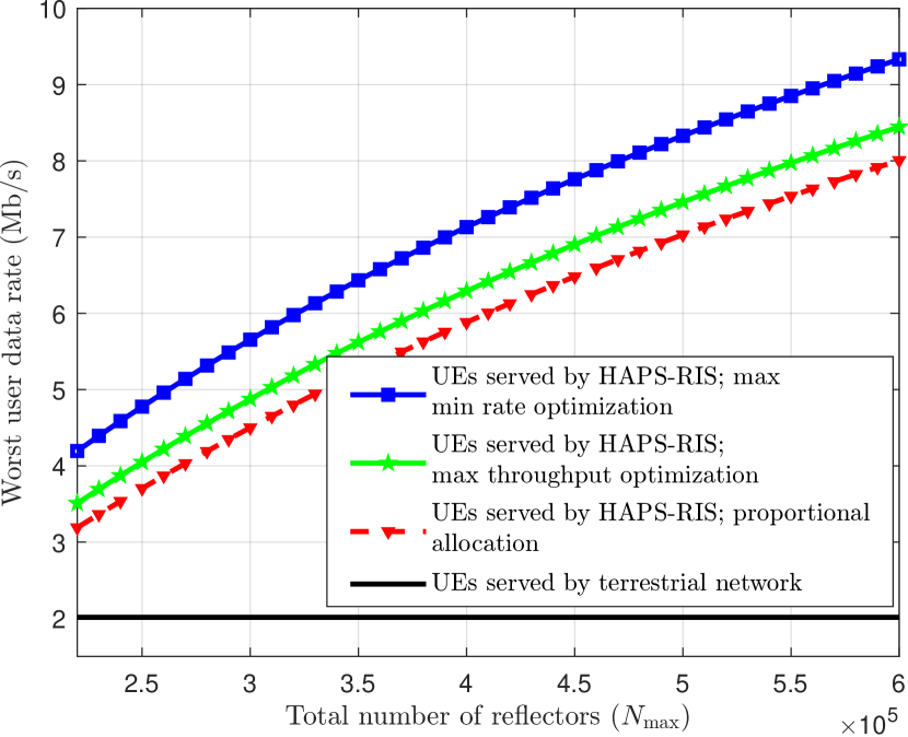
In this simulation, we set , reflectors and dBm and dBm.
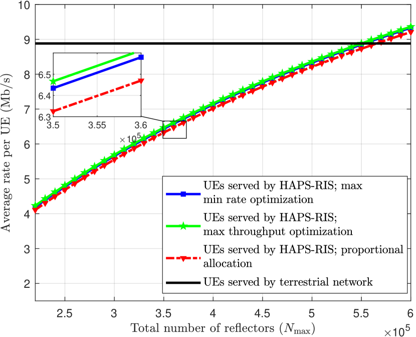
Fig. 4 compares the achievable average and worst rate performances for the UEs belonging to set and . For set , the performance plots are obtained using the optimized power and reflecting units allocation schemes and are compared with the proportional allocation strategy for benchmark purposes.
For the selected range of , i.e., 200,000 – 600,000 reflecting units555This is equivalent to an RIS area between 180 - 540 . This can represent a partial area of a HAPS, as the length of an airship is between 100 and 200 m, whereas an aerodynamic HAPS has wingspans between 35 and 80 m. However, the size of each reflector unit is about [7]., it can be observed that for most of the values of the average rate of the terrestrial UEs is higher than that of the UEs supported by the HAPS-RIS (Fig. 4(a)). This is because the average performance is dominated by the excellent channel conditions between some UEs belonging to set and the BSs. However, for HAPS-RIS to outperform RIS-assisted terrestrial networks in terms of the average rate, should be more than 550,000 reflecting units. Because the rate performance of the worst UE is one of the concerns of network operators, we see in Fig. 4(b) that the rate performance of the worst UE assisted by HAPS-RIS is significantly higher than that are supported by the terrestrial networks.
For the UEs belonging to set , we observe that the max throughput allocation scheme achieved the best performance in terms of average UEs rate. However, in terms of the worst UE performance, the max-min R allocation scheme significantly improves the rate of the UE with the weakest channel gain, and it substantially outperforms the max throughput and the proportional allocation schemes. It should be noted that the improvement in the worst UE rate leads to the degradation of the sum and average UE rates. Since the max min R scheme distributes the system resources fairly and maximizes the fairness among all the UEs, it results in a performance loss for the whole system. It is interesting to note from Fig. 4 that the performance enhancement for the worst UE rate by max min R scheme is about 15%, while the degradation in terms of the average rate or throughput is 1% less than the optimized max throughput allocation scheme.
V-B2 Reflectors Minimization Based Allocation
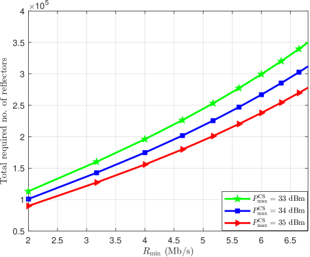
Fig. 5 shows the variation of the minimum number of reflectors required with the different values of the minimum rate requirements of the UE. The number of reflectors and power corresponding to all UEs that satisfy the minimum rate requirements are obtained by solving the problem (IV-C). As we can see, an almost linear relationship exists between the rate requirement and the minimum required number of reflectors. Moreover, by doubling the rate required for the UEs, the RIS unit requirement is increased by 100%. Fig. 5 also shows the relationship between the different values of the maximum transmit power available at the CS () and the optimized number of reflectors. It can be observed that by increasing by 1 dB, the minimum required number of reflectors is reduced by about 11%.
VI Conclusion
In this paper, we introduced the novel concept of beyond-cell communications using HAPS-RIS technology to complement terrestrial networks by supporting unserved UEs. We formulated three resource allocation optimization problems to design the CS power and RIS unit allocation strategies. The optimization objectives included throughput maximization, max min rate, and minimal usage of RIS reflectors. The results showed the capability of beyond-cell communications approach to support a larger number of users with a minimal number of terrestrial BSs. Furthermore, the results showed the superiority of the proposed solutions over the benchmark approach and demonstrated the trade-off between the total and average rate performance and the fairness among UEs.
References
- [1] C. De Alwis, A. Kalla, Q.-V. Pham, P. Kumar, K. Dev, W.-J. Hwang, and M. Liyanage, “Survey on 6G frontiers: Trends, applications, requirements, technologies and future research,” IEEE Open J. Commun. Soc., vol. 2, pp. 836–886, 2021.
- [2] F. Marzouk, J. P. Barraca, and A. Radwan, “On energy efficient resource allocation in shared RANs: Survey and qualitative analysis,” IEEE Commun. Surveys Tuts., vol. 22, no. 3, pp. 1515–1538, Thirdquarter 2020.
- [3] M. A. Kishk and M.-S. Alouini, “Exploiting randomly located blockages for large-scale deployment of intelligent surfaces,” IEEE J. Sel. Areas Commun., vol. 39, no. 4, pp. 1043–1056, Apr. 2020.
- [4] S. Alfattani, W. Jaafar, Y. Hmamouche, H. Yanikomeroglu, A. Yongaçoglu, N. D. Đào, and P. Zhu, “Aerial platforms with reconfigurable smart surfaces for 5G and beyond,” IEEE Commun. Mag., vol. 59, no. 1, pp. 96–102, Jan. 2021.
- [5] M. Di Renzo, A. Zappone, M. Debbah, M.-S. Alouini, C. Yuen, J. De Rosny, and S. Tretyakov, “Smart radio environments empowered by reconfigurable intelligent surfaces: How it works, state of research, and the road ahead,” IEEE J. Sel. Areas Commun., vol. 38, no. 11, pp. 2450–2525, Nov. 2020.
- [6] Y. Liu, X. Liu, X. Mu, T. Hou, J. Xu, M. Di Renzo, and N. Al-Dhahir, “Reconfigurable intelligent surfaces: Principles and opportunities,” IEEE Commun. Surveys Tuts., vol. 23, no. 3, pp. 1546–1577, Thirdquarter 2021.
- [7] G. K. Kurt, M. G. Khoshkholgh, S. Alfattani, A. Ibrahim, T. S. Darwish, M. S. Alam, H. Yanikomeroglu, and A. Yongacoglu, “A vision and framework for the high altitude platform station (HAPS) networks of the future,” IEEE Commun. Surveys Tuts., vol. 23, no. 2, pp. 729–779, Secondquarter 2021.
- [8] S. Alfattani, W. Jaafar, Y. Hmamouche, H. Yanikomeroglu, and A. Yongaçoglu, “Link budget analysis for reconfigurable smart surfaces in aerial platforms,” IEEE Open J. Commun. Soc., vol. 2, pp. 1980–1995, 2021.
- [9] Y. Lu and H. H. Zhou, “Statistical and computational guarantees of Lloyd’s algorithm and its variants,” arXiv preprint arXiv:1612.02099, 2016.
- [10] Study on Channel Model for Frequencies from 0.5 to 100 GHz, 3GPP TR 38.901 V17.0.0, Mar. 2022.
- [11] M. Rivera, M. Chegini, W. Jaafar, S. Alfattani, and H. Yanikomeroglu, “Optimization of quantized phase shifts for reconfigurable smart surfaces assisted communications,” in IEEE 19th Annual Consumer Commun. & Netw. Conf. (CCNC), Las Vegas, USA, 2022, pp. 901–904.
- [12] S. Boyd, S.-J. Kim, L. Vandenberghe, and A. Hassibi, “A tutorial on geometric programming,” Optimization and Engineering, vol. 8, no. 1, pp. 67–127, Apr. 2007.
- [13] Technical Specification Group Radio Access Network; Study on New Radio (NR) to Support Non-Terrestrial Networks, 3GPP TR 38.811 V15.4.0, Sep. 2020.
- [14] Reference Standard Atmospheres, ITU-R P.835-6 P Series, Dec. 2017.