Network-Controlled Physical-Layer Security: Enhancing Secrecy through Friendly Jamming
Abstract
The broadcasting nature of the wireless medium makes exposure to eavesdroppers a potential threat. Physical Layer Security (PLS) has been widely recognized as a promising security measure complementary to encryption. It has recently been demonstrated that PLS can be implemented using off-the-shelf equipment by spectrum-programming enhanced Software-Defined Networking (SDN), where a network controller is able to execute intelligent access point (AP) selection algorithms such that PLS can be achieved and secrecy capacity optimized. In this paper we provide a basic system model for such implementations. We also introduce a novel secrecy capacity optimization algorithm, in which we combine intelligent AP selection with the addition of Friendly Jamming (FJ) by the not-selected AP.
Index Terms:
Artificial Noise, Secrecy, Physical-Layer Security, SDN, Programmable Networks, Friendly JammingI Introduction
Society has become unthinkable without wireless devices. We have become reliant on wireless communication technologies to exchange personal and sometimes confidential data. The broadcasting nature of the wireless medium makes exposure to eavesdroppers a potential threat. So far, this threat has mostly been mitigated by encrypting the wireless link and the information transmitted. Such a solution assumes that eavesdroppers lack the computational resources and knowledge of the network parameters to break the encryption. While this assumption still hold for many scenarios today, eavesdroppers’ capabilities are rapidly improving.
Physical Layer Security (PLS) has been widely recognized as a promising complementary security measure. PLS limits the information that can be intercepted at the bit-level by making it impossible for an eavesdropper to decode any data at the physical layer [1]. If executed well, PLS can thus provide perfect secrecy. Until recently, implementing PLS in a practical and cost-effective way was a challenge [2]. Most techniques proposed in the literature involve major signal-processing efforts to scramble the communication channel effectively for the eavesdropper while simultaneously optimizing the throughput for the legitimate station.
In recent work [3], we demonstrated that PLS can be realized using off-the-shelf equipment by tackling the problem at the network-level. The idea is that a wireless network typically contains not just one wireless access point (AP), but many APs to which a legitimate station could possibly connect. Using a relatively new enhancement of Software-Defined Networking (SDN) specifically for wireless networks, called spectrum programming [4], it is now possible to execute intelligent AP selection algorithms in a way that is completely transparent to the connecting station. We investigated two such algorithms in earlier work. In [3], we had the legitimate station always connect to the AP that is least beneficial to the eavesdropper, and in [5] the AP was selected that maximized the secrecy capacity for the legitimate station. The secrecy capacity is the maximum capacity a legitimate station can achieve under the condition of full secrecy while connected to a given AP.
In this paper, after discussing related work in section II, we provide a basic system model of the proof-of-concept described in [3]. The model enables us to introduce a novel secrecy capacity optimization algorithm, described in section IV, in which we combine intelligent AP selection based on maximizing secrecy capacity [5] with the addition of Friendly Jamming (FJ) by the not-selected AP. In section V we show that providing such a FJ signal to the eavesdroppers significantly improves secrecy in the network beyond what can be achieved with intelligent AP selection. Although the concepts of AP selection and FJ have been suggested earlier in isolation, this is the first time they are combined and supported by a single robust theoretical framework, and in section VI we discuss its applicability in realistic networks.
II Related Work
Techniques proposed in the literature to achieve PLS can be categorized as Channel Coding techniques, Channel Control techniques, Power Control techniques, and Artificial Noise (AN) techniques. Channel coding techniques introduce robust coding schemes and randomization in the transmitted signal to make it difficult for eavesdroppers to decode the intercepted signal [6, 7]. Channel Control focuses on manipulating the radio channel parameter and monitoring the channel to detect the presence of eavesdroppers [8, 9]. Power Control techniques try to achieve secrecy by controlling the power and direction of the signal transmitted to increase the capacity at the legitimate station and degrade the capacity at the eavesdropper, for instance by using multiple antennas [10]. AN techniques, which could also be considered as power control techniques, aim to generate jamming signals to achieve PLS especially in situations where the eavesdropper is closer to the source than the legitimate station. AN-based PLS has been investigated extensively as an approach to achieve PLS for wireless communications. Early work in this area focused on providing AN-based PLS with partial or no knowledge of the Channel State Information (CSI) at the legitimate and eavesdropping stations [11, 12, 13, 14].
These techniques have typically approached the problem at the link-level, focusing on the individual wireless connections between sender and receiver and, so far, have proven to be very hard, if not impossible, to implement. Our earlier work, as presented in [5] and [3], shows a solution by approaching the problem at the network-level using multiple APs and intelligent AP selection. The solution takes advantage of SDN-based spectrum programming as presented in [4], where an enhanced programmable controller has full, up-to-date knowledge of the CSI across the network, and has fine-grained control over the radio parameters of each AP.
In this paper, we show that secrecy in the network can be improved by providing a FJ signal to the eavesdroppers. The idea of FJ in itself is not new. Work presented in [15] and [16] propose an architecture to help realize PLS where two APs, namely AP1 and AP2, are deployed with the legitimate station transmitting data to AP1. During this transmission, AP2 sends a pre-determined signal to AP1, which will act as a jamming signal to any eavesdropping station in the vicinity of the communication. More recent contributions proposing the orchestration of system-level interference to achieve PLS use new techniques such as intelligent reflecting surface [17] and non-orthogonal multiple access [18]. These contributions are all limited to the theoretical domain and do not offer a practical approach to implement the proposed solutions. The novelty of our work lies in enhancing secrecy by combining intelligent AP selection with orchestrated network-controlled generation of FJ in a way that suits today’s hardware and software, supported by a robust theoretical framework.
III System Model
We here consider a wireless system model as shown in Figure 1, where a legitimate station is trying to connect to, and receive information from, a wireless network in the presence of an eavesdropping station. The remainder of the paper assumes the network to be based on 2.4 GHz Wi-Fi, but the concept can easily be generalized to other wireless networks.
It is known that PLS can, in theory, be achieved when the Shannon capacity of the legitimate station is higher than the Shannon capacity of the eavesdropping station (under a range of conditions as laid out in [1]). Without loss of generality, we assume downstream traffic, i.e., from one of the Wi-Fi APs to the legitimate station. This is reasonable for situations where confidential information is provided by servers in the network and is only offered for consumption to legitimate clients.
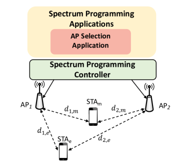
Consider a scenario where there are two APs (denoted by AP1 and AP2), one legitimate station (denoted by STAm) and an eavesdropper (denoted by STAe). We employ the AP selection mechanism proposed in [5] that exploits the principles of PLS to assign the AP that can provide the highest secrecy capacity for STAm. To better explain the AP selection mechanism, a summary of the notation used in this paper is presented in Table I. We assume that the location of the APs, STAm and STAe are known. The latter is of course hard when the eavesdropper is passive, but various proposals have been made in the literature to overcome this problem (see, e.g., [19]). We will discuss this further in Section VI. For simplicity of exposition, we will model the channel between the APs and both stations using a path loss model [20]. Our optimization method is, however, extendable to the case where block-fading CSI is available at the spectrum programming controller.
| APn | Either one of the Access Points ( is either 1 or 2) |
|---|---|
| STAm | Legitimate station |
| STAe | Eavesdropper station |
| Channel bandwidth, Hz | |
| Operating center frequency, Hz | |
| Speed of light, m/s | |
| Transmit power of APn, Watt | |
| Maximum transmit power of APn, Watt | |
| Distance between STAm and APn, m | |
| Distance between STAe and APn, m | |
| Path loss exponent (typical values are: | |
| for free space, | |
| for urban area, | |
| for indoor (line-of-sight)) | |
| Free-space received power from APn at reference distance : , Watt | |
| Distance-corrected power used in capacity formulas: , Watt | |
| SINRn,m | SINR at station STAm when connected to APn |
| SINRn,e | SINR at station STAe when connected to APn |
| Interference experienced at STAm, Watt | |
| Interference experienced at STAe, Watt | |
| Noise experienced by STAm, Watt | |
| Noise experienced by STAe, Watt | |
| Channel capacity between APn and STAm, bits/s | |
| Channel capacity between APn and STAe, bits/s |
Let us assume that APn ( is either 1 or 2) is the considered candidate for downlink data transmission. The received power at STAm and STAe from is and , respectively. Therefore, the Shannon capacity of the channel between APn and the legitimate station STAm is given as
| (1) |
with SINRn,m the Signal to Interference plus Noise Ratio at STAm from APn. Similarly, the Shannon capacity of the channel between APn and the eavesdropper STAe is
| (2) |
where all s are in base 2 and, therefore, capacities are measured in bits/s. The terms and measure the interference experienced at STAm and STAe, respectively, as further elaborated in Section IV.
Based on the principles of PLS, STAm can securely communicate with APn if . The proposed AP selection mechanism in [5] then connects STAm to the AP that provides the maximum secrecy capacity (i.e., maximum value among AP choices or ). Thus, the secrecy capacity is maximized through finding the solution
| (3) |
Therefore, APi is the selected AP for transmission of information to STAm. The other access point APj, is “idle”, as far as data traffic is concerned.
IV Proposed Friendly Jamming
We here propose to have the not-selected AP in (3) (which may also call idle AP) generating an optimal Friendly Jamming (FJ) signal, in addition to employing the AP selection mechanism described in Section III. The idle APj tries to jam STAe to reduce its SINR, which in turns reduces the channel capacity of the eavesdropper () and, therefore, improves the secrecy capacity of STAm. For ease of exposition, we assume that STAe and STAm have the same noise powers for their receivers, i.e. . We also assume that at the time of AP selection based on the mechanism in (3), the ambient interference (without FJ generation) was zero. In our problem formulation and subsequent performance evaluation, this will allow us to evaluate the improvement from optimal FJ generation compared to a baseline system (which is free from ambient/extra interference) in a meaningful way. However, the method presented below can be extended to cater for the general case.
Given the above, the interference experienced by STAm and STAe from the FJ generating APj is and , respectively. Therefore, we specify (1) and (2) as
| (4) |
| (5) |
The goal here is to find the optimal interference power transmitted from APj, i.e. the optimal , to maximize the secrecy capacity of the downlink transmission from APi to STAm. In order to achieve that, we fix the power for the main data APi, , and find the optimal that maximizes defined as follows
| (6) |
To simplify, let us refer to the argument inside the last logarithmic term as . Therefore, can simply be expressed as
| (7) |
where is given by
| (8) |
and and are defined as follows:
| (9) |
The partial derivative of with respect to is
| (10) |
where and are defined as
Let and denote the two quadratic solutions of by . Note that may be negative or go above . Therefore, we need to adjust the above roots according to the physical system constraints:
| (11) |
In addition, two boundary power candidates (no FJ at all) or (max FJ power) also need to be considered. In summary, the optimal FJ power solution is the one among the four candidates that gives the best secrecy capacity . That is,
| (12) |
V Performance Evaluation
In this section, we evaluate the performance of the proposed algorithm in MatLab. We simulated three Wi-Fi systems: a) a normal Wi-Fi system where STAm is associated to the AP with the highest SINR regardless of the eavesdropper’s location; b) the smart AP system based on [5] where STAm is associated to APi that provides the highest secrecy capacity according to (3); and c) the enhanced smart AP where the idle access point APj generates FJ to increase the secrecy of communication between STAm and APi according to (12).
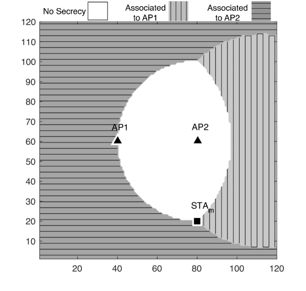
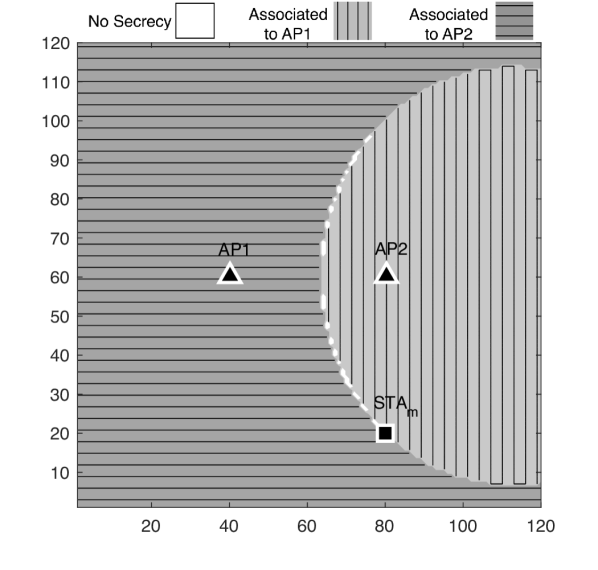
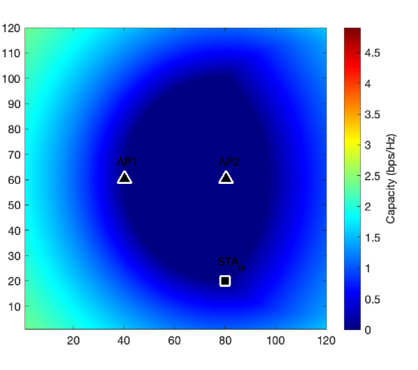
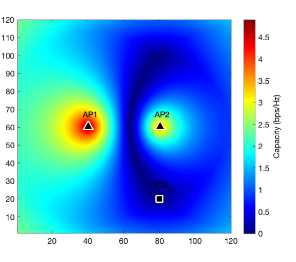
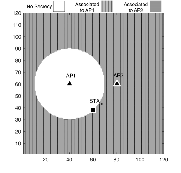
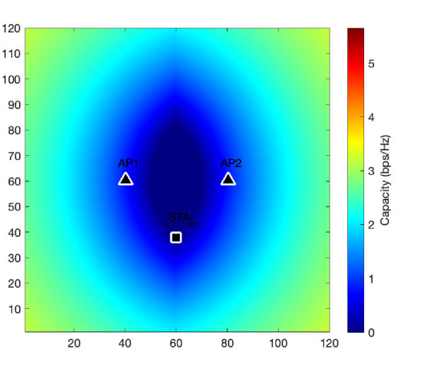
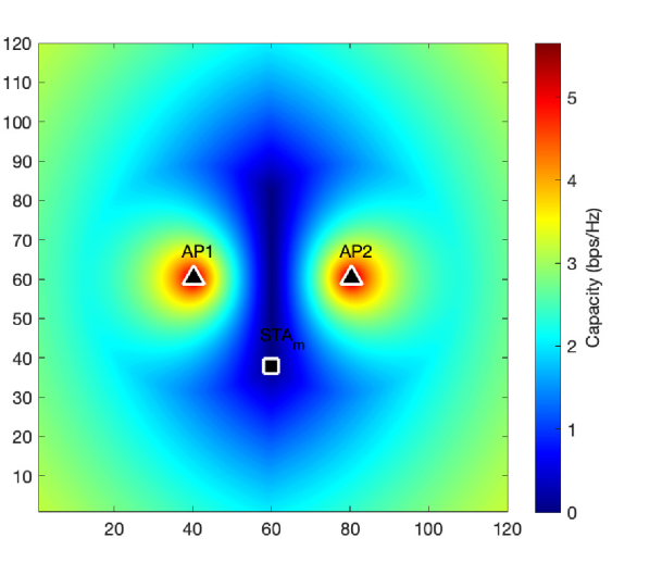
We consider a environment and all coordinates are expressed in meter (m). The two APs are located at positions and and operate at GHz. The AP associated to STAm uses a fixed transmit power of mW. When the idle APj is used to introduce FJ, we assume mW. The noise power at both STAm and STAe is dBm W. A path loss exponent of and a reference distance are assumed for the entire map. Then, for a fixed location of STAm, we run the simulation and for each potential location of STAe, we first select the AP to associate with STAm based on one of the above three methods and then calculate the secrecy capacity , eavesdropping capacity , and the coverage ratio. The latter is the ratio of the area with positive secrecy capacity and the total area of the map, i.e. all locations where the eavesdropper may be located. We repeat the simulations for three different scenarios where STAm is located at position (scenario 1), (scenario 2) and (scenario 3). The results are visualized as a map in Figure 2, 3 and 4, respectively.
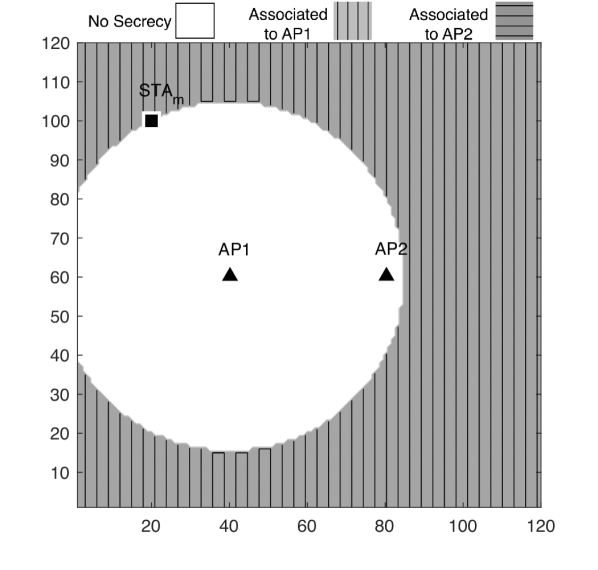
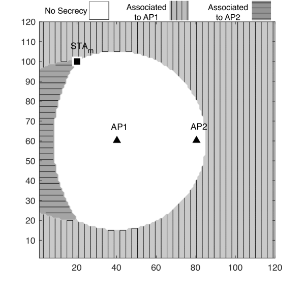
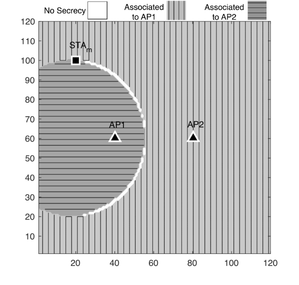
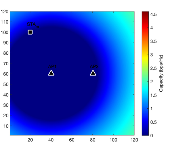
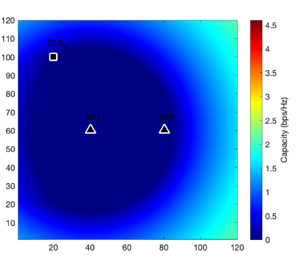
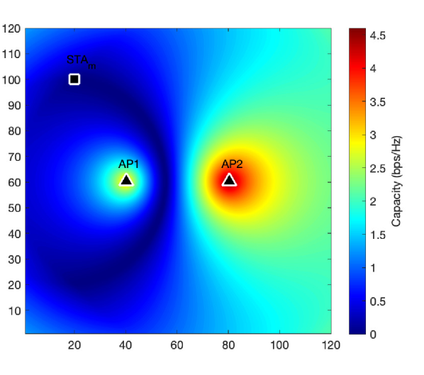
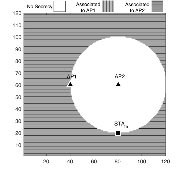
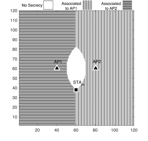
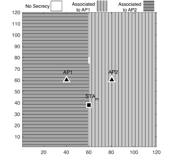
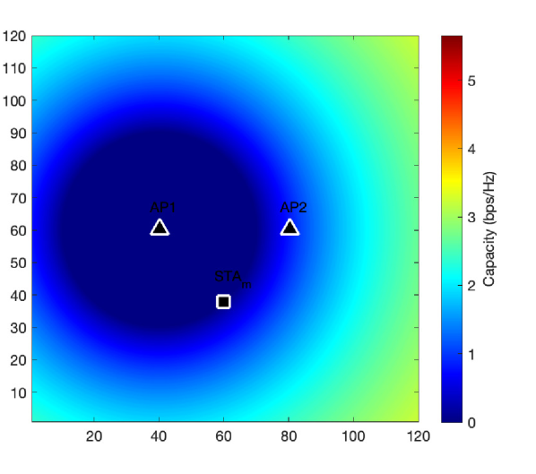
For scenario 1, Figure 2(a) shows for the “normal Wi-Fi” how STAm associates to the AP with the highest received SINR, which is the nearest one. If STAe positions itself closer to this APi, it will be located in the white area, which means that no secrecy can be achieved for STAm. In Figure 2(d) this shows as a secrecy capacity of (zero), i.e. dark blue. Outside this circle, the secrecy capacity is greater than zero. Figure 2(b) and 2(e) illustrate the results for the AP selection algorithm of [5]. The type of shading (horizontal or vertical lines) indicates which AP STAm is connected to, given the location of STAe, such that the secrecy capacity is maximized. Again, if STAe is in the white area, no secrecy can be achieved, regardless of which AP STAm is connected to. But this area is now significantly smaller than in Figure 2(a), showing the effectiveness of the algorithm in [5]. When we now add FJ, the white area almost disappears, as shown in Figure 2(c). This means that, for this scenario, secrecy can be achieved almost everywhere. Figure 2(f) shows that, in this case, the secrecy capacity for STAm has also increased significantly for most locations of STAe.

Results for two other locations of STAm (i.e. scenario 2 and scenario 3) are presented in Figure 3 and 4. From these results we can draw the same conclusions as for scenario 1.
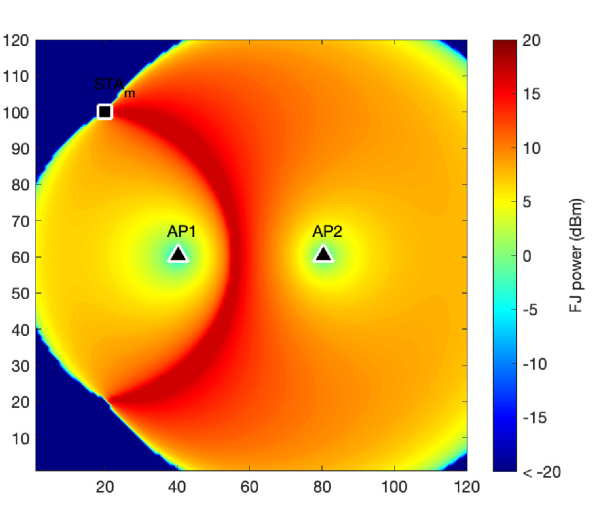
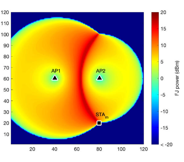
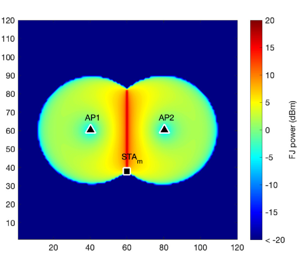
For all three scenarios, Figure 5 illustrates the FJ power that is generated by APj to optimize the capacity and enhance the secrecy coverage. In our simulations, given a constant transmit power of 17 dBm for APi, the FJ power of APj is about 5-10 dBm for the most of potential locations of the eavesdropper to optimize the secrecy capacity for STAm. In contrast, optimal secrecy can be achieved without jamming when the eavesdropper is located on the edge area of the map.
Next, for every scenario and for every algorithm, we calculated the average secrecy capacity and the average eavesdropper’s capacity for all possible locations of STAe. Let STAm and STAe be located at () and (), respectively. The channel capacity of STAm and STAe can then be represented as and , respectively, where , i.e. we vary the location of STAe in steps of 1 m in horizontal or vertical directions. This yields the average secrecy capacity
| (13) |
with . In the same way, we calculate the average eavesdropping capacity as
| (14) |
We then repeated the simulation for 10,000 random locations of STAm.
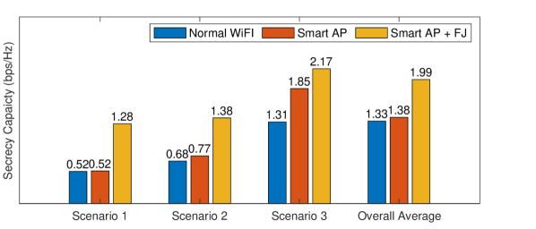
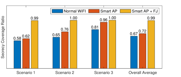
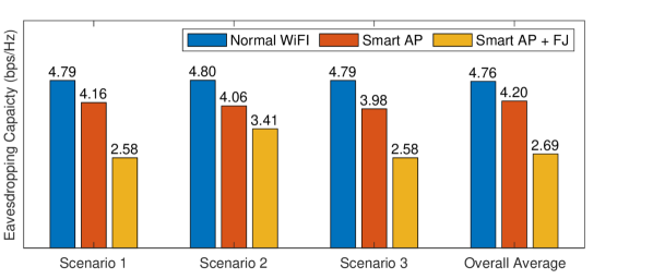
Using (13) and (14), Figure 6 shows the average secrecy capacity for STAm, the average secrecy coverage ratio, and the average eavesdropper’s capacity for the three individual scenarios. The Overall Average shows the results averaged over 10,000 locations for STAm. The color indicates the secrecy capacity optimization algorithm. The results show that the conclusions from Figure 2 can be well generalized to all other locations of STAm. It also shows that adding FJ significantly increases the average secrecy capacity while significantly decreasing the average eavesdropper’s capacity. But, arguably, the most interesting result is that the area where no secrecy can be achieved has reduced to almost zero.
VI Conclusions and Future Work
For a scenario with only two APs controlled by a spectrum-programming enhanced SDN controller, we have shown that perfect secrecy and optimized secrecy capacity can be achieved by means of network-enabled PLS, for nearly every location of the passive eavesdropper, by intelligently combining AP selection for the legitimate station and the generation of FJ by the idle AP. This is an important result, as until now, the applicability of PLS in real networks has greatly suffered under the complexity of its implementation and the inability to secure the network for too many locations of an eavesdropper. Our work shows that both limitations can be overcome by looking at the problem at the level of a programmable network.
In future work, we will optimize the model and the system further by adding more APs, more legitimate stations, and more eavesdroppers. It can be intuitively understood that a larger scale and a higher density of the wireless network provides more opportunities to further optimize AP selection as well as the generation of FJ. We also intend to validate our simulation results with our testbed as described in [3]. There are also many opportunities to improve the algorithms further. For instance, we here optimized the secrecy capacity by AP selection and FJ in a serial manner: first AP selection, then FJ. The next step is to optimize both mechanisms jointly. The model may also extended by the inclusion of other techniques such as multiple antennae, beamforming and network coding.
Throughout this paper, we have assumed that the eavesdropper’s channel condition is known, and therefore its location. This is particularly hard when the eavesdropper is passive. To mitigate this, we will investigate if we can consider the physical boundaries of the network, for instance an enterprise building or apartment block. This makes it possible to distinguish insider threats from external eavesdroppers, and to make statistical estimates for the likely locations of the external eavesdroppers. We will also investigate the use of effective eavesdropper detection tools such as Ghostbuster [19], which make use of the fact that even passive receivers leak RF signals, which can be integrated into the spectral programming architecture.
We will also look at cases where upstream traffic needs to be confidential too. The relevant eavesdropper’s Shannon capacity is then between STAe and STAm. This is outside the control of the spectrum programming architecture, unless STAm is also a controlled entity. PLS can then in theory be achieved by moving the AP closer to the STAm. However, the STAe may still be able to decode the signal unless link-level measures are being applied in addition.
Acknowledgment
This work is supported by the UNSW Institute for Cyber Security (IFCYBER) and an internal grant from the School of Engineering and IT, UNSW Canberra.
References
- [1] A. D. Wyner, “The wire-tap channel,” Bell system technical journal, vol. 54, no. 8, pp. 1355–1387, 1975.
- [2] K. S. Ryland, “Software-defined radio implementation of two physical layer security techniques,” Ph.D. dissertation, Virginia Tech, 2018.
- [3] S. A. Hoseini, F. Bouhafs et al., “A practical implementation of physical layer security in wireless networks,” in 2022 IEEE 19th Annual Consumer Communications Networking Conference (CCNC), 2022, pp. 1–4.
- [4] F. Bouhafs, M. Mackay et al., “Wi-5: A programming architecture for unlicensed frequency bands,” IEEE Communications Magazine, vol. 56, no. 12, pp. 178–185, 2018.
- [5] F. Bouhafs, F. den Hartog et al., “Realizing physical layer security in large wireless networks using spectrum programmability,” in 2020 IEEE Globecom Workshops, 2020, pp. 1–6.
- [6] W. K. Harrison, J. Almeida et al., “Coding for secrecy: An overview of error-control coding techniques for physical-layer security,” IEEE Signal Processing Magazine, vol. 30, no. 5, pp. 41–50, 2013.
- [7] W. K. Harrison and S. W. McLaughlin, “Physical-layer security: Combining error control coding and cryptography,” in 2009 IEEE International Conference on Communications, 2009, pp. 1–5.
- [8] C. Sperandio and P. G. Flikkema, “Wireless physical-layer security via transmit precoding over dispersive channels: optimum linear eavesdropping,” in MILCOM - IEEE Military Communications Conference, vol. 2, 2002, pp. 1113–1117.
- [9] X. Li and E. P. Ratazzi, “MIMO transmissions with information-theoretic secrecy for secret-key agreement in wireless networks,” in MILCOM - IEEE Military Communications Conference, 2005, pp. 1353–1359.
- [10] X. Chen, D. W. K. Ng et al., “A survey on multiple-antenna techniques for physical layer security,” IEEE Communications Surveys & Tutorials, vol. 19, no. 2, pp. 1027–1053, 2016.
- [11] S. Liu, Y. Hong et al., “Practical secrecy using artificial noise,” IEEE Communications Letters, vol. 17, no. 7, pp. 1483–1486, 2013.
- [12] P.-H. Lin, S.-H. Lai et al., “On secrecy rate of the generalized artificial-noise assisted secure beamforming for wiretap channels,” IEEE Journal on Selected Areas in Communications, vol. 31, no. 9, pp. 1728–1740, 2013.
- [13] S.-H. Tsai and H. V. Poor, “Power allocation for artificial-noise secure MIMO precoding systems,” IEEE transactions on signal processing, vol. 62, no. 13, pp. 3479–3493, 2014.
- [14] X. Zhang, X. Zhou et al., “On the design of artificial-noise-aided secure multi-antenna transmission in slow fading channels,” IEEE Transactions on Vehicular Technology, vol. 62, no. 5, pp. 2170–2181, 2013.
- [15] M. L. Jorgensen, B. R. Yanakiev et al., “Shout to secure: Physical-layer wireless security with known interference,” in IEEE GLOBECOM 2007-IEEE Global Telecommunications Conference, 2007, pp. 33–38.
- [16] J. P. Vilela, M. Bloch et al., “Wireless secrecy regions with friendly jamming,” IEEE Transactions on Information Forensics and Security, vol. 6, no. 2, pp. 256–266, 2011.
- [17] S. Hong, C. Pan et al., “Artificial-noise-aided secure MIMO wireless communications via intelligent reflecting surface,” IEEE Transactions on Communications, vol. 68, no. 12, pp. 7851–7866, 2020.
- [18] C. Gong, X. Yue et al., “Enhancing physical layer security with artificial noise in large-scale noma networks,” IEEE Transactions on Vehicular Technology, vol. 70, no. 3, pp. 2349–2361, 2021.
- [19] A. Chaman, J. Wang et al., “Ghostbuster: Detecting the presence of hidden eavesdroppers,” in Proceedings of the 24th Annual International Conference on Mobile Computing and Networking, 2018, pp. 337–351.
- [20] A. Goldsmith, Wireless communications. Cambridge university press, 2005.