Optimal Design of Energy-Harvesting Hybrid VLC/RF Networks
††thanks: This work is supported in part by NSF under the grant CNS-1910153.
Abstract
In this paper, we consider an indoor downlink dual-hop hybrid visible light communication (VLC)/radio frequency (RF) scenario. For each transmission block, we dynamically allocate a portion of time resources to VLC and the other portion to RF transmission. In the first phase (i.e., VLC transmission), the LED carries both data and energy to an energy harvester relay node. In the second phase (i.e., RF communication), the relay utilizes the harvested energy to re-transmit the decoded information to the far RF user. During this phase, the LED continues to transmit power (no information) to the relay node, aiming to harvest energy that can be used in the next transmission block. We formulate the optimization problem in the sense of maximizing the data rate under the assumption of decode-and-forward (DF) relaying. As the design parameters, the direct current (DC) bias and the assigned time duration for VLC transmission are taken into account. In particular, the joint non-convex optimization is split into two sub-problems, which are then cyclically solved. In the first sub-problem, we fix the assigned time duration to VLC link and utilize the majorization-minimization (MM) procedure to solve the non-convex DC bias problem. In the second sub-problem, we fix the DC bias obtained in the previous step and solve the optimization problem for the assigned VLC link time duration. Our results demonstrate that a higher data rate can be achieved by solving the joint problem of DC bias and time duration compared to solely optimizing the DC bias.
Index Terms:
Hybrid VLC-RF, DC bias, Energy harvesting, information rate.I Introduction
Visible light communications (VLC) is a promising complementary technology to radio-frequency (RF) based wireless systems, as it can be used to offload users from RF bands for releasing spectrum resources for other users while also simultaneously providing illumination [1]. Recently, hybrid VLC- RF systems are receiving attention in the literature, which can be designed to take advantage of both technologies, e.g., high-speed data transmission by VLC links while achieving seamless coverage through RF links [2]. In particular, a hybrid VLC-RF system is desirable for indoor applications such as the Internet of things (IoT) or wireless sensor networks [3]. Given that power constraint is a key performance bottleneck in such networks, a potential approach is to scavenge energy from the surrounding environment through energy harvesting (EH).
There have been some recent studies on enabling EH for a dual-hop hybrid VLC-RF communication system where the relay can harness energy from a VLC link (first hop), for retransmitting the data to the end user over the RF link (second hop). For example, an optimal design in the sense of maximizing the data rate with respect to the direct current (DC) bias by allocating an equal time portion for VLC and RF transmission is introduced in [4]. In another work, both energy and spectral efficiency are investigated in [5] by taking into account the power consumption of the light emitting diodes (LEDs), which clearly shows the trade-off between energy and spectral efficiency and the importance of optimizing the DC bias. In [6], the relay is chosen among multiple IoT devices which are randomly distributed within the coverage of the source. Based on the channel state information, an analytical approach is used to determine the end-to-end outage probability for two different transmission schemes. In [7], Peng et al. consider a mobile relay to facilitate the communications between the source and destination. The end-to-end outage probability of the system is analytically obtained and compared with the simulation results. They further extend this work and study the minimization problem of end-to-end outage probability under the constraints of both the average and the peak powers of the LED source in [8]. In [9], a hybrid VLC-RF ultra-small network is introduced where the optical transmitters deliver both the lightwave information and energy signals whereas a multiple-antenna RF access point (AP) is employed to transfer wireless power over RF signals.
The current literature on hybrid VLC-RF systems that also use EH is mainly limited to finding the optimal value of DC bias to either maximize the data rate or minimize the outage probability [4, 5, 7]. To our best knowledge, optimization of VLC and RF resources for hybrid RF/VLC links for a scenario such as in Fig. 1 is not studied in the literature. In this paper, we investigate the performance of EH for an indoor hybrid VLC-RF scenario as in Fig. 1. We dynamically allocate a portion of each transmission block to VLC and the rest to RF transmission. The LED transmits both data and energy to a relay node with energy harvesting capability in the first phase as illustrated in Fig. 2 (i.e., VLC transmission). During the second phase (RF communication), the relay transmits the decoded information to the distant RF user using the harvested energy. Also, during this phase, the LED continues to transmit power (no information) to the relay node, aiming to harvest energy that can be utilized by the RF relay in the next transmission block.
For this specific scenario, we formulate an optimization problem for maximizing the data rate at the far user. In particular, we consider both the DC bias and the assigned time duration to VLC link as the design parameters. We split the joint non-convex optimization problem into two sub-problems and cyclically solve them. First, we fix the assigned time duration for VLC transmission and solve the non-convex problem for DC bias by employing the majorization-minimization (MM) procedure [10, 11]. Second, we fix the DC bias obtained from the previous step and solve the optimization problem for the assigned time duration to VLC link.
The remainder of this paper is organized as follows. In Section II, we describe our system model. The end-to- end data rate is formulated in Section III along with the respective optimization problem and our approach to solve the optimization problem. The numerical results are presented in Section IV, and finally, the paper concludes with Section V.
II System Model
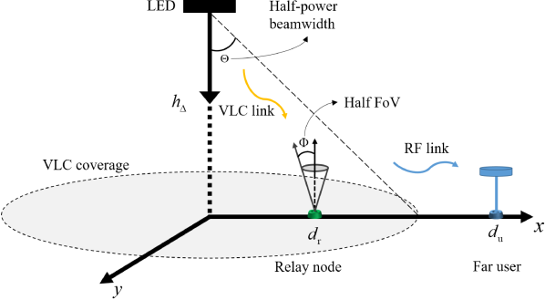
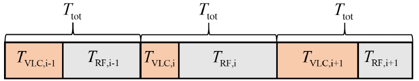
Fig. 1 illustrates the hybrid VLC-RF system under consideration. We assume a relay equipped with a single photo-detector (PD), energy-harvesting circuity, and a transmit antenna for RF communications. Let denote the block transmission time which is measured in seconds. Also, (unitless value) is the portion of time that is allocated to transmit information and energy to the relay node in the time block. Thus, the duration of this phase in seconds is . We assume that the block transmission time is constant. Hereafter, we drop the superscript of in the sequel to simplify notation. Fig. 2 depicts the transmission block under consideration. Without loss of generality, we assume that second.
II-A VLC Link
In the first hop, the LED transmits both energy and information to the relay node through the VLC link. The non-negativity of the transmitted optical signal can be assured by adding DC bias (i.e., ) to the modulated signal, i.e., where denotes the LED power per unit (in W/A) and is the modulated electrical signal. We assume that the information-bearing signal is zero-mean, and satisfies the peak-intensity constraint of the optical channel such that [12]
| (1) |
where denotes the peak amplitude of the input electrical signal (i.e., ), and with and being the maximum and minimum input currents of the DC offset, respectively. Let denote the double-sided signal bandwidth.
Then, the information rate associated with the optical link between the AP and relay node within a block with second, is given as [12]
| (2) |
where is the photo-detector responsivity in A/W and is the optical DC channel gain. In (2), is the power of shot noise at the PD which is given as where is the charge of an electron and is the induced current due to the ambient light. The optical DC channel gain of the VLC link can be written as
| (3) |
where and are the vertical and horizontal distances, respectively, between AP and the relay node, and and are the respective angle of irradiance and incidence, respectively. The Lambertian order is where is the half-power beamwidth of each LED, and and are the detection area and half field-of-view (FoV) of the PD, respectively. The function is 1 whenever , and is 0 otherwise. We also assume that the relay node distance follows a Uniform distribution with , and that relay PD is looking directly upward.
The harvested energy at this phase can be computed as
| (4) |
where is the thermal voltage, is the dark saturation current, and is the DC part of the output current given as . In the time period , the aim is to maximize the harvested energy while the relay transmits the information to the far user over the RF link. Thus, during second phase the LED eliminates the alternating current (AC) part and maximizes the DC bias, i.e., and . Mathematically speaking, the harvested energy during the second phase can be expressed as
| (5) |
where . The total harvested energy at the relay that can be utilized for transmitting the decoded symbol to the far user through an RF link can be calculated as
| (6) |
where , represents the harvested energy during the RF transmission in the previous transmission block. In this paper, we assume that the initial harvested energy is 0 (i.e., ).
As it can be readily checked from (1), increasing leads to a decrease in and, consequently, it decreases the information rate associated with the VLC link. On the other hand, decreasing limits the harvested energy that can be obtained during VLC transmission (i.e., ).
II-B RF Link
In the second hop, the relay re-transmits the information to the far user through the RF link by utilizing the harvested energy. The relaying operation is of decode-and-forward (DF) type. We assumed that the user is off the AP horizontally by a distance , which follows a Uniform distribution with . Let denote the bandwidth for the RF system and denote the noise power which can be defined as where is the thermal noise power, and is the noise figure. Further, assume that the relay re-transmits the electrical signal with normalized power. The respective information rate is given as
| (7) |
where denotes the Rayleigh channel coefficients, is the transmit power and is the path loss model for RF link and can be expressed as
| (8) |
where being the used RF carrier wavelength, m is the reference distance, and is the path loss exponent, which generally takes value between [1.6, 1.8].
The achievable information rate is limited by the smaller information rate between the VLC link and the RF link and can be expressed as [13]
| (9) |
III Optimization Framework and Solution
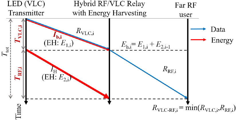
Fig. 3 illustrates the summary of our optimization problem in which , and are considered as the optimization variables to maximize the system data rate. Recalling the information rate in VLC link (i.e., (2)) and RF link (i.e., (6)), the optimization problem can be written as
| (10) | ||||
| s.t. | ||||
where is a predefined threshold value, constraints and are imposed to avoid any clipping and guarantee that the LED operates in its linear region and is added to satisfy the minimum required data rate. The above joint-optimization problem is non-smooth (due to the operator) and non-convex (due to the objective function and constraint ). We reformulate the above optimization problem in the epigraph form to remove the non-smoothness in the objective function. The epigraph form of (10) can be written as
| (11) | ||||
| s.t. | ||||
The above equivalent optimization problem to (10) solves the non-smoothness, while it is still non-convex. Let , , and . Substituting (2) and (7) in (11), we have
| (12) | ||||
| s.t. | ||||
In the above optimization problem, is used in and is still non-smooth. Here, we relax by using the Proposition 1 from [13]. Intuitively, the higher the term higher the energy harvesting, however, a negative effect on the rate beyond . Thus, the optimal value of the term would be within and (and not the other regime . The above restriction enforces benefiting in getting rid of the non-smooth operator (see (12)) as well. This leads to and . The constraints are jointly non-convex. In this regard, we split the joint optimization problem into two sub-problems and solve them in a cyclic fashion.
III-A Sub-problem 1
First, we fix (and hence ) and solve the maximization problem for over . Sub-problem 1 can be written as
| (13) | ||||
| s.t. | ||||
where the constraints are conditionally convex.
Assumption: The typical illumination requirement in an indoor VLC environment results in a high transmit optical intensity, which can provide a high signal-to-noise ratio (SNR) at the receiver [14, 15]. In this paper, we assume that SNR for the VLC link is much greater than 1 (in linear scale); i.e., . In this condition, we further utilize in the constraints . Thus, the optimization problem can be written as
| (14) | ||||
| s.t. | ||||
In (14), is a convex constraint while is still not convex. We further utilize the first-order Taylor series and MM approach to relax this constraint [10, 11]. As a result, can be replaced with
| (15) |
where
| (16) | ||||
and
| (17) |
In (15), the term is an index-term and denotes the iteration index for the MM approach. The MM procedure on (15) operates iteratively. We first solve the problem for some initial values of . Then, we update the value of at each iteration until it remains the same for two consecutive iterations, or the change between two consecutive iterations is not appreciable.
Overall, the optimization sub-problem 1 is as follows:
| (18) | ||||
| s.t. |
We iteratively solve the above sub-problem 1 until its convergence. Once the above sub-problem converges, we continue with sub-problem 2 which is elaborated in the following.
III-B Sub-problem 2
In here, we fix obtained from sub-problem 1 and solve the problem for maximizing over the variables . The optimization problem can be expressed as
| (19) | ||||
| s.t. |
In (19), the objective function and constraints are linear, whereas the constraints and are convex constraints which result in a convex optimization problem.
| Parameter | Numerical Value |
|---|---|
| User distance (,) | [4,8] m |
| Relay distance (,) | [0,2] m |
| LED power () | 1.5 W/A |
| Noise figure () | 9 dB [5] |
| RF signal bandwidth | 10 MHz [13] |
| VLC signal bandwidth | 10 MHz [13] |
| Thermal noise () | -174 dBm/Hz [5] |
| RF frequency () | {2.4, 5} GHz [5] |
| Minimum DC bias () | 100 mA [5] |
| Maximum DC bias () | 1 A [5] |
| Photo-detector responsivity ( ) | 0.4 A/W [12] |
| Thermal voltage () | 25 mV [5] |
| Dark saturation current () | A [5] |
| Half FoV () | [5] |
| Half-power beamwidth () | [5] |
| Electron charge () | |
| Induced current () | [5] |
| PD detection area () | [5] |
| AP relative height () | 2 m [5] |
| Data rate threshold () | b/s |
IV Numerical Results
In this section, we demonstrate the performance of hybrid VLC-RF scheme under consideration as in Fig. 1. For the convenience of the reader, the channel and system parameters are summarized in Table I. We consider four distinct cases:
-
•
Case 1: Joint optimization (JO) of and with utilizing the harvested energy from previous transmission block, i.e., ;
-
•
Case 2: JO of and without utilizing the harvested energy from previous transmission block, i.e., ;
-
•
Case 3: Optimization of for fixed time allocation (FTA), i.e., , with utilizing the harvested energy from previous transmission block, i.e., (similar to [4]);
-
•
Case 4: Optimization of for FTA, i.e., , without utilizing the harvested energy from previous transmission block, i.e., . Similar condition was considered in [8].
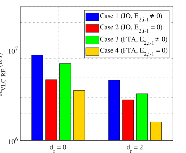
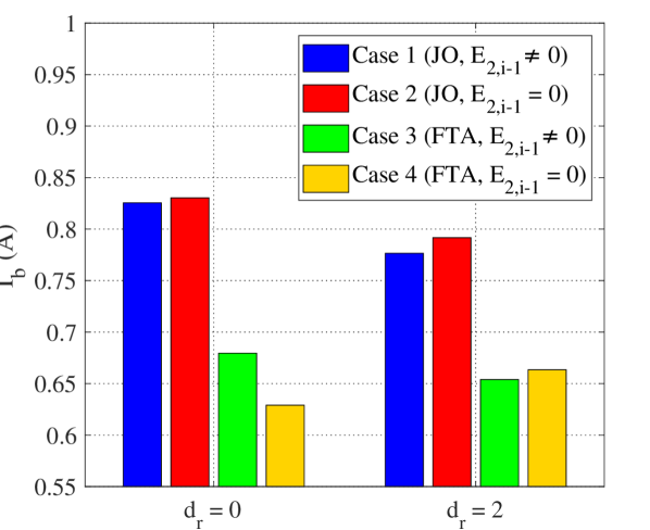
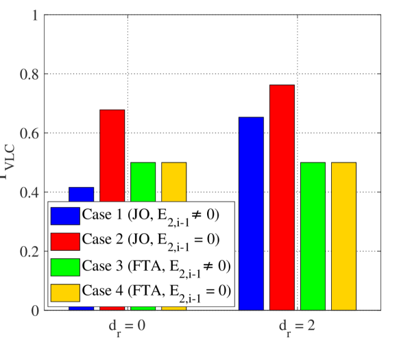
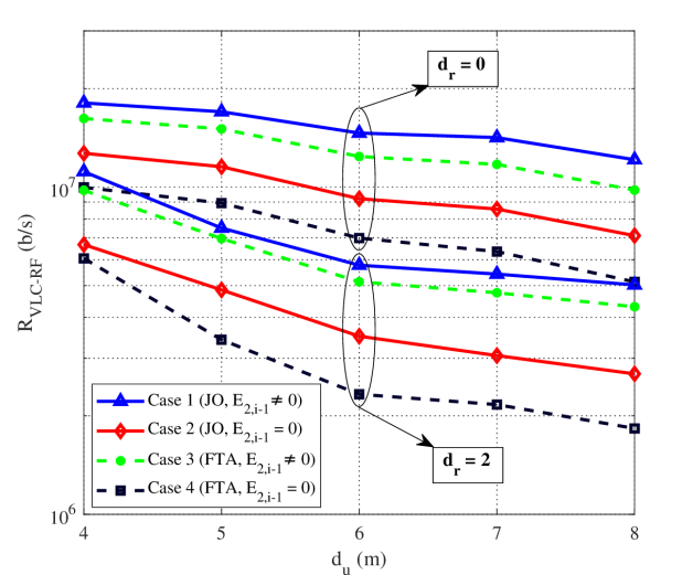
Fig. 4 depicts the performance of optimal data rate when the relay is located at and m. The user distance varies as . We assume RF frequency as GHz. It can be observed that Case 1 and Case 3, where the relay can harvest energy during RF transmission, outperform the other cases. Note the optimal data rate for all cases decreases as the user distance increases. Since the relay node is fixed and the achievable information rate is limited by the smaller information rate between the VLC link and the RF link, one can conclude that the restriction in the system under consideration comes from the RF link. In such energy-deprived regimes, harvesting the energy during the second-hop RF transmission (as proposed in our work) benefits significantly in increasing the bottle-necked data rate.
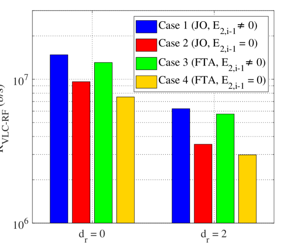
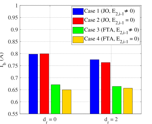
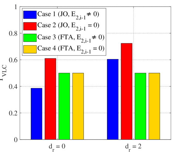
Fig. 5 illustrates the performance of system under consideration assuming the relay location varies as and the user node distance follow Uniform distribution with . Here, the RF frequency is assumed as GHz. As it can be observed from Fig. 5(a), solving the joint optimization over and leads to a higher data rate compared with the other considered cases. In addition, Fig. 5(a) clearly shows that harvesting energy during RF transmission (Case 1 and Case 3) results in an increase in optimal data rate. To investigate the reason behind this outperforming, we further depict the optimal DC bias and the time duration assigned for VLC link in 5(b) and 5(c), respectively. The optimal value of DC bias for the joint optimization (regardless of harvesting energy during RF transmission) is higher than the ones obtained when as shown in Fig. 5(b). Recalling , this leads to a smaller amount of peak amplitude of the input electrical signal which consequently limits the VLC data rate. In addition, it can be observed that the optimal value of for Case 1 is less than 0.5 which accordingly restrains the data rate of the VLC link (cf. (2)). Although the difference between the optimal DC bias for Case 1 and Case 2 is practically negligible, optimal for Case 2 is much higher than Case 1. For Case 2, the power of the relay only relies on the harvested energy during VLC transmission (according to (4)) which can be increased by allocating more time for this phase. This behavior is because Case 2 ignores harvesting energy during RF transmission and allocating more time for VLC transmission aims to compensate for this effect.
To study the effect of RF frequency, Fig. 6 depicts the performance of system under consideration with GHz when the user node distance follows and the relay location varies as . Comparing Fig. 6(a) and Fig. 5(a) shows that the optimal data rate decreases as the RF frequency increases. According to (8), as RF frequency increases the effect of path loss becomes more pronounced. To further investigate the behavior of the optimization problems, the optimal DC bias and the time duration assigned for the VLC link in Fig. 6(b) and Fig. 6(c), respectively. For Case 1 and Case 2, the optimal DC bias decreases as the relay distance (i.e., ) increases which leads to a decrease in the VLC data rate. Comparing Fig. 6(c) and Fig. 5(c) indicates that the optimal time duration for VLC transmission increases as the RF frequency increases.
V Conclusion
In this paper, we proposed an EH hybrid VLC-RF scheme where the relay harvests energy both during VLC transmission and RF communication. With DF relaying assumed, we have formulated the optimization problem to maximize achievable data rate. In addition to the DC bias, we considered the assigned time duration for VLC transmission as a design parameter. Specifically, the joint optimization problem was divided into two sub-problems and solved cyclically. Our first sub-problem involved fixing the time duration for VLC transmission and solving the non-convex DC bias problem using MM approach. In the second sub-problem, we solved the optimization problem for the assigned VLC link time duration using the DC bias obtained in the previous step. The results have shown that our proposed joint optimization approach achieves a higher data rate compared to solely optimizing the DC bias.
References
- [1] H. Burchardt, N. Serafimovski, D. Tsonev, S. Videv, and H. Haas, “VLC: Beyond point-to-point communication,” IEEE Commun. Mag., vol. 52, no. 7, pp. 98–105, 2014.
- [2] D. A. Basnayaka and H. Haas, “Hybrid RF and VLC systems: Improving user data rate performance of VLC systems,” in Proc. IEEE Vehicular Technology Conference (VTC), Glasgow, U.K., May 2015, pp. 1–5.
- [3] F. Delgado-Rajo, A. Melian-Segura, V. Guerra, R. Perez-Jimenez, and D. Sanchez-Rodriguez, “Hybrid RF/VLC network architecture for the Internet of Things,” Sensors, vol. 20, no. 2, p. 478, 2020.
- [4] T. Rakia, H.-C. Yang, F. Gebali, and M.-S. Alouini, “Optimal design of dual-hop VLC/RF communication system with energy harvesting,” IEEE Commun. Lett., vol. 20, no. 10, pp. 1979–1982, 2016.
- [5] Y. Yapıcı and İ. Güvenç, “Energy-vs spectral-efficiency for energy-harvesting hybrid RF/VLC networks,” in Proc. Asilomar Conference on Signals, Systems, and Computers, Pacific Grove, CA, Nov. 2020, pp. 1152–1156.
- [6] Z. Zhang, Q. Li, H. Peng, A. Pandharipande, X. Ge, and J. Zhang, “A SLIPT-based hybrid VLC/RF cooperative communication system with relay selection,” in Proc. IEEE/CIC Int. Conf. Commun. China (ICCC), Chongqing, China, 2021, pp. 277–282.
- [7] H. Peng, Q. Li, A. Pandharipande, X. Ge, and J. Zhang, “Performance analysis of a SLIPT-based hybrid VLC/RF system,” in Proc. IEEE/CIC Int. Conf. Commun. China (ICCC), Chongqing, China, Aug. 2020, pp. 360–365.
- [8] ——, “End-to-end performance optimization of a dual-hop hybrid VLC/RF IoT system based on SLIPT,” IEEE Internet Things J., vol. 8, no. 24, pp. 17 356–17 371, 2021.
- [9] H.-V. Tran, G. Kaddoum, P. D. Diamantoulakis, C. Abou-Rjeily, and G. K. Karagiannidis, “Ultra-small cell networks with collaborative RF and lightwave power transfer,” IEEE Trans. Commun., vol. 67, no. 9, pp. 6243–6255, 2019.
- [10] Y. S. Eroglu, C. K. Anjinappa, I. Guvenc, and N. Pala, “Slow beam steering and NOMA for indoor multi-user visible light communications,” IEEE Trans. Mobile Comput., vol. 20, no. 4, pp. 1627–1641, 2019.
- [11] Y. Sun, P. Babu, and D. P. Palomar, “Majorization-minimization algorithms in signal processing, communications, and machine learning,” IEEE Trans. Signal Process., vol. 65, no. 3, pp. 794–816, 2016.
- [12] P. D. Diamantoulakis, G. K. Karagiannidis, and Z. Ding, “Simultaneous lightwave information and power transfer (SLIPT),” IEEE Trans. Green Commun. Netw., vol. 2, no. 3, pp. 764–773, 2018.
- [13] Y. Guo, K. Xiong, Y. Lu, D. Wang, P. Fan, and K. B. Letaief, “Achievable information rate in hybrid VLC-RF networks with lighting energy harvesting,” IEEE Trans. Commun., vol. 69, no. 10, pp. 6852–6864, 2021.
- [14] L. Hanzo, H. Haas, S. Imre, D. O’Brien, M. Rupp, and L. Gyongyosi, “Wireless myths, realities, and futures: From 3G/4G to optical and quantum wireless,” Proceedings of the IEEE, vol. 100, no. Special Centennial Issue, pp. 1853–1888, 2012.
- [15] J.-Y. Wang, C. Liu, J.-B. Wang, Y. Wu, M. Lin, and J. Cheng, “Physical-layer security for indoor visible light communications: Secrecy capacity analysis,” IEEE Transactions on Communications, vol. 66, no. 12, pp. 6423–6436, 2018.