Beam Aware Stochastic Multihop Routing for Flying Ad-hoc Networks
††thanks: This project has received funding from the European Union’s Horizon 2020 research and innovation program under the Marie Skłodowska-Curie Grant agreement No. 813999. The work of A. Pastore and X. Mestre was supported by Grant RTI2018-099722-B-I00 funded by MCIN/AEI/10.13039/501100011033 and by “ERDF A way of making Europe”. The author affiliations and emails are as follows:
1Department of Information Engineering, University of Padova, Italy. Emails: {deshpande,zanella}@dei.unipd.it
2Research Unit for Information and Signal Processing for Intelligent Communications (ISPIC),
Centre Tecnològic Telecomunicacions de Catalunya, Barcelona, Spain. Emails: {rpereira,apastore,xmestre}@cttc.es
3Department of Electronic Systems, Aalborg University, Denmark. Email: fchi@es.aau.dk
Abstract
Routing is a crucial component in the design of Flying Ad-Hoc Networks (FANETs). State of the art routing solutions exploit the position of Unmanned Aerial Vehicles (UAVs) and their mobility information to determine the existence of links between them, but this information is often unreliable, as the topology of FANETs can change quickly and unpredictably. In order to improve the tracking performance, the uncertainty introduced by imperfect measurements and tracking algorithms needs to be accounted for in the routing. Another important element to consider is beamforming, which can reduce interference, but requires accurate channel and position information to work. In this work, we present the Beam Aware Stochastic Multihop Routing for FANETs (BA-SMURF), a Software-Defined Networking (SDN) routing scheme that takes into account the positioning uncertainty and beamforming design to find the most reliable routes in a FANET. Our simulation results show that joint consideration of the beamforming and routing can provide a 5% throughput improvement with respect to the state of the art.
Index Terms:
Flying Ad-Hoc Networks, mmWave Communication, Beamforming, Position UncertaintyI Introduction
Unmanned Aerial Vehicles (UAVs) are used in a wide range of applications, from tracking and monitoring animals in remote areas[1] to military applications[2]. In order to effectively accomplish tasks over wider areas, it can be necessary to deploy multiple UAVs, which are expected to coordinate actions in an autonomous fashion or execute direct instructions from a control center, all of which are relayed through a Flying Ad-Hoc Network (FANET).
In many scenarios, the UAVs need to exchange a relatively large amount of data with other members of the swarm and/or with the control station to support a given service. For example, distributed area monitoring/patrol applications may require the UAVs to stream high definition video or thermal camera recordings to the control station. Conversely, high bit rate data traffic demands wideband communication technologies (e.g., mmWave) that typically have limited coverage range, so that providing such services over wide areas may require multi-hop data connections, where the UAVs themselves can act as relays for other nodes in the network [3].
On the other hand, the UAVs and the control station also need to exchange light control traffic, which usually has strict latency and reliability constraints, but low bit rate requirements. This control channel can be used by the UAVs to send periodic tracking updates to the control center, which can use these messages to track the UAV positions [4, 5]. In these scenarios, the UAVs and the control center can use different technologies to carry information and signaling traffic, physically separating the data and control planes. The control traffic can be carried by low-rate long-range communication technologies such as LoRa [6], which can provide direct links between the UAVs and the control center. Following the Software-Defined Networking (SDN) paradigm, the control center, which has the most complete view of the state of the network, can determine and propagate routes in a centralized fashion through the same control channel [7].
Routing is a complex problem in FANETs: even if the control center knows each UAV’s position at a given instant, the dynamic, three-dimensional nature of a swarm makes maintaining stable routes a difficult problem. Most routing protocols for FANETs have been devised as an extension to the traditional Mobile Ad-Hoc Network (MANET) protocols such as Ad-Hoc On Demand Distance Vector Routing (AODV) and Optimized Link State Routing (OLSR) [8, 9, 10, 11, 12].
Moreover, the high bandwidth of mmWave technologies comes at the cost of a significantly higher path loss, reducing the effective range of communication. To mitigate this issue, mmWave systems often use beamforming techniques that can direct the signal towards the receiver, wasting less power on other directions and reducing interference. However, accurate beamforming requires an accurate knowledge of the transmitter’s and receiver’s positions, which is not always possible in a FANET: the UAVs are moving, often at relatively high speed, and can only rely on imperfect sensors to measure their position. Additionally, sharing positioning information requires some signaling [13], which can be performed over long-range and low-bitrate technologies.
The use of beamforming with imperfect information introduces another challenge when making routing decisions, as UAVs at a shorter distance might have a higher probability of remaining in range, but also suffer more from beamforming errors: if the distance between two nodes is small, the effect of the positioning error on the beamforming angle is proportionally larger. In this work, we build on the Stochastic Multipath Routing for FANETs (SMURF) scheme, which we presented in our previous work [14], to build a scheme that can jointly consider routing and beamforming with uncertain position information. Our simulation results show that the proposed Beam Aware Stochastic Multihop Routing for FANETs (BA-SMURF) scheme can increase the average throughput by 5% over both SMURF and Distance-Based Routing (DBR), an improvement that holds across different UAV network densities and antenna configurations.
The rest of this paper is divided as follows: Sec. II presents the model of the swarm of UAVs as a network and the beamforming and channel model. Sec. III defines the routing design while considering beamforming and position uncertainty information. Sec. IV shows the simulation results for the BA-SMURF and its comparison with SMURF and DBR. Sec. V explains the conclusions of the entire routing protocol.
II System Model
We describe the connectivity in a FANET as a time-varying graph , where represents the set of UAVs in the network and the set of active links at time . Each drone moves independently from the rest and has its attitude characterized by a 5-tuple: the coordinates in space and the yaw and pitch angles. So, the quality of the link between a pair of drones depends on their Euclidean distance [14]:
Since UAVs fly high from the ground, the space between them is assumed to be free, i.e., without obstacles or reflections. We can then consider that there is predominantly Line of Sight (LoS) communication [15]. Thus, the pathloss between two UAVs is described by
| (1) |
where is the carrier frequency, is the speed of light, and is the path loss exponent. As a result, if two UAV s are nearby, then there exists a link between them. Otherwise, communication becomes impractical due to low SNR. More formally, we can describe the set of active links by
| (2) |
where the choice of often depends on the environment and the wireless technology used for communication [16].
Unfortunately, in more realistic scenarios, the real position of all drones is unknown, but the central controllers maintain estimators to predict the UAVs’ positions based on current and previous location updates [13]. Hence, the position estimate is defined as:
| (3) |
where the noise is associated to the th user where refers to the uncertainty covariance in the three coordinates. Hence, is a symmetric matrix. Note that, even if is a symmetric matrix, it is not an identity matrix, i.e. the error in estimate is not equal in all three coordinates. This is due to the fact that the error in estimate will be larger in the direction of movement for the UAV and smaller in other directions. In order to account for this uncertainty, one can also re-write (2) in terms of the probability that the two endpoints are within a sphere of radius . As a result, the link existence probability can be defined as
| (4) |
where the probability that the link between and is active at time is given by:
| (5) |
Here, we have defined , and as the sphere with radius and center in the origin.
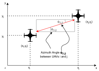
To introduce beamforming into the system, we consider each UAV to be equipped with an Uniform Planar antenna Array (UPA) of dimension , where antennas are spaced (horizontally) and (vertically) wavelengths from one another [17]. This allows each drone to communicate with other devices in the same altitude, as well as, with drones at different heights. As discussed above, due to the nature of the open environment, we assume that there is predominantly LoS communication. In this scenario, the UAVs can also apply beamforming to improve the Signal to Interference plus Noise Ratio (SINR) by increasing antenna gain. To determine the steering vector for beamforming, we need to determine the angular separation between the corresponding UAVs. Figure 1 shows the 2-D representation of the angular separation, i.e. azimuth angle, between the UAVs and for perfect knowledge of position and attitude. Since and are imperfect estimates, the angle between the estimated position of UAV with respect to of UAV is itself a random variable. In the following, we omit the time index for simplicity.
Hence, the steering vector is defined based on the estimated azimuth and elevation angles between the th and th UAVs, respectively, described by,
| (6) | ||||
| (7) |
where is the step function, equal to if and otherwise and and refers to the estimated yaw and pitch angles of the UAV. We can then compute the beamforming gain due to uncertainty in position information as a function of and :
| (8) |
where,
| (9) | ||||
| (10) |
where denotes the beamforming vector used for transmission/reception and
| (11) |
is the steering vector matrix associated to the azimuth () and elevation () angles. Also, note that, the azimuth for the UAV with respect to UAV is opposite of the angles of UAV with respect to UAV, i.e., these angles are supplementary due to the central controller devising the directions the UAVs have to orient themselves for transmission/reception. The same analogy is valid for the elevation angles between these UAVs. For simplicity, we have also defined as the wave vector for a planar wave impinging with angles and , is the wavelength and is the 3D spatial location of the th element of the antenna array. Specifically, for UPA, where we also consider the auxiliary functions and .
We can then compute the expected received power over link as:
| (12) |
The received power only depends on the transmission power , the beamforming gain for the transmission and reception, and the distance . Note that, the central controller devises the transmit and receive beamforming vector based on the estimated positions of the UAVs and thereby determines the expected received power at the receiver. By using the Shannon rate formula, we can then get the expected capacity under interference
| (13) |
where is the noise power spectral density and the bandwidth of the channel. Naturally, the distribution of this capacity is extremely complex, as it is a highly nonlinear function of the estimated positions and attitudes in the swarm. As such, it is extremely hard to estimate directly, but we can use a Monte Carlo sampling method to draw the real state of the swarm from the belief distribution, which can approximate the real distribution when given enough samples.
II-A Analog Beamforming Design
The design of the beamforming vectors and directly influences the behaviour of the power response . For a fixed transmitter to simultaneously communicate with multiple receivers, it is essential to design a beamforming that directs the emitted signal towards these receivers while keeping the interference from other receivers as low as possible. For instance, when the Channel State Information (CSI) of all receivers is perfectly known at the transmitter, one can design and as a zero-forcing beamformers [17]. This type of beamforming design is primarily applicable for traditional fixed-transmitter communication systems. Our scenario, however, differs in at least three aspects from this traditional scheme. Firstly, each UAV is only interested in communicating with a single receiver at a particular time based on the route devised by the routing protocol. Secondly, the control station does not have the current CSI for each of the UAVs. In fact, keeping track of all CSIs among the different UAVs in this scenario is a hard task due to high mobility of the UAVs. Finally and the most important characteristic of the scenario is the mobility of the transmitter. In our scenario, UAVs are mobile transmitters which can easily be rotated towards a desired direction. Thus, in our devised scenario, alignment happens by rotating pairs of UAVs towards each other.
Moreover, due to the characteristics mentioned above, designing and for our communication scheme boils down to choosing a narrow or wide beam. Notice that, in the former, a narrow beam potentially reduces the amount of interference leaked towards other UAVs, but requires knowledge over the true position . In contrast, designing a wide beam can compensate for the uncertainty over the desired location while potentially increasing interference among different UAVs. We simulate this behaviour by turning on/off the last rows or columns of the UPA of each UAV. To simulate this idea, let us consider the logical matrix with entries and dimension . We can design the beamforming vector by stacking the columns of matrix , i.e.,
| (14) |
where denotes the th column of the logical matrix. Then choosing a wide beam translates into setting the last rows/columns of the matrix to zero and the remaining entries to one. For instance, to have a omnidirectional transmission, it is sufficient to have a single active antenna [18]. Opposite to that, setting all entries of to one results in the narrow beam pattern. Using this idea we derive wider and narrower beams during our simulations. Moreover, we assume every transmitter to use the same beamformer over the entire route.
Finally, we also assume that there is no interference between the routes, that have common UAVs as their intermediate relays, by defining a simplified Time Division Multiple Access (TDMA) mechanism which divides the total time of communication equally among all different routes for the common UAV. This TDMA mechanism is defined by the control station, which knows all the concurrent routes in the network at a particular time.
III Position Uncertainty Based Beamformed Routing
Using the beamforming vectors defined in the previous section, we define the BA-SMURF protocol. In this protocol, the edge weight represents the average expected capacity of the link between UAVs and , denoted by . Hence, we design this routing problem as a standard maximum capacity route problem [19] over the graph , which can be solved by determining the maximum spanning tree using the link capacities, weighted by the source load, as a weighting metric for the graph edges. So, for a given beamformer, we apply a maximum spanning tree on the network graph to determine the route with maximum achievable capacity.
Hence, using (13), we devise the routes that maximize the minimum expected capacity. We assume that each UAV is occupied in transmitting or receiving cross-traffic for a fraction of the time i.e. , which must be subtracted to determine the available capacity of the link for UAV . As transmission is not full-duplex, we also assume that each node can spend at most half the time transmitting. So, the expected capacity of each link can be approximated by Monte Carlo sampling, and we can build a graph, knowing that the capacity of a route is given by:
| (15) |
The entire routing algorithm is devised at the central controller which tracks the positions of all the UAVs [13]. This, however, limits the beamforming adaptability over a single route, i.e., all the UAVs in the route follow the same beamforming pattern. In this work, the central controller devises the beamforming patterns for all the UAVs in the entire route based on the estimated position of the receiver UAV with respect to transmitter UAV, i.e., the central controllers designs the beamsteering vector shown in (11). In principle, it might seem sub-optimal to fix the beamforming pattern and only design the beamsteering vector (i.e., deploy analog beamforming), but to devise beamformed routes, the central controller needs to have a perfect instantaneous knowledge of the channel (i.e., deploy digital beamforming), which is difficult in the current scenario.
IV Results
| Simulation Parameter | Simulation Value |
|---|---|
| Map Size [m] | |
| Density of UAVs [UAVs/km3] | |
| UAV Position Model | Unscented Kalman Filter |
| Maximum Transmission Distance [m] | 100 |
| MIMO Antenna | Uniform Planar Array (UPA) |
| Antenna Configurations for the UAVs | |
| Transmission Power [W] | 1 |
| Number of Simulated Networks | 240 |
| Bandwidth (MHz) | 100 |
In order to numerically evaluate the effects of position uncertainty and beamforming in routing protocols, we deploy a Monte Carlo simulation in MATLAB where the protocols are evaluated over randomly generated networks. The simulation parameters for the system are described in Tab. I. The protocols evaluated in the Monte Carlo simulation are:
-
1.
DBR: A purely distance-based protocol, which does not consider positioning uncertainty;
-
2.
SMURF: our scheme from [14], limited to a single path, which considers positioning uncertainty but does not include beamforming in the probability calculation;
-
3.
BA-SMURF: the proposed scheme, which takes into account the position uncertainty and beamforming.
These protocols are evaluated for both the ideal and tracked position. We indicate the former by attaching “-I” to the end of the respective protocol name, and the latter by attaching “-T’. Moreover, the tracked position information is obtained from the output of the Kalman filter at the central controller. Hence, the performance of the protocols evaluated in this scenario is the performance achieved based on the available tracked information of the UAVs. By taking into account the true position of the UAVs, we can determine the ideal performance of the protocol, which represents an upper bound to the practically achievable performance. Additionally, each UAV is equipped with the same UPA antenna configuration and is able to communicate with other drones using the beamforming design defined in the previous section.
To accurately determine the performance achieved for all the protocols, we carry out simulations with different antenna configurations and different densities. Figure 2 compares the average throughput of all the protocols applied in a network with density of UAVs/km3 (which corresponds to about 20 drones in network) and for the antenna configuration of , i.e., elements in the antenna. Firstly, it is easy to see that the most important factor is the availability of the true position: the real protocols, which operate on uncertain information, have a throughput that is lower by about 10% than the one obtained by their respective ideal versions. However, BA-SMURF outperforms both SMURF and DBR for both true and tracked positions. This indicates that the routes chosen by BA-SMURF are able to provide median as well as the worst case throughput (i.e., percentile) higher than SMURF and DBR for both tracked and true scenarios. Hence, BA-SMURF is able to outperform the other two protocols by about 5% even with a static beamforming scheme.
A similar behavior is observed when comparing all the protocols considering different UAV densities. Considering the same antenna configuration as above, Figure 3 illustrates this density comparison. Both SMURF and the enhanced BA-SMURF version can exploit high-density network to find better routes, i.e., routes with high link existence probability (for SMURF) and high minimum expected capacity (for BA-SMURF). On the other hand, DBR’s throughput does not increase with increasing density, as the protocol only takes into account the distance between the tracked positions, without considering the uncertainty: consequently, it will not choose safer routes, which are available if the density of the network increases. It is also evident from the figure that BA-SMURF outperforms both SMURF and DBR for all densities and for both the tracked and true position information, thanks to its joint consideration of the position uncertainty and beamforming pattern. Additionally, considering the beamforming design can allow the system to potentially reduce interference to other established routes, as well as allowing for more efficient power allocation for the transmission towards the receiver UAV.
Another interesting evaluation is the impact of different antenna configurations, i.e., different beamforming patterns, assuming a fixed power allocation for the antenna. Figure 4 shows the performance achieved by all the protocols for different antenna configurations in a network with a density of UAVs/km3. The performance of the protocols when taking into account true positions of the UAVs in the network is similar for all different antenna configurations. This shows that beamforming does not impact the performance when the true positions are known by the protocols, as the transmitter UAV is able to beamform the signal in the correct direction. However, when considering the tracked position information, beamforming becomes a problem: as the number of elements in the antenna increases, the transmitted beam narrows, leading to a stronger impact of the position uncertainty, and consequently, to a lower throughput. The loss in performance is due to the fact that the central controller does not know the true position of the UAVs and it devises the beamsteering vector based on the expected position of the UAVs: the narrower the beam gets, the larger the impact of pointing errors becomes. When the number of elements is 1, the performance of all the protocols is similar for tracked and true position information, since the antenna is omnidirectional. Additionally, BA-SMURF outperforms SMURF and DBR both when considering perfect information for the protocols and in the more realistic setting for all the antenna configurations. This highlights the importance of incorporating beamforming information to determine routes in FANETs.
While the average throughput for the considered route is higher when choosing a single antenna element (i.e., an omnidirectional antenna), the downside of this configuration is the high interference to neighboring UAVs, as shown in Figure 5: an omnidirectional transmission will have an increased impact on other transmissions. When the network is interference-limited, the use of narrow beamforming design to reduce the neighbourhood interference is beneficial: the lower received power due to pointing errors is compensated by the lower interference. On the other hand, when the network is noise-limited, the use of wide beamforming is beneficial, as it can reduce the impact of UAV positioning uncertainty. Our results also show that the need for adaptive beamforming for each UAV is crucial, as having the same beamforming design for the entire network can reduce the overall performance achieved by the network.
V Conclusion
In this work, we provide a statistical analysis of a FANET with tracked position information and beamforming design, and derive the minimum expected capacity for both single links and entire routes. We then present the BA-SMURF protocol, a multihop routing protocol, which computes the route with the highest expected capacity. The simulation results show that BA-SMURF can outperform the existing protocols in realistic network conditions. It is also shown to outperform state of the art approaches for different UAV network densities and different antenna configurations.
Moving forward, an interesting avenue of future research is to define beamforming optimization scenarios with respect to the tracking information available for each UAV in the networks, jointly optimizing them and the routing process based on the UAVs’ tracked positions and the estimation uncertainty.
References
- [1] L. F. Gonzalez, G. A. Montes, E. Puig, S. Johnson, K. Mengersen, and K. J. Gaston, “Unmanned Aerial Vehicles (UAVs) and artificial intelligence revolutionizing wildlife monitoring and conservation,” Sensors, vol. 16, no. 1, p. 97, Jan 2016.
- [2] M. A. Ma’Sum, M. K. Arrofi, G. Jati, F. Arifin, M. N. Kurniawan, P. Mursanto, and W. Jatmiko, “Simulation of intelligent unmanned aerial vehicle (UAV) for military surveillance,” in International Conference on Advanced Computer Science and Information Systems (ICACSIS). IEEE, Mar 2013, pp. 161–166.
- [3] B. Ji, Y. Li, B. Zhou, C. Li, K. Song, and H. Wen, “Performance analysis of UAV relay assisted IoT communication network enhanced with energy harvesting,” IEEE Access, vol. 7, pp. 38 738–38 747, 2019.
- [4] Y. Wan, K. Namuduri, Y. Zhou, and S. Fu, “A smooth-turn mobility model for airborne networks,” IEEE Transactions on Vehicular Technology, vol. 62, no. 7, pp. 3359–3370, Mar 2013.
- [5] J.-D. M. M. Biomo, T. Kunz, and M. St-Hilaire, “An enhanced Gauss-Markov mobility model for simulations of unmanned aerial ad hoc networks,” in 7th IFIP Wireless and Mobile Networking Conference (WMNC). IEEE, May 2014, pp. 1–8.
- [6] M. O. Farooq, “Multi-hop communication protocol for LoRa with software-defined networking extension,” Internet of Things, vol. 14, p. 100379, 2021.
- [7] Z. Zhao, P. Cumino, A. Souza, D. Rosario, T. Braun, E. Cerqueira, and M. Gerla, “Software-defined unmanned aerial vehicles networking for video dissemination services,” Ad Hoc Networks, vol. 83, pp. 68–77, Feb. 2019.
- [8] C. J. Katila, A. Di Gianni, C. Buratti, and R. Verdone, “Routing protocols for video surveillance drones in IEEE 802.11s wireless mesh networks,” in European Conference on Networks and Communications (EuCNC). IEEE, Jun 2017, pp. 1–5.
- [9] N. E. H. Bahloul, S. Boudjit, M. Abdennebi, and D. E. Boubiche, “A flocking-based on demand routing protocol for Unmanned Aerial Vehicles,” Journal of Computer Science and Technology, vol. 33, no. 2, pp. 263–276, Mar 2018.
- [10] M. Song, J. Liu, and S. Yang, “A mobility prediction and delay prediction routing protocol for UAV networks,” in 10th International Conference on Wireless Communications and Signal Processing (WCSP). IEEE, Oct 2018, pp. 1–6.
- [11] P. Xie, “An enhanced OLSR routing protocol based on node link expiration time and residual energy in ocean FANETs,” in 24th Asia-Pacific Conference on Communications (APCC). IEEE, Nov 2018, pp. 598–603.
- [12] S. N. Pari and D. Gangadaran, “A reliable prognostic communication routing for flying ad hoc networks,” in 2nd International Conference on Trends in Electronics and Informatics (ICOEI). IEEE, May 2018, pp. 33–38.
- [13] F. Mason, F. Chiariotti, M. Capuzzo, D. Magrin, A. Zanella, and M. Zorzi, “Combining LoRaWAN and a New 3D Motion Model for Remote UAV Tracking,” in IEEE INFOCOM Wireless Sensor, Robot and UAV Networks (WiSARN) Workshop, Jul 2020. [Online]. Available: https://arxiv.org/abs/2002.04849
- [14] A. A. Deshpande, F. Chiariotti, and A. Zanella, “SMURF: Reliable Multipath Routing in Flying Ad-Hoc Networks,” in 2020 Mediterranean Communication and Computer Networking Conference (MedComNet). IEEE, 2020, pp. 1–8.
- [15] A. Al-Hourani, “On the probability of Line-of-Sight in urban environments,” IEEE Wireless Communications Letters, vol. 9, no. 8, pp. 1178–1181, 2020.
- [16] F. Noor, M. A. Khan, A. Al-Zahrani, I. Ullah, and K. A. Al-Dhlan, “A Review on Communications Perspective of Flying Ad-Hoc Networks: Key Enabling Wireless Technologies, Applications, Challenges and Open Research Topics,” Drones, vol. 4, no. 4, p. 65, 2020.
- [17] E. Björnson, J. Hoydis, and L. Sanguinetti, “Massive MIMO networks: Spectral, energy, and hardware efficiency,” Foundations and Trends in Signal Processing, vol. 11, no. 3-4, pp. 154–655, 2017.
- [18] D. Qiao, H. Qian, and G. Y. Li, “Broadbeam for massive MIMO systems,” IEEE Transactions on Signal Processing, vol. 64, no. 9, pp. 2365–2374, 2016.
- [19] T. Hu, “The maximum capacity route problem,” Operations Research, vol. 9, no. 6, pp. 898–900, Dec. 1961.