Atomistic Modelling of Energy Dissipation in Nanoscale Gears
Abstract
Molecule- and solid-state gears build the elementary constituents of nanoscale mechanical machineries. Recent experimental advances in fabrication technologies in the field have strongly contributed to better delineate the roadmap towards the ultimate goal of engineering molecular-scale mechanical devices. To complement experimental studies, computer simulations play an invaluable role, since they allow to address, with atomistic resolution, various fundamental issues such as the transmission of angular momentum in nanoscale gear trains and the mechanisms of energy dissipation at such length scales. We review in this chapter our work addressing the latter problem. Our computational approach is based on classical atomistic Molecular Dynamics simulations. Two basic problems are discussed: (i) the dominant energy dissipation channels of a rotating solid-state nanogear adsorbed on a surface, and (ii) the transmission of rotational motion and frictional processes in a heterogeneous gear pair consisting of a graphene nanodisk and a molecular-scale gear.
Keywords: classical Molecular Dynamics, molecule gears, solid-state gears, friction, dissipation
1 Introduction
The increasing demands on the miniaturization of digital and analog devices has led to a proliferation of studies aiming at designing efficient strategies to reduce physical dimensions of the device’s building blocks while still preserving their basic functionalities. While such approaches have been extensively developed and refined in the domain of electronic devices following both top-down and bottom-up strategies less work has been invested in the investigation of truly nanoscale mechanical systems with basic components consisting of molecularJuYun2007 ; Yang2014 ; Mailly2020 or solid-state nanogearsJoachim2020 . The most recent advances in fabrication techniques in this field, including bottom-up approachesGisbert2019 ; Soong2000 as well as top-down methods such as focused ion beamsJuYun2007 or electron beamsDeng2011 ; Yang2014 point, however, in a very promising direction. In this context, there are several general issues, which play an important role in determining the feasibility of a roadmap leading to the fabrication of nanoscale analog devices based on gear trains: (1) the capability of transmitting angular momentum along gear trains, (2) the energy dissipation mechanisms from gear systems into the environment, (3) the atomistic features of the interface between solid-state nanogears and molecule gears, (4) the possible improvement of angular momentum transmission in nanoscale gear trains mediated by lubricants, and (5) the triggering of a rotation at the level of single molecule gears.
In this Chapter we will focus on different aspects related to items (2) and (3) using representative nanogear systems. Studies related to item (1) in molecule gear trains have been previously presented in e.g. Lin2020 ; PhysRevApplied.13.034024 ; Hove2018a ; Chen2018 ; Hove2018 . The influence of lubricants in nanoscale solid-state gears has been recently studied in lin2021effect ; doi:10.1021/acs.jpcc.1c04239 . Work related to item (5) is, on the contrary, scarce, see e.g. Refs. PES ; Lin2019 .
Concerning item (2), it is well-established that the friction laws known from macroscopic systems cannot, in general, be extrapolated to nanoscale systemsVanossi2013 ; Gnecco2006 ; Perssson1995 ; Wen2017 ; Manini2016 ; Sankar2020 , and this has lead to a large number of experimentalLodge2016 ; Smith1996 ; Walker2012 ; Binnig1987 ; Balakrishna2014 and model-basedTomlinson1929 ; Borner ; Panizon2018 ; Guerra2010 investigations. In general terms, two qualitatively different friction regimes have been identified, which depend on the center-of-mass velocity: (a) a low-speed, stochastic regime ( 1000 cm/s)Tomassone1997a , where the system is close to thermal equilibrium and friction is governed by Brownian motion, (b) a high-speed, viscous regimeTomassone1997a ; Guerra2010 , where the system is out of equilibrium and friction is proportional to the number of collisions with surface corrugations per unit timeGuerra2010 . However, in the case of rotational motion, it is not immediately obvious if a clear separation of stochastic and viscous regimes is possible, since high tangential velocity (outer) and low tangential velocity (inner) atoms in a nanoscale gear are present at the same time and the motion of both sets is correlated. Additionally, for molecule gears as well as nanoscale solid-state gears, energy dissipation into internal degrees of freedom due to the larger conformational flexibility of the gears (compared with their macroscopic counterparts) can play a non-negligible role. For the development of truly nanoscale mechanical machines it is also of interest to address not only the transmission of rotational motion between gears of the same type (either solid-state or molecule gears), but also the interaction of gears with different sizes and different materials (item (3) above). A typical situation would be that of a solid-state nanogear coupled to a molecule gear. The transmission of rotational motion in such a situation is by far not obvious: molecule gears are rather flexible and energy can be dissipated into internal degrees of freedom. Moreover, the contact interface of both gears will have atomic resolution and, therefore, may require a very careful design to ensure good interlocking. Still, recent progress in the miniaturization of solid states gears down to the nanoscaleJuYun2007 ; Yang2014 ; Mailly2020 ; Deng2011 is calling for the study of gear trains and of the transfer of rotation over different length scales. We may have been thus reaching the experimental stage where a single molecule gear (with diameter 1 nm)Manzano2009 can be rotated by a solid state nanogear (diameter 10 nm)Yang2014 ; Mailly2020 . Rotation of single molecule gearsChiaravalloti2007 ; Moresco2015 ; Mishra2015 ; Perera2013 ; Manzano2009 or short molecule gear trainsAuYeung2020 ; WeiHyo2019 ; Zhang2016 has already been experimentally demonstrated. Building nanoscale devices where the transmission of angular momentum across gears with different sizes becomes feasible, poses many challenges to the experimentalistJoachim2020 : achieving gear thickness compatibility, the surface preservation with atomistic resolution after transferring the solid state nanogear on it, the mechanical stability of the rotational axle, and last but not least the triggering of the rotational motion and its transmission to gears of different size and composition.
This chapter is organized as follows: in Sec. 2, we describe briefly the basic Molecular Dynamics simulation details for the three different model systems we are going to discuss in Sec. 3. The latter includes, whenever necessary, more specific information on the simulation details. In Subsec. 3.1, we study the energy dissipation mechanism in a setup consisting of a nanoscale solid-state gear adsorbed on different substrates. In Subsec. 3.2 the rotational transmission between a graphene nanodisk and a molecule gear deposited on a Cu surface is addressed, together with an estimate of the vibrational and electronic contributions to rotational friction. The chapter ends with a summary of the results and an outlook in Sec. 4.
2 Simulation methodology
For all the simulations presented here we have used the Large-scale Atomic/Molecular Massively Parallel Simulator (LAMMPS) softwarePlimpton1995 . The choice of the corresponding classical force fields is, however, dependent on the specific system setup and is briefly described in the following:
-
1.
For the solid-state diamond gear on SiO2 substrates (Sec. 3.1), we use the Tersoff potential Tersoff1988 in the SiO2 bulk, whereas the adaptive intermolecular reactive empirical bond order (AIREBO) potential Stuart2013 was chosen for the carbon subsystem (gear). The coupling between both subsystems was assumed to be a non-bonding 12-6 Lennard-Jones type of potential. The corresponding parameters are given in Ref. Lin2020a . When using a graphene substrate for comparison, the AIREBO potential was also used for the surface.
-
2.
The interaction between a graphene nanodisk and a molecule gear on a Cu substrate ((Sec. 3.2) was treated via the Reactive Force Field (ReaxFF)Plimpton1995 . The upper two Cu layers were coupled to a Nosé–Hoover thermostatNose1984 ; Hoover1985 to fix a generic temperature = 10K, which is of similar order as that from low-temperature STM experiments. To define corresponding collective rotational variables out of the gear atomistic conformations we exploited the nearly rigid-body approximation (NRBA), see Refs. Lin2019a ; Lin2020 for technical details.
3 Results
3.1 Diamond solid-state gear on substrates
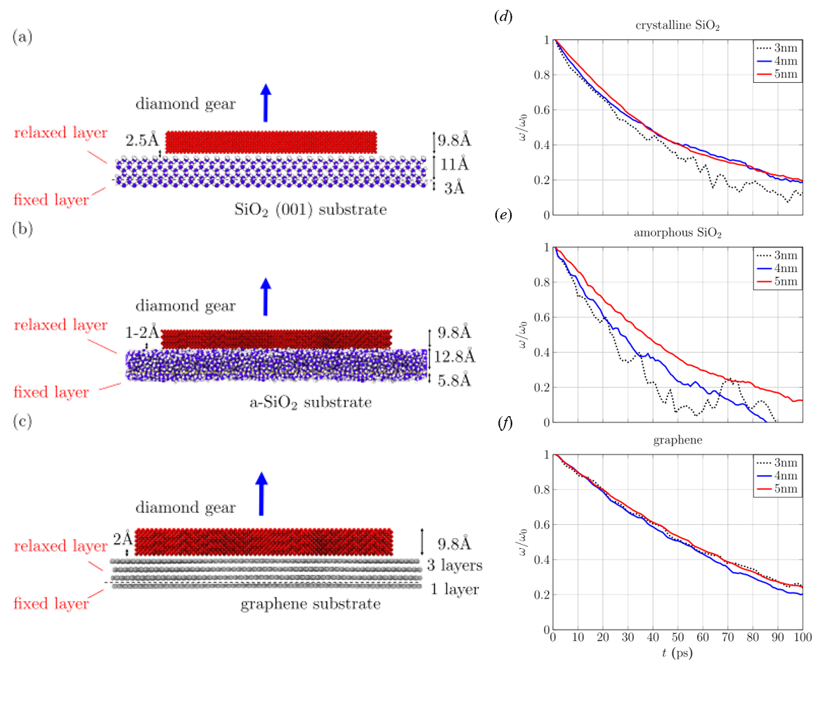
In this section we will investigate a solid-state diamond nanogear physisorbed on different substrates. Our aim is to elucidate the dependence of the energy dissipation via friction on the type of substrate. Using classical MD simulations allow us to reach the relevant time scales in the range of ps up to ns Persson1996 . In the first case, we consider a system consisting of a diamond-based solid state gear (radius nm and thickness Å) with involute profileNorton2010 on top of an -cristobalite SiO2(001) surface. The size of the substrate is 23.0 nm15.3 nm1.39 nm and we use periodic boundary conditions in and directions. The initial vertical separation between gear and substrate is 2.5Å and, for preventing lateral and vertical motion the bottom layer of the substrate was fixed while the remaining part was allowed to structurally relax. For the sake of comparison, we have also used two additional substrates: amorphous SiO2 and graphene.
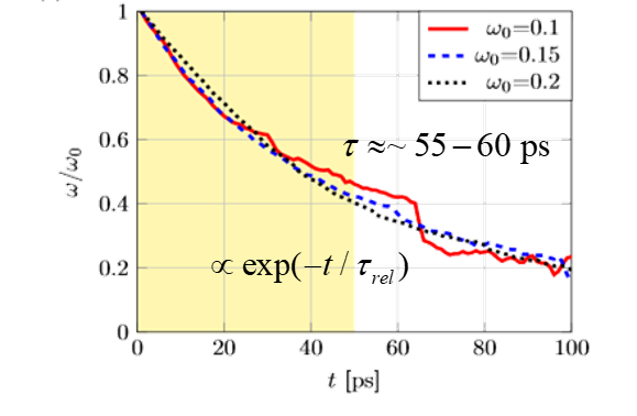
Viscous dissipation limit. We first address the typical time scales associated with the friction process. Taking into account that the atoms within a rotating gear have large tangential velocities, it is reasonable to expect that we are in the same frictional regime as for linear friction with high translation velocityGuerra2010 . Therefore, ignoring any applied external torque, the gear dynamics in the high friction limit will be described by a first order differential equation for the angular velocity :
| (1) |
where is the damping coefficient and is the gear moment of inertia. From this equation we immediately obtain an exponential decay of the velocity with relaxation time given by . In the frame of our MD simulations, we give an initial angular velocity to the gear and monitor its decay in time, expecting to find the exponential behavior obtained from Eq. (1), which in this case would result from the van-der-Waals interactions between the gear and the substrate at a given temperature. The results are displayed in Fig. 1 for different initial angular velocities , and rad/ps and for an MD run of ps. Notice that in the figure, we have plotted scaled with the corresponding value of . It becomes apparent that the relaxation process does not sensitively depend on and it displays (up to small fluctuations for small initial angular velocity) the expected exponential decay as a function of time. Fitting the obtained curves in the interval from to ps (highlighted in yellow in the figure) to a single exponential allows to obtain the corresponding relaxation times , and ps for , and rad/ps, respectively. Another interesting result is that for the used gear radius of 5 nm the dynamics is that of a deterministic rotor rather than a Brownian rotor, since stochastic fluctuations are increasingly suppressed with increasing gear size.
Substrate dependence of the angular velocity relaxation. To better understand the influence of a specific substrate on the relaxation process, we carried out MD simulations over ps at K with initial angular velocity rad/ps on three different substrates: crystalline SiO2, amorphous SiO2, and graphene, see Fig. 2 (a)-(c). Besides the different substrates, we have also considered gears with three different diameters: 3,4, and 5 nm. The results showing the relaxation of the angular velocity for different substrates and gear sizes are shown in Figs. 2 (d), (e), and (f). It becomes clear from the figures that decreasing the gear radius leads in general to an increase of the angular velocity fluctuations, especially for -cristobalite and amorphous SiO2, although the effect is less pronounced for the graphene substrate. The origin of this behavior is that a reduction in gear size implies a reduction of the rotational kinetic energy, so that the gear will be more sensitive to surface vibrations, entering the low average tangential velocity dissipation regime where Brownian behavior becomes dominant. A further analysis of the relaxation times Lin2020a shows that for crystalline SiO2 (and even more for graphene) is approximately gear-size independent, while for amorphous SiO2 becomes smaller with decreasing gear size. This behavior is related to the decreasing degree of surface corrugation when going from amorphous SiO2 to crystalline SiO2 and to graphene.
Scrutinizing surface phonon excitations. Although part of the rotational kinetic energy is dissipated into internal degrees of freedom of the gearLin2020a , the major dissipation channel is related to the excitation of surface vibrations. It is, therefore, interesting to see how the energy dissipation is modified when the thickness of the relaxed layer is changed (note that the overall thickness of the substrate in the simulations is always the same, only the thickness of the fixed layer is varied). The results for the crystalline SiO2 substrate are shown in Fig. 3 (a). One can see that with increasing the angular velocity relaxation time becomes shorter (i.e., faster exponential decay). However, for larger there is a tendency of the decay rate to saturate.
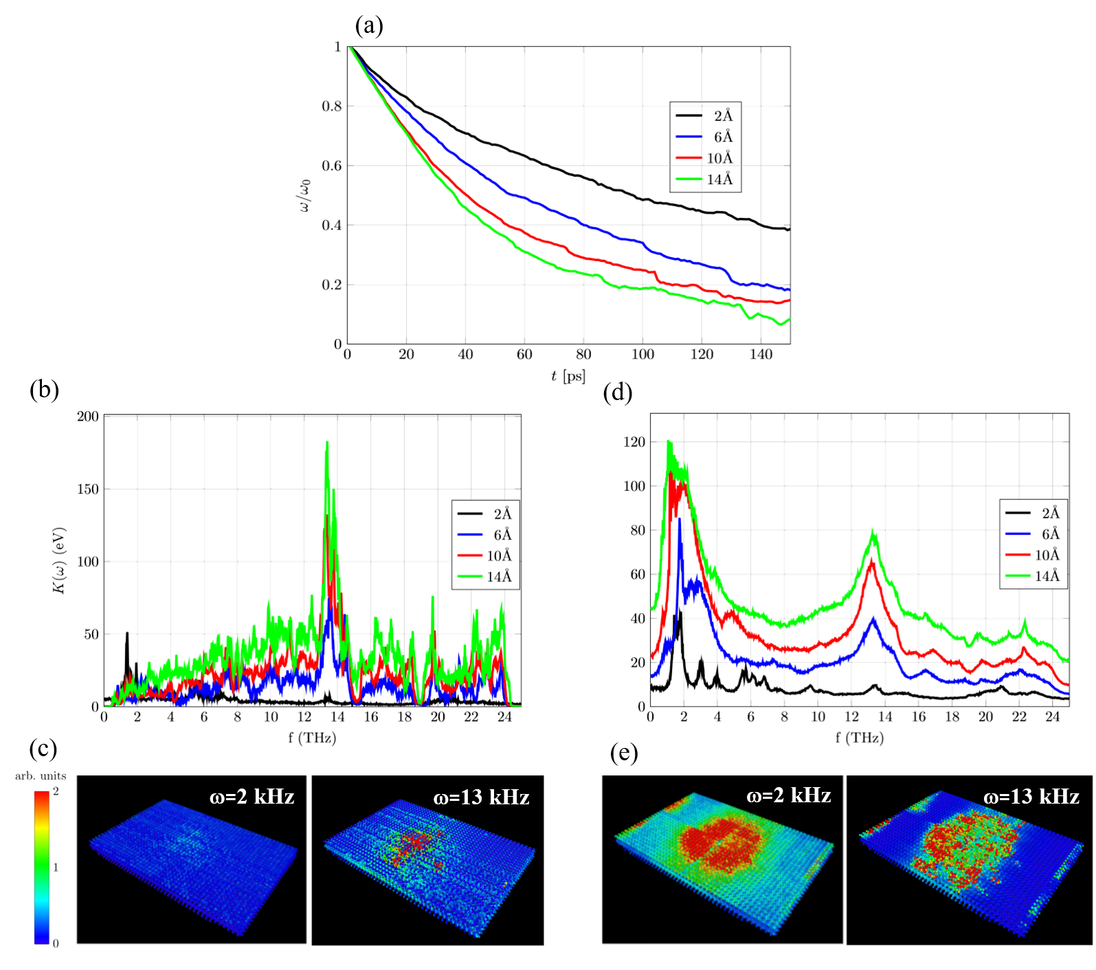
A deeper understanding of the energy dissipation process can be gained by analyzing the kinetic energy spectrum Meshkov1997 ; Lee1993 as given by:
| (2) |
with being the Fourier transform of the velocity of the atom in the relaxed layer (R) and is the frequency. To identify the features arising purely from rotational dissipation, we show in Figs. 3 (b) and (d) the kinetic energy spectra for the cases without and with gear rotation, respectively. For the case without rotation, Fig. 3 (b), as increases a prominent spectral feature around THz emerges, which is related to the well-known van-Hove singularity in the phonon density of states of crystalline SiO2Wehinger2015 .
When the gear rotational motion is allowed, then two main features can be observed in the kinetic energy spectral function, see Fig. 3 (e). First of all, the spectral feature at THz gets strongly broadened (its lifetime is shorter) and loses intensity with decreasing . This latter effect indicates that this peak is a bulk property rather than a surface property. The former effect hints at the increased energy dissipation into the substrate via phonon excitation. Secondly, a new spectral feature appears at THz. The corresponding peak intensity increases with increasing , but the trend weakens for Å, suggesting that only surface phonons are excited.
The bottom panels Fig. 3 (c) and Fig. 3 (d) provide a visualization of the spatial distribution of the two previously discussed spectral features at THz and THz. The calculation has been done by applying a band filter to the kinetic energy spectrum with bandwidth THz Lin2020a .
Fig. 3 (c) shows that without gear rotation more atoms are excited at THz than at THz, which is consistent with the features found in the kinetic energy spectrum. In contrast, upon allowing for gear rotation (Fig. 3 (e)) the mode at THz has been strongly excited and localizes below the gear (the red region around the center), but also for THz, there is also a visible pattern, which is apparently due to the gear rotation. The conclusion from this analysis is that the low-frequency excitation is largely related to surface phonon modes excited by the gear rotation.
3.2 Graphene nanodisk-molecule gear interaction
As discussed in the Introduction, another interesting problem for the development and down scaling of gear systems is the possibility to couple gears with quite different sizes and to explore the efficiency of rotational transmission and energy dissipation. We have therefore studied in lin2021nanographene a model system consisting of a graphene nanodisk and a single molecule gear, both adsorbed on a Cu(111) surface, see Fig. 6 a). The molecule gear is a hexa-tert -butylphenylbenzene (HB-BPB) molecule with 6 tert-butylphenyl teeth. Further structural details as well as the rationale for choosing this molecule gear are provided in the next paragraphs.
In what follows, we will use a simple way to characterize the mechanical transmission of rotational motion between two gears by defining a locking coefficient asLin2020 :
| (3) |
where is the average angular velocity of gear and is the terminal angular velocity of a rigid-body corresponding to this gear. For perfectly interlocked rigid gears, the coefficients must be equal to unity. For soft gears or imperfect transmission, will in general be much smaller than unity, since there will be dissipation into internal degrees of freedom.
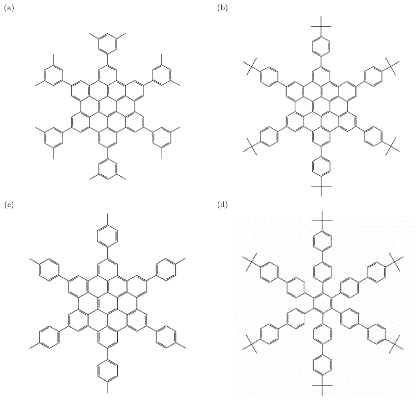
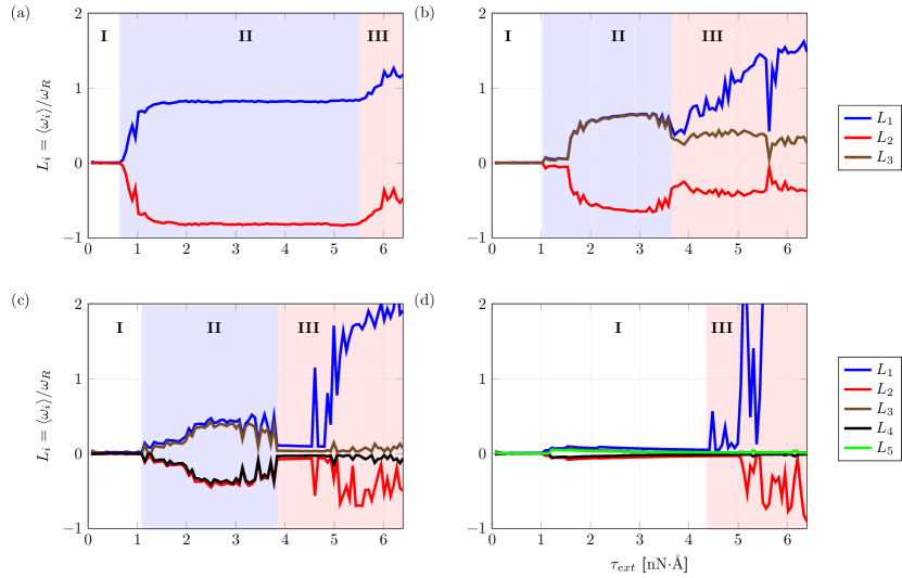
Which molecule gear? Our choice of the molecule gear has been based on the test of few similar candidates and on their capability to efficiently transfer angular momentum in a molecule gear pair. In Fig. 4 we show these molecules, which differ both in the compactness of their cores (alkyl groups or coronene cores) as well as on the shape of the teeth (adding one more phenyl ring).
To characterize the rotational transmission of the molecule gears we use the previously defined locking coefficient, Eq. (3), and plot it as a function of an external torque applied on the first gear. As previously shown in Ref. Lin2020 for molecule gears, three different regimes can be identified (which do not necessarily appear simultaneously in each case), depending on the strength of the applied torque: (I) underdriving regime for which , i.e. the average angular velocities for both gears nearly vanish and there is no rotation; (II) driving regime with , where transmission of rotation between the two gears takes place; (III) overdriving regime with , where the driven gear cannot follow the driver. The goal is, therefore, to design a molecule gear where the driving regime is dominant over a broad range of applied torques. The corresponding phase diagrams for the four molecules (a) to (d) of Fig. 4 are shown in Fig. 5.
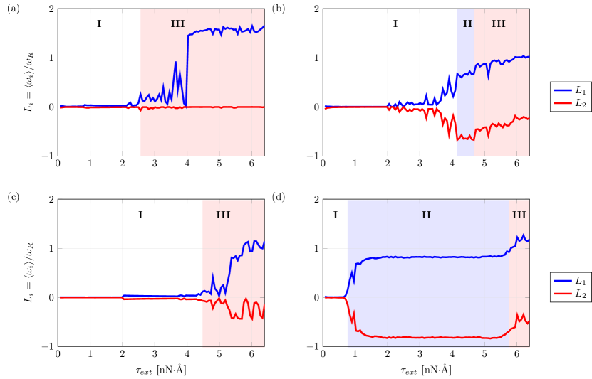
For molecule (a), the distance between gears is nm and only phases I and III were identified, so that no collective rotations take place. For molecule (b), the distance is nm, and now all three phases appear, meaning that collective rotations are possible. For the molecule (c), nm and we have again only regions I and III. Note that in the red region one can still see nonzero values for but the magnitude is relatively small compared with . This implies that collective rotations are possible, but relative sliding between gears can happen as well. For molecule (d), nm and one can immediately see that there is a wider region II compared to the other molecule gears, which means collective rotations are robust in terms of external torque. This is why we have chosen case (d), the hexa-tert-butylbiphenylbenzene (HB-BPB) molecule, as our candidate to interface with the graphene nanodisk.
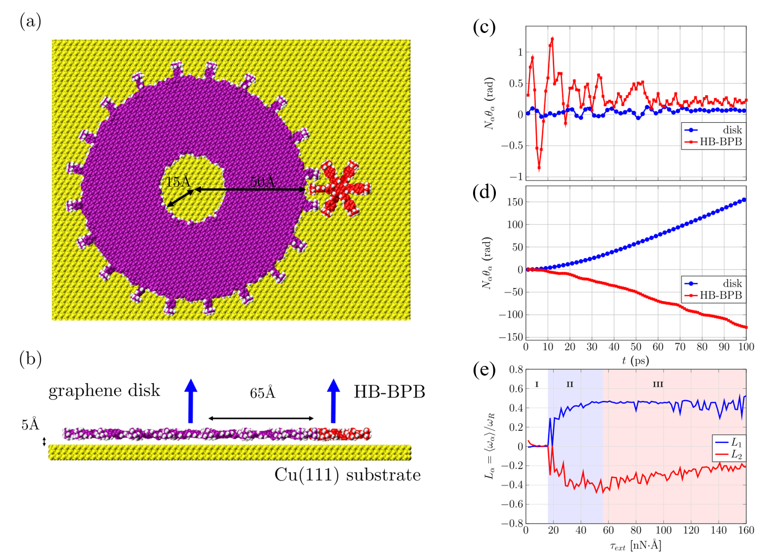
Heterogeneous gears: graphene nanodisk-molecule gear. After the previous discussion for choosing an appropriate molecule gear, we address now the heterogeneous system made of a graphene disk with a diameter of 10 nm and a hexa-tert -butylphenylbenzene (HB-BPB) molecule with six tert-butylphenyl teeth. For the graphene nanodisk we tested different edge profiles such as irregular edges (roughness), involute shape, and tert-butylphenyl teeth. Only in the latter case a correlated rotation of both gears for clockwise and anti-clockwise directions of rotation was obtained. Therefore, this is the atomistic model chosen for the following simulations. We remark that the thickness of the graphene nanodisk is compatible with the molecule gear chemical structure and with its physisorption height on the used Cu(111) surface. We have further found that using 20 tert-butylpheny chemical groups provides an optimal number of teeth to ensure a smooth transmission of rotational motion. Other master diameters will certainly require to adapt again its edge chemical structure. There is also a central 1.5 nm hole in the master Fig. 6 (a) representing the location of the rotational axle, which is not explicitly modelled in this study. The optimized center-of-mass separation between the master (graphene disk) and the HB-BPB molecule gear was found to be 6.5 nm.
We now apply an external torque on the master and monitor the angular momentum transfer to the HB-BPB molecule. The time dependence of the product for a small nNÅ and an intermediate nNÅ torques are presented in Fig. 6 (c) and (d, respectively, with and . For a small torque only small amplitude oscillations of both gears around their equilibrium conformations are found, since is not large enough to overcome the surface friction of the master on the substrate and to allow the molecule gear to overcome the energy barrier of the potential energy surface on Cu(111) at the simulation temperature of = 10 K. For intermediate , on the contrary, perfectly interlocked rotation is obtained, which satisfies the classical condition MacKinnon2002 . In Fig. 6 (e) we plot the locking coefficient as a function of the applied torque using with kgms-1 (extracted from in the same MD simulation) being the damping coefficient corresponding to a rigid disk on the Cu surface. For , we then obtain . Interestingly, also for this heterogeneous two-gear system, we can still identify three typical different regimes (highlighted with different colors). In the (white) region I ( nNÅ) the average angular velocities for both gears nearly vanish, and there is no rotation (underdriving regime). In the (blue) region II ( nNÅ) transmission of rotation between the two gears takes place (driving regime). Finally, in the (red) region III ( nNÅ) the molecule gear cannot follow the master rotation (overdriving regime). Therefore, there is a relevant window in the applied torque (driving regime) where the interlocking of the two gears is largely favoured and the rotational transmission is optimal.
Nanodisk-molecule gear: Phononic dissipation channel. In the previously described situation the main source of energy dissipation (friction), which requires the application of a large torque, is the interaction between the master and the Cu(111) surface. To address in more detail this issue, we have considered graphene nanodisks with different diameters adsorbed on the Cu(111) surface, but without including the molecule gear. Then, by applying an initial angular velocity we allow the graphene disk to slow down and eventually stop its rotation as a result of frictional dissipation to the substrate. The estimated tangential velocities indicate that the system is in the viscous dissipation regimeGuerra2010 . Hence, by plotting the time-dependent angular velocity as a function of simulation time for the different diameters, we can fit each curve to a single exponential function and can extract the corresponding relaxation times. The function is shown in Fig. 7 (a). As it may be expected, the relaxation time is longer for small diameters than for larger diameters as a result of the increased contact area with the surface.
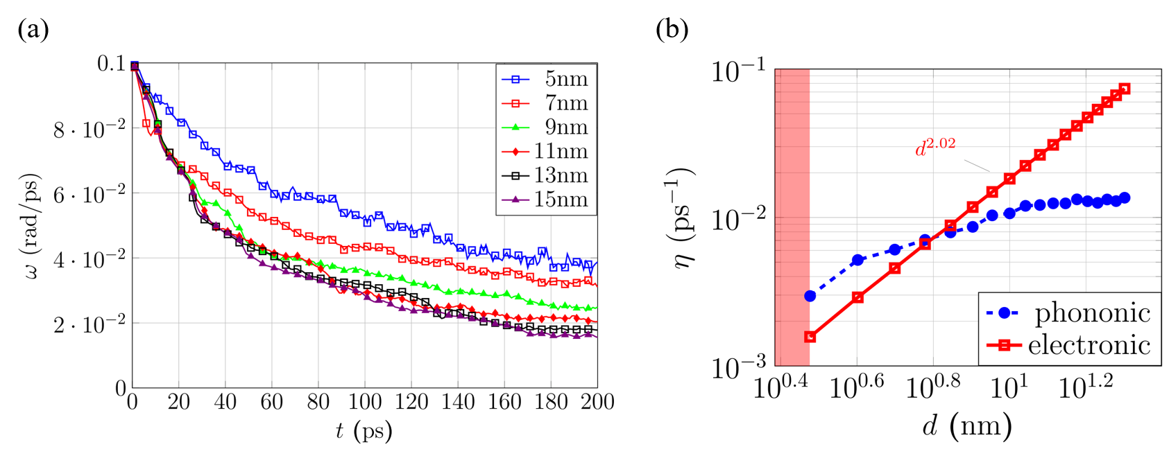
The obtained inverse relaxation times , related to the friction coefficient , are now displayed as a function of the nanodisk diameter as the blue curve in Fig. 7 (b). As seen in the figure, the friction increases with increasing diameter, but it becomes weakly dependent on for values larger than 10 nm. Notice also that for nm (highlighted by the vertical window in light red in Fig. 7 (b)), the nanodisks no longer rotate but oscillate in a Brownian like motion. The reason for this transition is that the potential energy barrier height for rotation becomes in this domain larger that the initially imposed rotational kinetic energy, so that only fluctuations around equilibrium positions are feasible.
Nanodisk-molecule gear: Electronic dissipation channel. Although our classical MD simulations do not allow to directly address dissipation processes involving the electronic system, we can try to obtain estimates of it by using mathematical relations available from quantum mechanical studies of model systems. In the case of van der Waals related electronic friction, estimates from second-order perturbation theory using a Jellium model were obtained in Refs.Persson2000 ; Persson1995 :
| (4) |
Here, is the elementary charge, is the reduced Planck constant, the Bohr radius, the static polarizability of the adsorbate, the plasma frequency of the metallic substrate, the Fermi wave vector, the Fermi frequency, the electron mass, the mass of the graphene nanodisk and is the parallel frictional integral as a function of the electron gas radius and the distance between the graphene nanodisk and the substrate ( Å in our case). For Cu(111), rad/s Ordal1985 , rad/s Ashcroft1976 , A-1 Ashcroft1976 and Persson2000 ( for Cu). For a monolayer graphene sheet, Å3 per unit cellKumar2016 . To estimate for a graphene nanodisk, we assume that this disk is large enough such that (one unit cell contains two carbon atoms) where is the number of carbon atoms in the graphene nanodisk. Using these parameter values, we can estimate the electronic contribution to the frictional process as a function of the nanodisk diameter. This is shown as the dark red curve in Fig. 7 (b). According to Eq. (4), the electronic friction coefficient is roughly proportional to since the increase of polarizability is proportional to the number of carbon atoms and it grows faster than the increase of the mass of a graphene nanodisk (). As it becomes clear from the figure, the electronic contribution to friction is dominant for larger disks whereas for smaller diameters the phononic dissipation channel dominates the process. As a consequence, a large (saturating phononic dissipation) graphene nanodisk of higher polarizability together with a substrate below the critical superconducting transition temperature (for suppressing the electronic dissipation channel) could provide an efficient starting setup where to build our modelled heterogeneous gear system.
Molecule gear trains based on HB-BPB: How efficient is the transmission of rotational motion? The graphene nanodisk-molecule gear system can be considered to form the driving part of a molecule gear train with additional HB-BPB molecules. It is therefore of interest to look closely at the critical inter-gear separations in order to optimize the rotational transmission. In Fig. 8, we show the corresponding locking coefficients of two HB-BPB gears (see also the scheme in Fig. 8 (f)) for different center-of-mass separations (a) nm, (b) nm, (c) nm, (d) nm and (e) nm, respectively. One can see that gears with nm give the optimal result for rotational transmission, since there is a wide range of applied torques corresponding to a driving phase (region II). This is also the separation used in Fig. 5. For nm, on the contrary, the driving region II is already considerably narrowed. For nm, there is largely only overdriving phase.
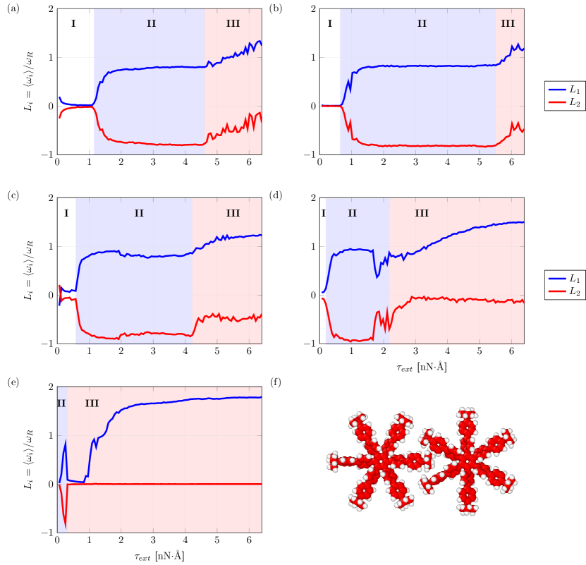
For this optimal separation nm, we have then added additional gears to the train to see over how many gears rotational transmission is still feasible. In Fig. 9 we show the locking coefficients for HB-BPB gears.
First of all, we see that adding gears leads to a reduction in the values of the locking coefficients within the driving phase. If the locking coefficients decrease, this suggests additional energy dissipation during the rotational process. In fact, with increasing number of gears, a more detailed analysis of the MD simulations showed that collective rotations gradually become a set of internal torsional motions propagating among gears. In Fig. 9 (b), we can see that we have regions I, II, and III. Therefore, collective rotations for three gears are possible. On the other hand, in region III, we found that the locking coefficients satisfy . This means that one overdrives the first gear but the second and third gears are still interlocked and can sometimes still follow the first gear. For four gears (see Fig. 9 (c)), collective rotations happen as well but in region III the locking coefficients satisfy , meaning that the first gear is overdriven, but only the second gear can sometimes follow and the others stay still. For five gears (in Fig. 9 (d)), region II completely vanishes, so that collective rotations are fully blocked. In region III, we have a similar situation as in the four gears case: , so that the first gear rotates very fast and only the second gear can follow at some point. Note also that in region I, we found very small nonzero values for all locking coefficients: . This is related to the fact that internal torsional motions are propagating from the first gear to the remaining gears, but the whole process is very slow and gets stuck eventually. Hence, the average angular velocity for all gears is nonzero but very small.
These results suggest that transmission of rotational motion may work up to gears, but one needs to further investigate this issue by including e.g. a substrate and analyzing which dissipation channels become efficient in this case. The problem can be, however, very difficult since not only phononic dissipation is expected to occur, but also electronic friction, requiring a quantum mechanical treatment.
4 Conclusions and Outlook
In conclusion, we have shown how atomistic classical Molecular Dynamics simulations can contribute to shed light on different issues related to the dynamics of nanoscale gears. In the first part of this Chapter we demonstrated that the regime of viscous dissipation can emerge out of van-der-Waals interactions between gears and substrates. The fitted exponential decay of the angular velocity allowed, additionally, to obtain an estimate of the typical relaxation time scales associated with the process. Moreover, by changing the substrates and the gear sizes, we found out that the relaxation time monotonically decreases with decreasing gear size for amorphous SiO2, but it is weakly dependent on size for crystalline SiO2 and nearly size-independent for graphene, a result which correlates well with the differences in the degree of atomic-scale corrugation of these three substrates. We also identified the energy transfer between gear and substrate as the main energy dissipation channel involving the excitation of surface vibrational modes.
In the second part of the Chapter, we investigated a heterogeneous pair of gears, consisting of a solid-state graphene nanodisk whose edge was regularly functionalized with chemical groups acting as atomic scale teeth. The latter were able to efficiently mediate the transfer of angular momentum to a single molecule gear upon the application of an external torque. Similar to previous studies on molecule gear trainsLin2019a we could identify underdriving, driving and overdriving phases as a function of the applied torque. Moreover, we estimated the contribution of phononic and electronic energy dissipation channels leading eventually to a damping of the rotational motion of the master (graphene nanodisk). Our results support the use of superconducting surfaces in order to suppress electronic friction contributionsWeiHyo2019 . We also showed that the locking coefficient is a reasonable descriptor not only to classify the different driving regimes but also to help in the selection of appropriate molecule gear candidates.
In relation to frictional effects, future research lines will need to address in more detail rotational energy dissipation at the single molecule gear level, which will involve dealing not only with excited vibrational modes on the substrate, but also (for metallic substrates) with electronic dissipation channels. This will require the use of more advanced first-principle methodologies or reactive force-fields (like ReaxFF)Chenoweth2008 (if MD simulations are the goal). From the more phenomenological perspective, it would be interesting to develop effective models to describe rotational damping along lines similar to the formulation of the Caldeira-Leggett and Rubin modelsWeiss2012 , which are based in tracing out bath degrees of freedom and its inclusion in effective memory kernels, leading to a very rich physics.
One important point not covered in this short review and, in general, not well-understood is the mechanism for triggering the rotation of molecule gears. While the ”mechanics” of pushing a molecule gear with an STM tip may be understood with the help of ab initio approaches and MD simulations, the excitation of a collective rotation via voltage pulses is considerably less clearLin2019 ; PES . For instance, what breaks the rotational symmetry? Which molecular orbitals are involved? How the inelastic electronic excitation can be ”converted” into the excitation of a collective coordinate leading to a concerted motion (rotation) of the molecular frame? The theoretical description of these effects may require the use of quantum master equation approaches or mixed quantum-classical methodologies.
Acknowledgements.
We would like to thank C. Joachim, J. Heinze, A. Mendez, A. Raptakis, T. Kühne, D. Bodesheim, S. Kampmann, R. Biele, D. Ryndyk, A. Dianat, and F. Moresco for very useful discussions and suggestions. This work has been supported by the International Max Planck Research School (IMPRS) for “Many-Particle Systems in Structured Environments” and also by the European Union Horizon 2020 FET Open project ”Mechanics with Molecules” (MEMO, grant nr. 766864).References
- (1) Y. Ju Yun, C. Seong Ah, S. Kim, W. Soo Yun, B. Chon Park, D. Han Ha, Nanotechnology 18(50), 505304 (2007). DOI 10.1088/0957-4484/18/50/505304
- (2) J. Yang, J. Deng, C. Troadec, T. Ondarçuhu, C. Joachim, Nanotechnology 25(46), 465305 (2014). DOI 10.1088/0957-4484/25/46/465305
- (3) D. Mailly, G. Faini, in Build. Probing Small Mech. (Springer, Cham, 2020), chap. 4, pp. 41–63. URL http://link.springer.com/10.1007/978-3-030-56777-4{\_}4
- (4) C. Joachim (ed.), Building and Probing Small for Mechanics. Advances in Atom and Single Molecule Machines (Springer International Publishing, Cham, 2020). DOI 10.1007/978-3-030-56777-4
- (5) Y. Gisbert, S. Abid, G. Bertrand, N. Saffon-Merceron, C. Kammerer, G. Rapenne, Chem. Commun. 55(97), 14689 (2019). DOI 10.1039/C9CC08384G
- (6) R.K. Soong, Science (80-. ). 290(5496), 1555 (2000). DOI 10.1126/science.290.5496.1555
- (7) J. Deng, C. Troadec, F. Ample, C. Joachim, Nanotechnology 22(27), 275307 (2011). DOI 10.1088/0957-4484/22/27/275307
- (8) H.H. Lin, J. Heinze, A. Croy, R. Gutierrez, G. Cuniberti, in Build. Probing Small Mech. (Springer Nature Switzerland AG, 2020), chap. 11, pp. 165–180. DOI 10.1007/978-3-030-56777-4–“˙˝11. URL http://arxiv.org/abs/2004.09857http://link.springer.com/10.1007/978-3-030-56777-4{\_}11
- (9) H.H. Lin, A. Croy, R. Gutierrez, C. Joachim, G. Cuniberti, Phys. Rev. Applied 13, 034024 (2020). DOI 10.1103/PhysRevApplied.13.034024
- (10) R. Zhao, Y.L. Zhao, F. Qi, K.E. Hermann, R.Q. Zhang, M.A. Van Hove, ACS Nano 12(3), 3020 (2018). DOI 10.1021/acsnano.8b00784
- (11) L. Chen, F. Qi, K. Jitapunkul, Y. Zhao, R. Zhang, M.A. Van Hove, J. Phys. Chem. A 122(38), 7614 (2018). DOI 10.1021/acs.jpca.8b04368
- (12) R. Zhao, F. Qi, Y.L. Zhao, K.E. Hermann, R.Q. Zhang, M.A. Van Hove, J. Phys. Chem. Lett. 9(10), 2611 (2018). DOI 10.1021/acs.jpclett.8b00676
- (13) H.H. Lin, J. Heinze, A. Croy, R. Gutiérrez, G. Cuniberti. Effect of lubricants on the rotational transmission between solid-state gears (2021)
- (14) S.B. Ahmed, N. Ullah, Y. Zhao, R. Zhang, M.A. Van Hove, The Journal of Physical Chemistry C 125(32), 17612 (2021). DOI 10.1021/acs.jpcc.1c04239
- (15) J. Echeverria, S. Monturet, C. Joachim, Nanoscale 6(5), 2793 (2014). DOI 10.1039/c3nr05814j
- (16) H.H. Lin, A. Croy, R. Gutierrez, C. Joachim, G. Cuniberti, J. Phys. Commun. 3(2), 025011 (2019). DOI 10.1088/2399-6528/ab0731
- (17) A. Vanossi, N. Manini, M. Urbakh, S. Zapperi, E. Tosatti, Rev. Mod. Phys. 85(2), 529 (2013). DOI 10.1103/RevModPhys.85.529
- (18) E. Gnecco, E. Mayer, Fundamentals of Friction and Wear. NanoScience and Technology (Springer Berlin Heidelberg, Berlin, Heidelberg, 2007). DOI 10.1007/978-3-540-36807-6
- (19) B. Perssson, E. Tosatti, Physics of Sliding Friction, vol. 311 (Springer Netherlands, Dordrecht, 1996). DOI 10.1007/978-94-015-8705-1
- (20) S. Wen, P. Huang, Principles of Tribology (John Wiley & Sons Singapore Pte. Ltd., Singapore, 2017). DOI 10.1002/9781119214908
- (21) N. Manini, O.M. Braun, E. Tosatti, R. Guerra, A. Vanossi, J. Phys. Condens. Matter 28(29), 293001 (2016). DOI 10.1088/0953-8984/28/29/293001
- (22) K.M. Sankar, D. Kakkar, S. Dubey, S.V. Garimella, M. Goyat, S. Joshi, J.K. Pandey, Proc. Inst. Mech. Eng. Part J J. Eng. Tribol. 234(3), 448 (2020). DOI 10.1177/1350650119863993
- (23) M.S. Lodge, C. Tang, B.T. Blue, W.A. Hubbard, A. Martini, B.D. Dawson, M. Ishigami, Sci. Rep. 6(1), 31837 (2016). DOI 10.1038/srep31837
- (24) E.D. Smith, M.O. Robbins, M. Cieplak, Phys. Rev. B 54(11), 8252 (1996). DOI 10.1103/PhysRevB.54.8252
- (25) M. Walker, C. Jaye, J. Krim, M.W. Cole, J. Phys. Condens. Matter 24(42), 424201 (2012). DOI 10.1088/0953-8984/24/42/424201
- (26) G. Binnig, H. Rohrer, Rev. Mod. Phys. 59(3), 615 (1987). DOI 10.1103/RevModPhys.59.615
- (27) S.G. Balakrishna, A.S. de Wijn, R. Bennewitz, Phys. Rev. B 89(24), 245440 (2014). DOI 10.1103/PhysRevB.89.245440
- (28) G. Tomlinson, London, Edinburgh, Dublin Philos. Mag. J. Sci. 7(46), 905 (1929). DOI 10.1080/14786440608564819
- (29) O.M. Braun, Y.S. Kivshar, The Frenkel-Kontorova Model (Springer Berlin Heidelberg, Berlin, Heidelberg, 2004). DOI 10.1007/978-3-662-10331-9
- (30) E. Panizon, G.E. Santoro, E. Tosatti, G. Riva, N. Manini, Phys. Rev. B 97(10), 104104 (2018). DOI 10.1103/PhysRevB.97.104104
- (31) R. Guerra, U. Tartaglino, A. Vanossi, E. Tosatti, Nat. Mater. 9(8), 634 (2010). DOI 10.1038/nmat2798
- (32) M.S. Tomassone, J.B. Sokoloff, A. Widom, J. Krim, Phys. Rev. Lett. 79(24), 4798 (1997). DOI 10.1103/PhysRevLett.79.4798
- (33) C. Manzano, W.H. Soe, H.S. Wong, F. Ample, A. Gourdon, N. Chandrasekhar, C. Joachim, Nat. Mater. 8(7), 576 (2009). DOI 10.1038/nmat2467
- (34) F. Chiaravalloti, L. Gross, K.H. Rieder, S.M. Stojkovic, A. Gourdon, C. Joachim, F. Moresco, Nat. Mater. 6(1), 30 (2007). DOI 10.1038/nmat1802
- (35) F. Moresco, in Single Mol. Mach. Mot. Adv. Atom Single Mol. Mach. Springer, Cham (2015), pp. 165–186. DOI 10.1007/978-3-319-13872-5–“˙˝10. URL http://link.springer.com/10.1007/978-3-319-13872-5{\_}10
- (36) P. Mishra, J.P. Hill, S. Vijayaraghavan, W.V. Rossom, S. Yoshizawa, M. Grisolia, J. Echeverria, T. Ono, K. Ariga, T. Nakayama, C. Joachim, T. Uchihashi, Nano Lett. 15(7), 4793 (2015). DOI 10.1021/acs.nanolett.5b01908
- (37) U.G.E. Perera, F. Ample, H. Kersell, Y. Zhang, G. Vives, J. Echeverria, M. Grisolia, G. Rapenne, C. Joachim, S.W. Hla, Nat. Nanotechnol. 8(1), 46 (2013). DOI 10.1038/nnano.2012.218
- (38) K.H. Au Yeung, T. Kühne, F. Eisenhut, M. Kleinwächter, Y. Gisbert, R. Robles, N. Lorente, G. Cuniberti, C. Joachim, G. Rapenne, C. Kammerer, F. Moresco, J. Phys. Chem. Lett. (111), 6892 (2020). DOI 10.1021/acs.jpclett.0c01747
- (39) W.H. Soe, S. Srivastava, C. Joachim, J. Phys. Chem. Lett. 10(21), 6462 (2019). DOI 10.1021/acs.jpclett.9b02259
- (40) Y. Zhang, H. Kersell, R. Stefak, J. Echeverria, V. Iancu, U.G.E. Perera, Y. Li, A. Deshpande, K.F. Braun, C. Joachim, G. Rapenne, S.W. Hla, Nat. Nanotechnol. 11(8), 706 (2016). DOI 10.1038/nnano.2016.69
- (41) S. Plimpton, J. Comput. Phys. 117(1), 1 (1995). DOI 10.1006/jcph.1995.1039
- (42) J. Tersoff, Phys. Rev. B 37(12), 6991 (1988). DOI 10.1103/PhysRevB.37.6991
- (43) S.J. Stuart, A.B. Tutein, J.A. Harrison, J. Chem. Phys. 112(14), 6472 (2000). DOI 10.1063/1.481208
- (44) H.H. Lin, A. Croy, R. Gutierrez, G. Cuniberti, Phys. Rev. Appl. 15(2), 024053 (2021). DOI 10.1103/PhysRevApplied.15.024053
- (45) S. Nosé, J. Chem. Phys. 81(1), 511 (1984). DOI 10.1063/1.447334
- (46) W.G. Hoover, Phys. Rev. A 31(3), 1695 (1985). DOI 10.1103/PhysRevA.31.1695
- (47) H.H. Lin, A. Croy, R. Gutierrez, C. Joachim, G. Cuniberti, Phys. Rev. Appl. 13(3), 034024 (2020). DOI 10.1103/PhysRevApplied.13.034024
- (48) B. Persson, A. Nitzan, Surf. Sci. 367(3), 261 (1996). DOI 10.1016/S0039-6028(96)00814-X
- (49) R.L. Norton, Machine Design: An Integrated Approach, 4th Edition (Prentice Hall, 2010)
- (50) S.V. Meshkov, Phys. Rev. B 55(18), 12113 (1997). DOI 10.1103/PhysRevB.55.12113
- (51) C. Lee, D. Vanderbilt, K. Laasonen, R. Car, M. Parrinello, Phys. Rev. B 47(9), 4863 (1993). DOI 10.1103/PhysRevB.47.4863
- (52) B. Wehinger, A. Bosak, K. Refson, A. Mirone, A. Chumakov, M. Krisch, J. Phys. Condens. Matter 27(30), 305401 (2015). DOI 10.1088/0953-8984/27/30/305401
- (53) H.H. Lin, A. Croy, R. Gutierrez, C. Joachim, G. Cuniberti, Nanotechnology 33(17), 175701 (2022). DOI 10.1088/1361-6528/ac4b4b
- (54) A. MacKinnon, Nanotechnology 13(5), 678 (2002). DOI 10.1088/0957-4484/13/5/328
- (55) B.N.J. Persson, J. Chem. Phys. 113(13), 5477 (2000). DOI 10.1063/1.1290025
- (56) B.N.J. Persson, A.I. Volokitin, J. Chem. Phys. 103(19), 8679 (1995). DOI 10.1063/1.470125
- (57) M.A. Ordal, R.J. Bell, R.W. Alexander, L.L. Long, M.R. Querry, Appl. Opt. 24(24), 4493 (1985). DOI 10.1364/AO.24.004493
- (58) N.W. Ashcroft, N.D. Mermin, Solid State Physics (Holt, Rinehart and Winston, 1976)
- (59) P. Kumar, Y.S. Chauhan, A. Agarwal, S. Bhowmick, J. Phys. Chem. C 120(31), 17620 (2016). DOI 10.1021/acs.jpcc.6b05805
- (60) K. Chenoweth, A.C.T. van Duin, W.A. Goddard, J. Phys. Chem. A 112(5), 1040 (2008). DOI 10.1021/jp709896w
- (61) U. Weiss, Quantum Dissipative Systems (WORLD SCIENTIFIC, 2012). DOI 10.1142/8334