Cyclotron Beam Extraction by Acceleration
Abstract
One of the decisive issues in the design and operation of cyclotrons is the choice of the beam extraction method. Typical methods are extraction by electrostatic extractors and by stripping. The former method requires DC high voltage electrodes which are notorious for high-voltage breakdowns. The latter method requires beams of atomic or molecular ions which are notorious for rest gas and Lorentz stripping. Here we discuss the conditions to be met such that a beam will leave the magnetic field of an isochronous cyclotron purely by fast acceleration.
I Introduction
The extraction method is a decisive choice for the design of isochronous cyclotrons Richardson ; Craddock ; Stammbach1992 ; Onishchenko2008 ; Calabretta2016 ; Seidel2021 ; Seidel2018 ; Kleeven2006 . Specifically in case of high intensity beams, extraction losses have to be minimized in order to avoid activation of the machine components Blaser1963 . The extraction methods used most frequently are stripping extraction RICKEY1962 ; SCHWABE1996 ; Djurovic2001 ; Mackenzie1984 ; MEC and extraction by electrostatic deflectors Martin1963 ; Gunder1963 . Both methods have their advantages and issues.
Stripping extraction, i.e. the removal of electrons by the passage of an ion beam through thin stripper foils, requires the acceleration of ions that are not fully stripped yet, for instance of -ions or -molecules. But since not fully ionized atoms (or molecules) have a considerably larger scattering cross-section with the rest gas molecules, some losses in the course of acceleration are unavoidable. Besides rest gas stripping also Lorentz stripping may result in losses Hiskes1961 ; Stinson1969 ; Keating1995 ; LStrip ; Calvo2021 . Therefore stripping extraction requires an excellent vacuum and the Lorentz stripping effect limits both, the maximal beam energy and the maximal magnetic field. Low-loss extraction by electrostatic deflectors, on the other hand, is notorious for beam interruptions by high voltage breakdowns and requires well-separated turns in order to place the extraction septum between turns.
Despite these issues, isochronous cyclotrons are attractive for the production of high intensity CW beams, due to their superior energy efficiency Grillb2017 , their small footprint, and their relatively low cost. Therefore the use of cylotrons for the production of high intensity beams has been suggested in various projects, typically aiming for several of beam current at energies between and , for instance for ADS systems, neutron production and also neutrino physics STAMMBACH1996 ; Alenitsky2011 ; WINKLEHNER2018 ; Yang2016 . A cyclotron facility that often serves as a proof-of-principle-machine for these objectives is the high intensity proton accelerator (HIPA) facility of the Paul Scherrer Institute (PSI) in Switzerland, which provides up to of protons at hipa_acc .
In 1981 Werner Joho formulated “Joho’s law”, which states that the possible beam intensity, for the same losses, increases with the inverse of the third power of the number of turns Joho1981 . This law has been verified with astonishing accuracy at the PSI Ring cyclotron hipa_acc . Hence we can reasonably assume that any high intensity proton machine will aim for the lowest possible number of turns, that is, for the highest possible acceleration voltage, mostly in order to provide the highest possible turn separation at extraction. The incredible increase of beam current from the PSI Ring machine has been achieved by the insertion of a flat-topping cavity and by the reduction of the number of turns, from originally more than to now hipa_acc with an upgrade of the rf cavities and amplifier chains. However, the reduction of the turn number has a side effect which has not received much attention, namely that the total phase shift of the beam by the fringe field near the outer radius is significantly reduced.
In 1995, Yves Jongen proposed the so-called “self-extraction”, a method to design cyclotrons such that the beam would leave the field without stripper or electrostatic extractor Jongen1995 . A cyclotron build by IBA provided the proof-of-principle Kleeven2001 for this extraction method. However, a theoretical account of the conditions that have to be met to allow for beam escape has, to the knowledge of the author, not been provided so far.
Here we report about the fact that the design of high energy high intensity separate sector cyclotrons of the PSI type meets the main requirements for auto-escape of the beam without electrostatic deflectors.
II The Cyclotron Bending Limit
The main aim of the reduction of the turn number in the Ring cyclotron is the increase of the turn separation so that the septum of the electrostatic extractor can be placed between cleanly separated turns. This is required not only in order to avoid an overheating of the septum, but also to minimize beam loss and activation of the septum and subsequent beamline elements. Isochronous cyclotrons are efficient because they operate at constant magnetic field and constant rf-frequency. This allows for narrow-band rf structures with high Q-factors. Furthermore the beam passes the same rf-structure multiple times which also increases the efficiency of the acceleration. However, this method requires that the circulation frequency of the beam stays in sync with the frequency of the rf system. The average magnetic field must then increase radially with the relativistic -factor and since the velocity is approximately given by , the (average) field must approximately follow
| (1) |
Therefore the isochronism of a cyclotron can not be sustained in the fringe field due to the radial decrease of the magnetic field. Hence the phase between beam and accelerating rf will shift in the course of extraction and the bunches will get more and more out of sync with the accelerating rf.
Let the energy gain per turn be given by
| (2) |
where is the phase of the beam (relative to the rf-phase) and is the maximum accelerating voltage per turn. If the beam is not extracted fast enough, the phase will be shifted beyond and the beam will loose instead of gain energy when passing the next rf cavity.
Hence there is another important consequence of the reduction of turn number in isochronous cyclotrons: The maximum energy that the beam is able to reach depends crucially of the phase shift in the fringe field. On the other hand, it is evident that any finite field can only hold a circulating beam up to a finite momentum.
The relation between momentum , radius and magnetic field is given by
| (3) |
so that
| (4) |
The factor is the field index111 The usual convention is , but the cyclotron literature mostly uses the positive sign convention. The maximum momentum is given by which corresponds to a field index of . Beyond the point, where the radial field gradient in the fringe field region is steeper than , the beam can not stay within the machine. Hence there is a maximum radius
| (5) |
which corresponds to the maximum momentum
| (6) |
Let us call this momentum and the corresponding energy the escape momentum and escape energy.
Hence there are two maximum values for the radius, firstly the radius where the phase shift reaches and secondly the radius of the maximum momentum. The decisive question is therefore, which of these radii is larger. This depends on two factors, firstly the exact shape of the fringe field and secondly, the accelerating voltage . The latter is in the general case a function of radius as well, but since this dependency is usually small (over the region of interest, i.e. the extraction), we shall neglect it in the following.
The reduction of the turn number has, as mentioned before, the main purpose to increase the turn separation. Since energy, radius and momentum have mutual bijective relationships, the radius gain per turn in a cyclotron is, in sectorless approximation, given by
| (7) |
From Hamilton’s equation of motion it is known that , so that one obtains with Eq. 2 and Eq. 4:
| (8) |
which can be reformulated as
| (9) |
Both, energy and radius vary only a little over the region of interest. The dominating factors are therefore and . The question is then, whether the radius for or the radius for is smaller. When the phase approaches before approches , then the turn separation will typically decrease to zero and then become negative, so that the -loop closes. However, if the phase stays well below when approches , then the beam will escape the field simply because the momentum exceeds the bending limit.
III Estimation of the Acc. Voltage Required to Reach the Escape Energy
If is the azimuthal angle and the phase of the rf, then the phase shift per time in an isochronous cyclotron can be written as
| (10) |
where is the actual revolution frequency of the bunch and is the so-called harmonic number, that is the number of rf-cycles per revolution of the bunch. The number of revolutions per time is
| (11) |
so that
| (12) |
where is the time required per revolution. The relation between the revolution frequency of a particle with charge and mass in the magnetic field can be written as
| (13) |
In perfectly isochronous machines the field is given by
| (14) |
where is the “nominal” revolution frequency. Often the cyclotron radius is used to write this as
| (15) |
where is understood purely as a function of the radius.
Let us assume that the the fringe field can be approximated by an Enge type function Enge1964 ; Enge1967 of the simplest form so that the real (azimuthally averaged) magnetic field is given by
| (16) |
with
| (17) |
where is approximately half of the pole air gap 222 The exact value depends on the details of the iron geometry. and is the radius for which the field is half of the isochronous field, i.e. . The radial derivative of is then
| (18) |
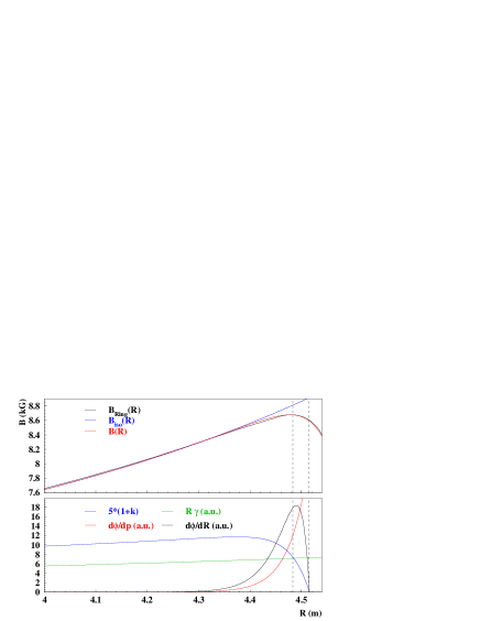
Fig. 1 shows how this approximation compares to the (azimuthal) average field of the PSI Ring cyclotron. For our purposes the agreement is – within the region of interest – reasonable, even though the parameters obtained from this “fit” do not agree very well with the real Ring cyclotron.
The field index is then given by
| (19) |
The revolution frequency can then be expressed by
| (20) |
where is the usual relativistic factor, that is, a function of velocity:
| (21) |
In the sectorless approximation the velocity is given by
| (22) |
so that is given by
| (23) |
This can be used to find the radial dependency of :
| (24) |
If the cyclotron is isochronous up to the fringe region, then and therefore Eq. LABEL:eq_phaseshift0 yields
| (25) |
The phase shift per energy gain can be expressed, using Eq. 2, by
| (26) |
and per momentum gain by
| (27) |
The velocity can be replaced by the use of Eq. 22 so that:
| (28) |
In order to obtain the phase shift as a function of radius, one may use Eq. 4 to obtain
| (29) |
Introducing the abbreviation
| (30) |
together with Eq. LABEL:eq_k and Eq. 24 one obtains:
| (31) |
and hence
| (32) |
As shown in Fig. 1, the phase and the term vary fast over the fringe field region, while the relative change of and are small. Hence it is a reasonable approximation to keep the latter constant in the integration. This means that we fix and , where the subscript “x” indicates that these are the values at extraction.
From Eq. 18 one obtains
| (33) |
One may express the phase factor by its Taylor series (using as variable, located at ):
| (34) |
and since is small, one may use the first term only. Then the integrand simplifies to:
| (35) |
The integration over the fringe field region starts with and ends where , which corresponds (see Eq. LABEL:eq_k) to , so that the leading term after integration is:
| (36) |
where is the initial phase (prior to extraction) and is the final phase. If the initial phase is zero (), the condition yields , then the accelerating voltage which suffices to reach the escape energy, is finally (skipping the subscript ):
| (37) |
With and this can also be written as
| (38) |
where and are the (kinetic) extraction energy and radius. Since the number of turns is approximately , one finds
| (39) |
Hence it is mostly the squared ratio of extraction radius and pole gap at extraction which determines the maximal number of turns or the minimal energy gain, respectively. The compact superconducting cyclotron COMET Schillo ; Geisler2007 , which provides the proton beam for the proton therapy facility Proscan at PSI, has a half-gap of , an extraction radius of and a harmonic number of . According to Eq. 39, escape extraction is then possible for a maximum turn number of about . This compares to an actual turn number of about , i.e. eight times as much. Hence the beam would be able to escape without extractor under these conditions, if the half-gap would be (reduced to) less than .
However, for the PSI Ring cyclotron, Eq. 37 results, using the parameters obtained from the azimuthal average field (i.e. ), in a minimal voltage of
| (40) |
The numerical integration of Eq. LABEL:eq_dphdR for the same parameters yields a voltage of as required to reach the escape energy, which is in reasonable agreement with our approximation. This voltage is close to the average voltage actually used today in the PSI Ring cyclotron, which is about .
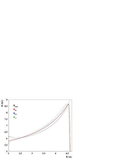
But the azimuthal average of the field is not a good approximation for separate sector cyclotrons. A realistic value of the half-gap at extraction is about . As shown in Fig. 3, the fall-off of the maximal field values is much steeper than that of the azimuthal average. Specifically the parameter is less than half of the value obtained from the azimuthal average (and closer to the real half-gap)444The most accurate determination of the field shape as “seen by the beam” would derive from the average field along the scalloping closed orbits. But stable closed orbits do not exist beyond . . Hence the required voltage might well be a factor of smaller, i.e. as low as or even less.
Fig. 3 shows results of direct orbit tracking555 We use CYBORC (“Cyclotron Beam Orbit Calculator”) for the tracking, a “C”-implementation of a 4th-order Runge-Kutta solver for the equations of motion on a polar grid Gordon84 . The field map of the PSI Ring Seidel2021 that we used for the tracking is based on measured data Willax1969 ; Willax72 ; Adam1975 and has been used in several other recent publications, for instance Refs. Yang2010 ; Bi2011 ; Frey2019 . , starting at and zero phase, which show that beam escape is possible for less than about turns, i.e. for an energy gain per turn of more than . This is indeed by a factor of about below the currently used acceleration voltage.
Therefore the acceleration of the beam in the PSI Ring machine is so fast that the beam approaches the bending limit before the beam phase is shifted to . The beam would escape the magnetic field without any extraction device.
Hence the acceleration of the beam in the PSI Ring machine is so fast that it would reach the bending limit before the phase is shifted to . The beam would escape the magnetic field without any extraction device.
Nonetheless the beam has to pass the fringe field region, where the negative -values lead to a strong radial defocusing and vertical focusing. Both effects have to be compensated if one aims to make practical use of escape extraction. Furthermore, since the beam has to pass the -resonance, it is required to precisely control the first harmonic content of the field prior to extraction.
IV Extraction by Acceleration from the PSI Ring cyclotron
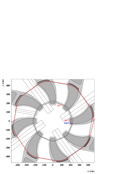
Fig. 4 shows the iron shape of the PSI Ring cyclotron, some accelerated orbits and the last orbit which escapes the field without electrostatic extractor. The positions of the four accelerating cavities (plus one flat-topping cavity) are indicated by the five rectangular boxes. The cavities provide enough energy gain per turn to extract the beam after about turns hipa_acc . Currently the Ring cyclotron uses an electrostatic extractor to extract the beam at , i.e. before the maximum field is reached.
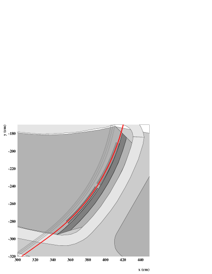
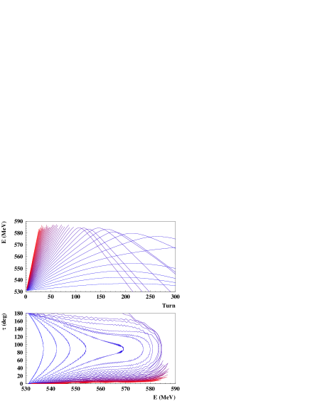
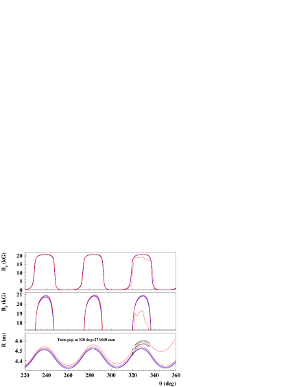
Figs. 4 and 5 show the escape extraction of nine orbits. Besides a central (“reference”) orbit, we tracked orbits with a different starting radius (), orbits with different initial energy (), initial radial momentum () 666To obtain the momentum in SI units, one has to multiply by . and rf phase (). It is not only that the orbit escapes the field, as shown in Fig. 6, but furthermore the field gradient is positive or zero up to the last sector before escape. Hence the orbit “sees” a substantial negative field gradient only for a short time. Hence a single gradient corrector might be sufficient to keep the beam radially compact. The magnetic field gradient is of the order of , i.e. a value for which a compensation might be possible, at least in principle.
However, the upper and lower half-poles of the PSI Ring cyclotron are connected by a non-magnetic support at the (inner and) outer pole radius. The orbit of the extracted beam would come close to the support structure, which is welded to the poles as a part of the vacuum chamber (shown in dark gray in Fig. 5). This leaves few space for the installation of corrector magnets. A modification of the support structure would imply severe practical difficulties and a long interruption of user data taking. However in case of new cyclotron projects, the sketched extraction method seems to be a promising possibility.
V Discussion and Outlook
In new high intensity cyclotron project the design and shape of the magnetic fringe field and of mechanical components around it could be optimized for escape extraction. Since electrostatic extractors are notorious for high voltage breakdowns, this option might specifically be interesting in cases where the number of acceptable beam interruptions is rigorously limited (as for instance in case of ADS). The negative field gradient in the fringe field requires the use of magnetic gradient correctors Kleeven2001 . As shown in Fig. 6, the field of the last turn is larger than that of the previous turn up to the last two sectors and is significantly lower only in the last sector. The extraction is therefore reasonably fast. A gradient corrector magnet, no matter if active or passive, will almost certainly lead to a lower number of beam interruptions than electrostatic extractors. Due to Joho’s “ law” one can reasonably assume that any high-intensity and low-loss proton machine aiming for beam power in the multi-MW-range will require a high energy gain per turn. The possibility of escape extraction might, under these conditions, be regarded as a side-effect of high intensity operation.
The voltage and power that can be provided by a single cavity has practical limitations. The PSI main cavities, for instance, are specified for power losses of Fitze . Hence the four main cavities of the PSI Ring cyclotron restrict the maximum power loss to . If one takes this as the state-of-the-art, then a multi-MW-cyclotron would require substantially more cavities than the PSI Ring cyclotron. Furthermore the power loss in rf cavities is proportional to the square of the cavity voltage Grilli2016 ; hipa_acc . Therefore the cavity wall losses increase by a factor of four when the voltage is doubled, but only by a factor of two when the number of cavities is doubled. Hence the use of a higher number of cavities is beneficial for the energy efficiency as well. A high number of cavities naturally suggests a high number of sectors for high power proton cyclotrons. This requires space and hence an increase in radius. Though size seems to be an important criterion, the size of a high intensity cyclotrons is negligible when compared to the size of linacs for similar energies. The MYRRHA linac, designed to provide at , for instance, has a length of DEBRUYN2015 .
In the PSI machine, the effective turn separation between the last two turns is, for a centered beam, , which can be enhanced up to by betatron oscillations hipa_acc . This is still substantially smaller than the pole gap. Therefore the radial turn separation is as yet the bottleneck for high intensity operation. Hence new high power cyclotrons aiming for power levels in the MW-regime, will likely be designed with a considerably larger extraction radius than the PSI Ring cyclotron, but not necessarily with a much larger pole gap. Then the ratio of pole gap to extraction radius (and hence the required voltage for escape extraction) will naturally be lower than (or equal to) the ratio of the PSI Ring cyclotron and this will facilitate escape extraction even further. Due to these arguments we believe that it is worthwhile to further investigate the feasibility of extraction purely by acceleration – specifically in high power cyclotrons.
VI Acknowledgements
The figures have been generated with the CERNLIB (PAW) and XFig.
References
- (1) J. Reginald Richardson. Sector focusing cyclotrons. Progress in Nuclear Techniques and Instrumentation, 1:3–99, 1965.
- (2) M. K. Craddock and K. R. Symon. Cyclotrons and fixed-field alternating-gradient accelerators. Reviews of Accelerator Science and Technology, 1(1):65–97, 2008.
- (3) Th. Stammbach. Introduction to cyclotrons. In Stuart Turner, editor, Proceedings of the 1992 CERN Accelerator School: Cyclotrons, Linacs and Their Applications, pages 113–133. CERN, 1992.
- (4) L. M. Onishchenko. Cyclotrons: A survey. Physics of Particles and Nuclei, 39(6):950, Nov 2008.
- (5) L. Calabretta and M. Seidel. 50 years of cyclotron development. IEEE Transactions on Nuclear Science, 63(2):965–991, 2016.
- (6) Mike Seidel. Cyclotrons and Fixed Field Alternating Gradient Accelerators. arXiv:2105.04477, 2021.
- (7) Mike Seidel. Injection and Extraction in Cyclotrons. Proceedings of the CAS-CERN Accelerator School on Beam Injection, Extraction and Transfer, 5, 2018.
- (8) W. Kleeven. Injection and extraction for cyclotrons. Proceedings of the CERN Accelerator School (CAS), 2006.
- (9) J.P. Blaser, Ch. Perret, M. Barbier, and J. Dutrannois. Shielding and Activation of High-Intensity Cylotrons. In Howard and Vogt-Nilsen cyc:1963 , pages 157–164.
- (10) M.E. Rickey and Rodman Smythe. The acceleration and extraction of negative hydrogen ions in the c.u. cyclotron. Nuclear Instruments and Methods, 18-19:66–69, 1962.
- (11) J. Schwabe. Magnetic dissociation conditions of acceleration of , beams on the AIC-144 S cyclotron. Nuclear Instruments and Methods in Physics Research Section A: Accelerators, Spectrometers, Detectors and Associated Equipment, 373(1):1–9, 1996.
- (12) Jasna L. Ristic-Djurovic. Stripping extraction of positive ions from a cyclotron. Phys. Rev. ST Accel. Beams, 4:123501, Dec 2001.
- (13) G.H. Mackenzie, M. Zach, R.E. Laxdal, J.R. Richardson, M.K. Craddock, and G. Dutto. Plans for the Extraction of Intense Beams of Ions from the TRIUMF Cyclotron. In F. Marti, editor, Proceedings of the 10th International Conference on Cyclotrons and their Applications, pages 233–236, Piscataway, USA, Sep 1984. IEEE.
- (14) C. Baumgarten. Cyclotrons with fast variable and/or multiple energy extraction. Phys. Rev. ST Accel. Beams, 16:100101, Oct 2013.
- (15) J. A. Martin. Beam Extraction from Sector-Focused Cyclotrons. In Howard and Vogt-Nilsen cyc:1963 , pages 48–51.
- (16) H. A. Grunder, F. B. Selph, and H. Atterling. Operating Experience with the Berkeley 88 - Inch Electrostatic Deflector. In Howard and Vogt-Nilsen cyc:1963 , pages 59–71.
- (17) John R. Hiskes. Dissociation of molecular ions by electric and magnetic fields. Phys. Rev., 122:1207–1217, May 1961.
- (18) G. M. Stinson, William Charles Olsen, W. J. McDonald, David Arnold Axen, and Ewart William Blackmore. Electric dissociation of ions by magnetic fields. Technical Report TRI-69-1, TRIUMF, Vancouver, BC, Canada, 1969.
- (19) P. B. Keating, M. S. Gulley, H. C. Bryant, E. P. MacKerrow, W. A. Miller, D. C. Rislove, Stanley Cohen, J. B. Donahue, D. H. Fitzgerald, David J. Funk, S. C. Frankle, R. L. Hutson, R. J. Macek, M. A. Plum, N. G. Stanciu, O. B. van Dyck, and C. A. Wilkinson. Electric-field-induced electron detachment of 800-mev ions. Phys. Rev. A, 52:4547–4555, Dec 1995.
- (20) T.J. Zhang, J.Q. Zhong, J.Z. Wang, G. Dutto, G.H. Mackenzie, L.W. Root, X.L. Jia, Y.J. Bi, F.P. Guan, and S.M. Wei. Beam loss by lorentz stripping and vacuum dissociation in a 100 mev compact cyclotron. In Martin Comyn, Shane Koscielniak, Volker R. W. Schaa, and Paul W. Schmor, editors, Proceedings of the 23rd Particle accelerators Conference (PAC’09), pages 5035–5037, Geneva, Switzerland, 2009. JACoW.
- (21) P. Calvo, I. Podadera, D. Gavela, C. Oliver, A. Adelmann, J. Snuverink, and A. Gsell. Beam stripping interactions in compact cyclotrons. Phys. Rev. Accel. Beams, 24:090101, Sep 2021.
- (22) J. Grillenberger, S-H. Kim, M. Yoshii, M. Seidel, and V.P. Yakovlev. The Energy Efficiency of High Intensity Proton Driver Concepts. In Volker R. W. Schaa, Gianluigi Arduini, Mats Lindroos, and Juliana Pranke, editors, Part 2, Proceedings of the 8th International Particle accelerator Conference (IPAC 2017), volume 874, pages 4842–4847, Geneva, Switzerland, May 14-19 2017. JACoW.
- (23) Th. Stammbach, S. Adam, H.R. Fitze, W. Joho, M. Märki, M. Olivo, L. Rezzonico, P. Sigg, and U. Schryber. The feasibility of high power cyclotrons. Nuclear Instruments and Methods in Physics Research Section B: Beam Interactions with Materials and Atoms, 113(1):1–7, 1996. Accelerators in Applied Research and Technology.
- (24) Yury Alenitsky and et al. High Power Cyclotron Complex for Neutron production. In Todd Satogata and Kevin Brown, editors, Proceedings of the 24th Particle accelerators Conference (PAC’11), pages 2145–2147. IEEE, March 28-April 1 2011.
- (25) Daniel Winklehner, Jungbae Bahng, Luciano Calabretta, Alessandra Calanna, Alok Chakrabarti, Janet Conrad, Grazia D’Agostino, Siddharta Dechoudhury, Vaishali Naik, Loyd Waites, and Philip Weigel. High intensity cyclotrons for neutrino physics. Nuclear Instruments and Methods in Physics Research Section A: Accelerators, Spectrometers, Detectors and Associated Equipment, 907:231–243, 2018. Advances in Instrumentation and Experimental Methods (Special Issue in Honour of Kai Siegbahn).
- (26) Jianjun Yang, Ming Li, Tianjue Zhang, Junqing Zhong, Guofang Song, and Shizhong An. Magnet Design of an 800 MeV High Power Proton Cyclotron. IEEE Transactions on Applied Superconductivity, 26(4):1–4, 2016.
- (27) J. Grillenberger, C. Baumgarten, and M. Seidel. The High Intensity Proton Accelerator Facility. SciPost Phys. Proc., page 2, 2021.
- (28) W. Joho. High intensity problems in cyclotrons. In G. Gendreau, editor, Proceedings of the 9th International Conference on Cyclotron and their Applications, pages 337–47. Les Editions de Physique, BP 112, 91402 Orsay (France), Sep 1981.
- (29) Y. Jongen, D. Vanderplassche, and P. Cohilis. High Intensity Cyclotrons for Radioisotope Production. In J. Comell, editor, Proceedings of the 14th International Conference on Cyclotrons and their Applications, pages 115–119. World Scientific, Oct 1995.
- (30) W. Kleeven, S. Lucas, S. Zaremba, W. Beeckman, D. Vanderplassche, M. Abs, P. Verbruggen, and Y. Jongen. The Self-Extracting Cyclotron. In F. Marti, editor, Proceedings of the 16th International Conference on Cyclotrons and their Applications, pages 69–74. American Institute of Physics, may 13-17 2001.
- (31) Harald A. Enge. Effect of extended fringing fields on ion‐focusing properties of deflecting magnets. Review of Scientific Instruments, 35(3):278–287, 1964.
- (32) Harald A. Enge. Deflecting Magnets. In Albert Septier, editor, Focusing of Charged Particles Vol. II, pages 203–263. Academic Press, 1967.
- (33) H.A. Willax. Status Report on S.I.N. In R.W. McIlroy, editor, 5th International Cyclotron Conference, pages 58–72. Butterworth London (1971), September 1969.
- (34) M. Schillo, A. Geisler, A. Hobl, H. U. Klein, D. Krischel, M. Meyer-Reumers, C. Piel, H. Blosser, J.-W. Kim, F. Marti, J. Vincent, S. Brandenburg, and J. P. M. Beijers. Compact superconducting 250 MeV proton cyclotron for the PSI PROSCAN proton therapy project. AIP Conference Proceedings, 600(1):37–39, 2001.
- (35) A.E. Geisler, J. Hottenbacher, H.U. Klein, D. Krischel, H. Röcken, M. Schillo, T. Stephani, J.H. Timmer, and C. Baumgarten. Commissioning of the ACCEL 250 MeV Proton Cyclotron. In D. Refuggiato, editor, Proceedings of the 18th International Conference on Cyclotrons and their Applications, pages 9–14. INFN - LNS Catania, Italy (2008), Oct 2007.
- (36) M.M. Gordon. Computation of Closed Orbits and Basic Focusing Properties for Sector–Focused Cyclotrons and the Design of “CYCLOPS”. Particle Accelerators, 16:39–62, 1984.
- (37) H. A. Willax. Status Report on the S.I.N. Ring Cyclotron. In J.J. Burgerjon and A. Strathdee, editors, AIP Conference Proceedings No. 9 (1972), pages 114–125. American Institute of Physics (1971), Jul 1972.
- (38) S. Adam. The isochronism in the sin 590-mev ring cyclotron. In W. Joho, editor, Proceedings of the 7th International Conference on Cyclotron and their Applications, pages 283–286. Birkhäuser, Basel CH, August 1975.
- (39) J. J. Yang, A. Adelmann, M. Humbel, M. Seidel, and T. J. Zhang. Beam dynamics in high intensity cyclotrons including neighboring bunch effects: Model, implementation, and application. Phys. Rev. ST Accel. Beams, 13:064201, Jun 2010.
- (40) Y. J. Bi, A. Adelmann, R. Dölling, M. Humbel, W. Joho, M. Seidel, and T. J. Zhang. Towards quantitative simulations of high power proton cyclotrons. Phys. Rev. ST Accel. Beams, 14:054402, May 2011.
- (41) Matthias Frey, Jochem Snuverink, Christian Baumgarten, and Andreas Adelmann. Matching of turn pattern measurements for cyclotrons using multiobjective optimization. Phys. Rev. Accel. Beams, 22:064602, Jun 2019.
- (42) H. Fitze, M. Bopp, A. Mezger, J.-Y. Raguin, P. Schmelzbach, and P. Sigg. Developments at PSI (Including new RF Cavity). In Akira Goto, editor, Proceedings of the 17th International Conference on Cyclotrons and their Applications, pages 67–71. Part. Accel. Soc. Japan (2004), October 2004.
- (43) Joachim Grillenberger and Mike Seidel. Energy Efficiency of Cyclotrons. In J. Chrin, M. Schippers, M. Seidel, and V. Schaa, editors, Proceedings of the 21th International Conference on Cyclotrons and their Applications. JaCoW, Sep 2016.
- (44) Didier De Bruyn, Hamid Ait Abderrahim, Peter Baeten, and Paul Leysen. The myrrha ads project in belgium enters the front end engineering phase. Physics Procedia, 66:75–84, 2015. The 23rd International Conference on the Application of Accelerators in Research and Industry - CAARI 2014.
- (45) F.T. Howard and N. Vogt-Nilsen, editors. Int. Conf. on Sector-Focused Cyclotrons and Meson Factories (Cyclotrons’63). CERN Report 63-19, April 1963.