An Efficient Architecture and High-Throughput Implementation of CCSDS-123.0-B-2 Hybrid Entropy Coder Targeting Space-Grade SRAM FPGA Technology
Abstract
Nowadays, hyperspectral imaging is recognized as a cornerstone remote sensing technology. The explosive growth in image data volume and instrument data rates, compete with limited on-board storage resources and downlink bandwidth, making hyperspectral image data compression a mission critical on-board processing task. Recently, the Consultative Committee for Space Data Systems (CCSDS) extended the previous issue of the CCSDS-123.0 Recommended Standard for multi- and hyperspectral image compression to provide with Near-Lossless compression functionality. A key feature of the CCSDS-123.0-B-2 is the improved Hybrid Entropy Coder, which at low bit rates, provides substantially better compression performance than the Issue 1 entropy coders. In this paper, we introduce a high-throughput hardware implementation of the CCSDS-123.0-B-2 Hybrid Entropy Coder. The introduced architecture exploits the systolic design pattern to provide modularity and latency insensitivity in a deep and elastic pipeline achieving a constant throughput of 1 sample/cycle with a small FPGA resource footprint. This architecture is described in portable VHDL RTL and it is implemented, validated and demonstrated on a commercially available Xilinx KCU105 development board hosting a Xilinx Kintex Ultrascale XCKU040 SRAM FPGA, and thus, is directly transferable to the Xilinx Radiation Tolerant Kintex UltraScale XQRKU060 space-grade devices for space deployments. Moreover, state-of-the-art SpaceFibre (ECSS-E-ST-50-11C) serial link interface and test equipment were used in the validation platform to emulate an on-board deployment. The introduced CCSDS-123.0-B-2 Hybrid Entropy Encoder achieves a constant throughput performance of 305 MSamples/s. To the best of our knowledge, this is the first published fully-compliant architecture and high-throughput implementation of the CCSDS-123.0-B-2 Hybrid Entropy Coder, targeting space-grade FPGA technology.
Index Terms:
On-board data systems, Hyperspectral imaging, Compression, CCSDS-123, Hybrid Entropy Coder, FPGA accelerator, IP Core.I Introduction
Hyperspectral imaging is recognized as a cornerstone remote sensing technology. The latest high-resolution and high-speed space-borne imagers have brought an explosive growth in data volume. For example, the HyspIRI sensor developed by NASA can produce up to 5 TB of data per day. This competes with the limited on-board storage resources and downlink bandwidth, making hyperspectral image compression a mission critical on-board processing task. Due to the high data volume reduction often needed to meet spacecraft downlink bandwidth requirements, lossy compression is becoming increasingly important. In this context, the Multispectral Hyperspectral Data Compression (SLS-MHDC) Working Group of the Consultative Committee for Space Data Systems (CCSDS) standardized the new Issue 2 “Low-Complexity Lossless and Near-Lossless Multispectral and Hyperspectral Image Compression” standard CCSDS-123.0-B-2 [1]. This new Issue 2 extends Issue 1 [2], incorporating support for low-complexity near-lossless compression, while retaining lossless compression capabilities. Near-lossless refers to the ability to perform compression in a way that limits the maximum error in the reconstructed image to a user-specified bound.
A key feature of CCSDS-123.0-B-2 is the improved Hybrid Entropy Coder option. At high bit-rates, the Hybrid Entropy Coder encodes most samples using a family of codes that are equivalent to those used by the Sample-Adaptive Encoder of Issue 1, and thus, has nearly identical high-bit-rate performance. However, at low bit rates it has substantially better performance than the Issue 1 entropy encoders [3, p. 4-29]. For example, the Sample-Adaptive Encoder of Issue 1 cannot reach bit-rates lower than 1 bit-per-sample due to design constraints, while the Rice-based Block-Adaptive Encoder (described in CCSDS-121.0-B-3) may, but at a non-negligible bit-rate overhead.
The Hybrid Entropy Coder specified in CCSDS-123.0-B-2 is an extended version of the NASA FLEX original hybrid entropy coder [4],[5] so that decoding proceeds in reverse order. This permits a more memory-efficient implementation than FLEX’s original entropy coder, which was based on an interleaved entropy coding approach. The Hybrid Entropy Coder includes codes equivalent to the Length-Limited Golomb-Power-of-2 codes used by the Sample-Adaptive Entropy Coder with the addition of 16 variable-to-variable length “low-entropy” codes to provide better compression of low-entropy data. Such low-entropy data become more prevalent as increased predictor quantization step sizes are used i.e. increasingly lossy compression. The Hybrid Entropy Coder adaptively switches between high and low entropy encoding methods on a sample-by-sample basis, using code selection statistics similar to those used by the Sample-Adaptive coder. A single output codeword from a low-entropy code may encode multiple samples, which allows obtaining lower compressed data rates than can be produced by the Sample-Adaptive Entropy Coder.
Apart from the compression needs, on-board applications require devices that are capable of high-performance with low power consumption and radiation hardness characteristics. The current state-of-the-art SRAM-based FPGA technology offers radiation hardening by design (RHBD), high density and dynamic partial reconfiguration for in-flight adaptability and Time-Space Partitioning (TSP) of on-board data processing tasks. An excellent example of such technology is the RHBD Xilinx Kintex-Ultrascale XQRKU060 FPGA which provides exceptional hardness to Single-Event-Upset (SEU), typical immunity of 80MeV-cm2/mg to Single-Event Latchup (SEL), data path protection from Single-Event Transients (SET) and maximum tolerance of 100 Krad to Total Ionizing Dose (TID) [6]. The XQRKU060 FPGA offers those technological advantages and is considered a suitable device for on-board payload data processing applications due to its ability to support upgrades after launch, greatly enhancing mission profile and extending valuable mission life time.
The first, fully-compliant, architecture and implementation of CCSDS-123.0-B-2 Hybrid Entropy Coder was presented in [7]. The architecture achieved variable throughput performance depending on hyperspectral image statistics operating at 1 sample/cycle only for high-entropy data and at no less than 0.33 samples-per-cycle, for low-entropy data. The maximum throughput (1 sample/cycle) which was achieved for lossless compression configuration of a high entropy hyperspectral cube was 344 MSamples/sec targeting the XQRKU060 space-grade FPGA. However, even for lossless compression of low-entropy data or near-lossless mode, where low-entropy coded samples occur increasingly more often, the throughput performance is degraded when the Absolute Error Limit Constant increases, with a lower bound of 114 MSample/sec.
In this paper, we introduce an efficient architecture and high-throughput hardware implementation of the CCSDS-123.0-B-2 Hybrid Entropy Coder. The proposed architecture extends our previous work in [7] achieving a constant throughput of 1 sample/cycle introducing an efficient codetable lookup by modifying the low entropy coder without any performance degradation when using near-lossless mode even with larger values of error limits. Moreover, the proposed architecture is implemented in portable VHDL RTL and exploits the systolic design pattern to provide modularity and latency insensitivity in a deep and elastic pipeline minimizing the number of stalls. The introduced Hybrid Entropy Coder architecture is validated and demonstrated on a commercially available Xilinx KCU105 development board hosting a Xilinx Kintex Ultrascale XCKU040 SRAM FPGA, and is therefore directly transferable to the Xilinx Radiation Tolerant Kintex UltraScale XQRKU060 space-grade devices for space deployments. Moreover, state-of-the-art SpaceFibre (ECSS-E-ST-50-11C) high-speed serial link interface and test equipment were used in the validation platform to match space deployment. The introduced CCSDS-123.0-B-2 Hybrid Entropy Encoder achieves a constant high-throughput performance of 305 MSamples/s (4.88 Gbps @ 16bpppb), with minimal footprint that is 2.10% (5086) of device LUTs and 0.17% (1) BRAMs of FPGA resources. To the best of our knowledge, this is the first published, fully-compliant, architecture and high-throughput implementation of the CCSDS-123.0-B-2 Hybrid Entropy Coder, also targeting space-grade FPGA technology.
The rest of this contribution is organized as follows: Section 2 provides background information about the CCSDS-123.0-B-2 Recommended Standard and the Hybrid Entropy Coder algorithm, while Section 3 describes the introduced architecture. Section 4 provides experimental results including the verification of the proposed architecture, the validation of the implemented design on Xilinx KCU105 development board interfacing with SpaceFibre, as well as resource and throughput performance statistics of the implemented design. Section 5 presents related work and comparisons. Finally, Section 6 concludes the paper.
II Background
II-A CCSDS-123.0-B-2 Overview
The CCSDS-123.0-B-2 standard was designed to provide an effective method of performing lossless or near-lossless compression of three-dimensional image data with low implementation complexity for space-borne imagers. Near-lossless compression refers to the ability to perform compression such that the maximum error in the reconstructed image can be limited to a user-specified bound by adjusting the absolute and relative error parameters.
Incoming image samples enter at compressor’s input. Image indices are denoted as where , , are the spacial coordinates ( columns and rows) and the spectral dimension. Image samples produced by multispectral and hyperspectral imagers are typically interleaved in one of three common orderings: z,y,x (Band SeQuential [BSQ]), y,x,z (Band Interleaved Pixels [BIP]), and y,z,x (Band Interleaved Lines [BIL]). In BSQ the compression of all image samples of a spectral band is computed before processing the following bands; in BIP a sample is compressed for all the bands before processing next samples; finally, in BIL each line of samples is compressed for all the bands before processing the next lines.
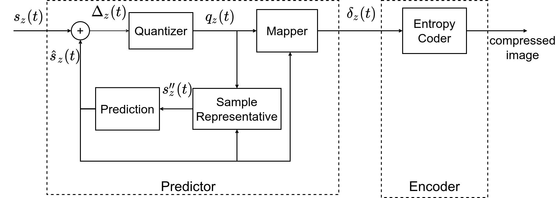
The predictor uses a low-complexity adaptive linear prediction method to predict the value of each sample based on the values of nearby samples in a small three-dimensional neighborhood. Prediction can be performed causally in a single pass through the image, making use of an adaptively weighted prediction algorithm. Since the original input samples will not be available to the decompressor due to lossy compression, the predictor performs calculations based on sample representatives instead.
Besides using sample representatives, the predictor in Issue 2 also differs from Issue 1 in that each prediction residual , that is, the difference between the predicted and actual sample values, is quantized using a uniform quantizer. The quantizer step size can be controlled via an absolute error limit (so that samples can be reconstructed with a user-specified error bound) and/or a relative error limit (so that samples predicted to have smaller magnitude can be reconstructed with lower error). Lossless compression in a band is obtained by setting the absolute error limit to zero. The quantized prediction residual is then mapped to an unsigned integer mapped quantizer index . These mapped quantizer indices make up the output of the predictor.
The Encoder receives those mapped quantizer indices from the Predictor and encodes them using a family of codes. The Standard describes three possible Encoder options, the Sample Adaptive Encoder, Block-Adaptive Encoder and Hybrid Entropy Coder. The CCSDS-120.2-G-2 Informational Report [3] includes detailed benchmarks of the encoders and highlights that even though the Hybrid Entropy Coder is the more complex encoder option, it is capable of improved compression performance for both lossless and near-lossless compression for well-chosen parameters. A comprehensive review of the Standard can also be found at [8].
II-B Hybrid Entropy Encoding Algorithm
The Hybrid Entropy Coder is a modified version of the one originally used by the FLEX entropy coder. It includes codes equivalent to the length-limited Golomb Power-of-2 (GPO2) codes (i.e. Golomb codes with parameters that are powers of 2, also known as Golomb-Rice codes [3, p. 3-15]) used by the Sample-Adaptive encoder, but extended with an additional 16 variable-to-variable length low-entropy codes. During encoding it adaptively switches between these two coding methods on a sample-by-sample basis based on code selection statistics. A single output codeword from a low-entropy code may encode multiple samples, which allows obtaining lower compression data rates (under one bit-per-pixel) than those achievable by the Sample-Adaptive entropy coder.
The mapped quantizer indices, of dynamic range , from the Predictor’s output are the inputs of the encoder. The Coder maintains the Adaptive Code Selection Statistics (ACSS), a high-resolution accumulator, , and a counter . Based on the ratio of these variables, the running is encoded with a high entropy or a low entropy code.
Initially when , both variables are initialized, and the first sample of every band, , is emitted uncompressed. For the rest of the encoding process, both variables are updated before coding the sample and rescaled when the counter saturates (indicated by the rescaling factor ), as shown in (1) and (2). After rescaling, the most significant value of is emitted to enable recalculation of the accumulator during the decoding process.
| (1) |
| (2) |
In equation (3), the choice of coder is represented by the high/low entropy flag (), where is a constant provided by the standard. When the flag is set, the current sample shall be encoded with a high entropy code, otherwise with a low entropy code.
| (3) |
Each high entropy sample is then encoded by a Reverse Length-Limited Golomb Power-of-2 (RLL-GPO2) code. Each code is identified by a code index , being the largest positive integer satisfying
| (4) |
| (5) |
The RLL-GPO2 codeword for the high entropy sample , is defined as follows:
-
a)
if , where is the maximum unary length, then consists of the least significant bits of the binary representation of , followed by a ‘one’, followed by ‘zeros’
-
b)
otherwise, consists of the -bit binary representation of followed by ‘zeros’.
Low entropy samples are encoded using one of 16 variable-to-variable length family of codes. The code index of the low entropy code to be used for encoding the low entropy sample is the largest positive satisfying
| (6) |
where are constants provided by the standard and is used in (5).
For each code a prefix of previously input samples is maintained. When a sample is processed, a symbol is added to the corresponding prefix. The standard defines a list of complete prefixes for each code. When a code’s prefix matches a complete prefix, then a unique codeword corresponding to that sequence of symbols is emitted and the prefix is cleared for this code .
The complete prefixes of any low entropy code , can only contain samples satisfying , where are constant symbol limits provided by the standard. When a sample exceeds this limitation, then is emitted, and an escape symbol (here represented as ) is added to the code’s prefix. The addition of the escape symbol, completes the prefix and the corresponding codeword is emitted. Therefore in this case an RLL-GPO2 codeword is followed by a low entropy codeword. The input symbol selection can be summarized as
| (7) |
III Introduced Architecture
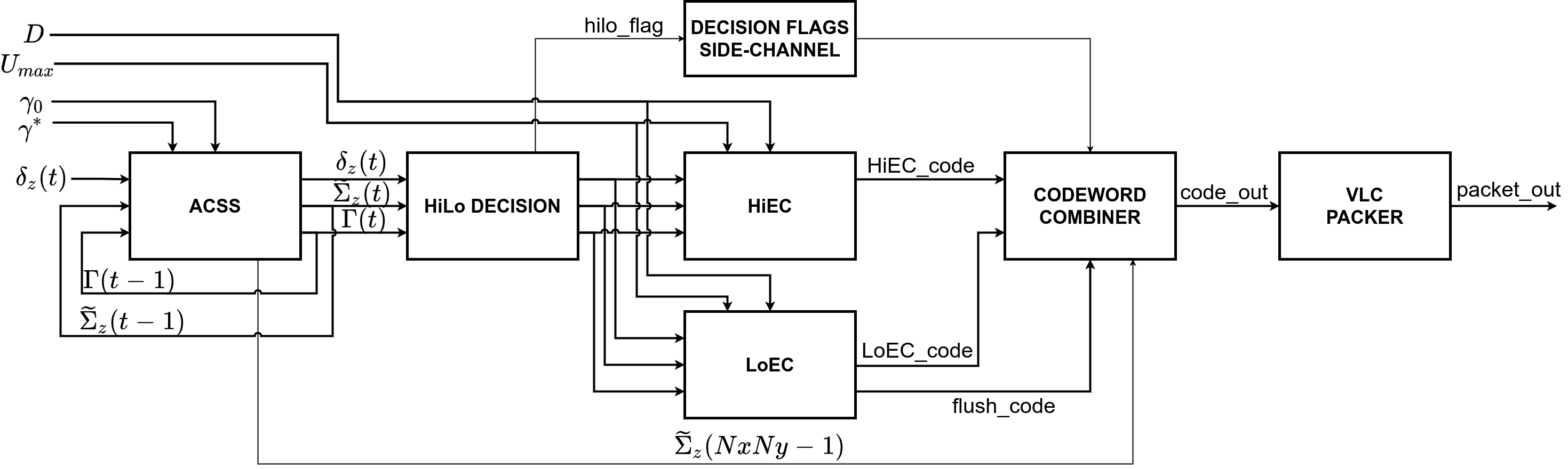
The Hybrid Entropy Coder is designed as an IP core described in technology agnostic VHDL RTL. However, technology specific blocks (e.g. DSP48E blocks in Xilinx FPGAs) are used by inference, as well as, generic usage for memory technology mapping between inference and vendor specific memory cells. The encoder operates in the BIP ordering to be matched with a lossless predictor in BIP order (e.g [9]), however, it can be modified to match specific instrument sensors and mission requirements, with different pixel order (BIL and BSQ). The top-level block diagram of the proposed Hybrid Entropy Coder architecture implemented as an IP core is shown in Fig. 2.
The IP Core interfaces using AXI4-Stream based I/O, supporting flow control using the protocol handshake (tvalid and tready signals). Internally, each encoder sub-unit, as shown in Fig. 2, is pipelined using a systolic latency insensitive design pattern, with elastic buffers [10] as pipeline registers. The elastic buffers use AXI4-Stream handshaking and allow for full throughput (1 cycle/sample) when neither source or sink are stalling. This design pattern avoids additional controllers for flow control, or superfluous buffering to manage sink side stalls. At the same time it facilitates Unit testing, by having consistent, verified interfaces in internal components on which testbench bus functional models attach with a consistent protocol.
The Hybrid Entropy Coder comprises of six pipelined components at the top level, which are:
-
1.
Adaptive Code Selection Statistics (ACSS) Unit
-
2.
High/Low (HiLo) Entropy Decision Unit
-
3.
High Entropy Coder (HiEC) Unit
-
4.
Low Entropy Coder (LoEC) Unit
-
5.
Codeword Combiner Unit and
-
6.
Variable Length Code (VLC) Packer Unit
III-A Design Considerations for Hardware Implementation
Using the latency insensitive design pattern, feed-forward processing paths are further pipelined to decrease logic path lengths and increase achievable frequency. However, processing feedback loops imply a total number of delay cycles equal to the pipeline registers in the loop, which if exceeded, limits performance in terms of cycles/sample processed. This creates a pipeline depth versus critical path (achievable Fmax) trade-off to be considered in these feedback loops. In this context, two components stand out in complexity, the ACSS unit, and the LoEC unit, which contain such feedback loops.
The ACSS unit contains a feedback loop in the update of and . Initializing and computing this update depending on previously computed values (, ), is handled by a Loop Controller module. In this unit, for BIP and BIL order the feedback datapath delay is commonly larger than the pipeline depth ( clock cycles), therefore the loop does not cause a performance degradation in terms of samples-per-cycle processed, unless the number of bands is extremely small. For BSQ order, the feedback datapath comprises of exactly one clock cycle delay, regardless of the number of bands.
The LoEC unit contains a loop where the input codeword in a code-table lookup operation, depends on the output of previous lookups of the same code-table.
III-B Adaptive Code Selection Statistics Unit
The Adaptive Selection Statistics (ACSS) Unit maintains and updates the accumulator , and counter , values according to equations (1) and (2), supplying them to the downstream units.
Both variables are updated when a new, , enters the encoder and rescaled when the counter reaches the value of the parameter. Under BSQ ordering one accumulator and one counter would be required. Under BIL ordering, the same elements and resources are required for each spectral band, which is accumulators and counter values. Under BIP ordering accumulator values and a single counter value are required.
For our BIP implementation, the current values of accumulator and counter, and , are computed using their previous values, and respectively, creating a dependency. To resolve it, values of for all bands are stored in a FIFO queue of depth at least equal to the number of bands, also acting as a delay buffer for the value of , taking advantage of the interleaved processing between the spectral bands. The feed-forward path of the loop is comprised of 2 pipeline stages, and , therefore the dependency is not violated.
A a similar architecture is estimated for the BIL implementation as well. In that case accumulator values would be stored in the FIFO queue at the end of every line of every band. In a BSQ architecture, the FIFO queue would not be included in the feedback datapath, acting only as a buffer for values at the and of every band in order to be emptied during the construction of the compressed image-tail. Finally, Loop Controller logic would be modified to meet each orders handshake requirements.
Code Statistics calculation is architecturally very similar to the Sample Adaptive Coder of [2], therefore an indicative implementation would be close in required resources as in [11],[12],[13], with the exception of the BSQ order, where the FIFO queue of depth would still be in use for storing for the compressed image-tail.
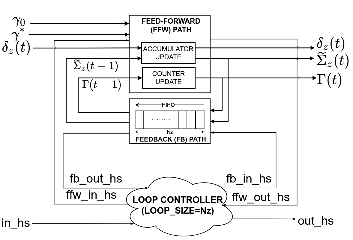
The top-level architecture of the ACSS unit is shown in Fig. 3. Signals with the “_hs” suffix represent handshaking signals, shown in a simplified ready/valid notation. As a whole, the ACSS unit receives a mapped quantizer index, (of bits) input and produces (of bits), (of bits), and certain flags used for codeword selection downstream. The unit consists of a feed-forward path which updates and and a feedback path, which comprises a queue storing previous values, returning them as to the feed-forward path.
Also, for the construction of the compressed image-tail, additional logic is introduced, not shown for clarity, that activates on assertion of the end of image flag, in order to extract and output the final values of from the feedback queue.
III-B1 Loop Controller
The Loop Controller is a generic IIR (Infinite Impulse Response) filter flow controller with an arbitrary pipelining depth in the feed-forward and feedback paths defined as RTL generics. There is a feed-forward pipelined path with pipeline registers and a feedback path with delay registers. The filter executes a function between the incoming samples and the feedback samples, for example
| (8) |
where is the feedback dependency of the loop.
The loop controller ensures that only up to samples can traverse the filter by manipulating the handshaking signals at the inputs and outputs of the feed-forward and feedback paths. If is less or equal than the total pipeline stages of the filter (), then the loop controller inserts stall cycles in the loop, in order to not violate the data dependency, limiting data throughput to samples/cycle. Otherwise, the filter operates in a constant data rate of 1 sample/cycle.
For the Hybrid Entropy Coder, the filter is described by (Equation 1). For the BIP order, the same equation can be re-written to resemble (Equation 8) as
with pipeline registers in the feed-forward path and delay registers on the feedback path. In case of , stall cycles would be introduced by the loop controller, limiting throughput to samples/cycle, but this is a highly unlikely use-case, since there are no multispectral (or hyperspectral) images with such low number of bands (multispectral typically refers to 3 up to 15 bands).
III-C High/Low Entropy Decision Unit
The design of this unit revolves around the multiplication between and the threshold constant as shown in (Equation 3). Constant is not a power of 2, thus embedded multiplier blocks, should be used depending on the FPGA technology. When targeting Xilinx technology, a Xilinx DSP48E2 Slice is used to perform the multiplication operation, registering both inputs and the product with the internal DSP48E2 pipeline registers. After the product is calculated a comparison follows that determines the encoder choice. A binary high/low(hilo) flag signals this decision, and is later used in the Codeword Combiner unit.
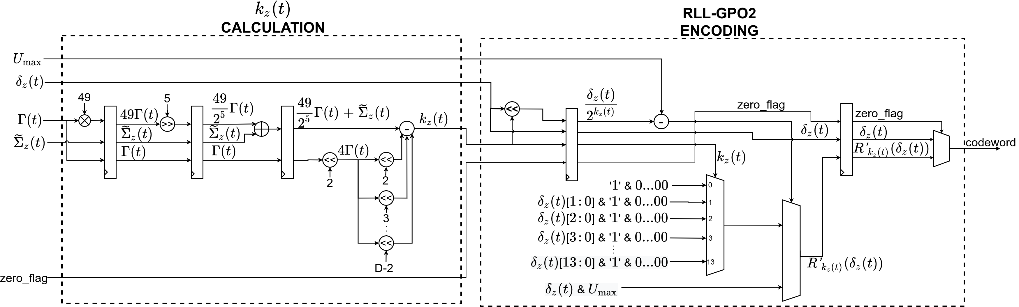
III-D High Entropy Coder Unit
In the High Entropy Coder (HiEC) unit is encoded with a “high entropy” RLL-GPO2 codeword. The HiEC unit (Fig. 4) comprises two sub-modules, the 3-stage pipelined Calculation module and the 2-stage pipelined RLL-GPO2 Encoding module. The former calculates the code index in bits as described in equations (4) and (5), while the latter calculates the RLL-GPO2 codeword in bits.
The unit receives and the code statistics and , along with and the zero flag (), and produces an RLL-GPO2 code along with its size in bits, producing 1 sample (codeword and code-size pair) per cycle.
III-E Low Entropy Coder Unit
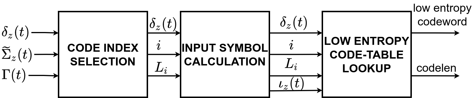
The Low Entropy Coder (LoEC) unit is responsible for emitting output codewords from the low entropy code-tables, by combining multiple input symbols in a single output codeword. The encoding procedure is implemented by three sub-units as shown in Fig. 5.
First, the code table index is selected by Code Index Selection unit, followed by the determination of the input symbol in Input Symbol Calculation unit. A series of input symbols for a certain , is used to search for a matching input codeword at the selected code-table. If one is found, the corresponding output codeword is emitted as the low entropy codeword along with its respective code-length. This procedure is performed by the Low Entropy Code-Tables Lookup unit. Finally, additional logic is implemented to extract flush codes from the 16 flush code-tables during the construction of the compressed image tail, signaled by an end-of-image flag.
III-E1 Code Index Selection & Input Symbol Calculation
The Code Index Selection unit selects the code-table index , which will be selected for lookup. It receives and statistics and as inputs and emits the code index and input symbol limit , as outputs, where is the largest code index satisfying (Equation 6).
To perform the multiplications, where are not powers-of-two, embedded multiplier blocks are used (e.g. 3-stage pipelined DSP48E2 Slices in Xilinx technology). All 16 multiplications are performed in parallel, and a comparison scheme selects the code index and input symbol limit.
The Input Symbol Calculation unit determines the input symbol, to be used for the code-table lookup as described in (Equation 7).
III-E2 Low Entropy Code-Table Lookup
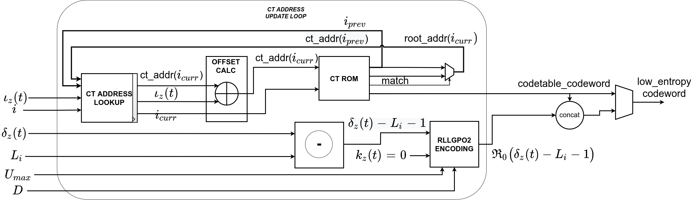
The Low Entropy Code-Table Lookup unit is the most complex unit and the primary performance bottleneck of the design. The unit contains two parallel data paths. The first path provides the low entropy codeword as a lookup to the selected code-table, while the second path calculates the RLL-GPO2 codeword, , when the input symbol is the escape symbol. The two codewords are concatenated, and a multiplexer selects either the single low entropy codeword, or the concatenated RLL-GPO2 codeword with the low entropy codeword.
Low Entropy Code-Tables ROM
A major design consideration is implementing the 16 low entropy code-tables and flush-tables efficiently. Taking advantage of the code-table tree structure, we adopt the representation of them in Code-Table ROMs for efficient lookups introduced for the first time in [7]. The structure used to represent the code and flush-tables resembles a prefix-free Trie data structure. The tree root is the “null” sequence while every child-node is connected to its parent with an edge representing an input symbol. Terminal nodes are output codewords and non-terminal nodes are flush codewords. A sequence of input symbols that leads to a terminal leaf node during encoding, causes a match codeword to be output. To map this sequence to ROM addresses, a model of the Code-Table ROMs was developed in software to appropriately order the code-table contents to allow lookup via address increments.
If input samples are exhausted before the tree for a code-table is fully traversed, then a flush codeword is emitted. Such codewords correspond to each non-terminal tree node and form part of the compressed image tail, which is emitted when sample encoding has finished. The Code-Table ROMs are looked-up with the last stored address of each tree in sequence of increasing code index, and the corresponding flush codeword is emitted, either from an intermediate node or from the tree’s root address.
To demonstrate, a similar but smaller code and flush-table are, along with the corresponding tree shown in Table I. This code-table is transformed for efficient lookups into the code-table ROM shown at the lower part of the table, each cell containing a tuple that corresponds to a tree node. The first tuple element represents the node’s parent flush codeword. In terminal nodes the second tuple element contains its output codeword. Otherwise, non-terminal nodes contain an offset which lead to the next node in the tree walk, when added to the incoming input symbol. The ROM contents are produced by representing each code-table with a Trie in software and then traversing it breadth-first, to produce appropriate pointer offsets for all possible walks from the root to the terminal nodes.
To implement the code-table ROM scheme, we store 16 ROM address pointers, in the CT_ADDRESS_LOOKUP memory shown in Fig. 6. Incoming symbols are added to the previous pointer for their corresponding code index to form a ROM address. When an escape symbol appears, a codeword emission is guaranteed from the selected code-table and the ROM address is reset to the root address. After the image is fully encoded, additional logic handles flush codewords for the image tail construction.
Low Entropy Feedback Loop
Low Entropy feedback loop is implemented as shown in Fig. 6. The selected code-table address is read from the CT_ADDRESS_LOOKUP registers and updated by adding the current input symbol. Then it is used for reading the code-table ROM (CT_ROM) and finally is written back to the registers.
In addition to the low entropy codeword, whenever the input symbol is the escape symbol, an additional RLL-GPO2 codeword for is produced by this unit. Therefore there are two output codewords corresponding to a single input.
The code-table address update procedure is performed in a single clock cycle providing full-throughput of one sample/cycle. The critical path of the design is also located in the feedback loop and defines the maximum achievable frequency.
III-F Codeword Combiner Unit & Variable Length Code Packer Unit
Depending on the HiLo decision flag and certain other flags, Code Combiner unit emits the appropriate codeword into the Variable Length Code (VLC) Packer’s input, which produces fixed 64-bit packets. In the case of a low entropy codeword, if the input symbol is the escape symbol, then the high entropy codeword must precede the low entropy code-table output codeword, meaning that there are two codewords to forward to the VLC packer corresponding to the same input sample. Also, whenever rescales, the least significant bit of is emitted to the bitstream for decoding purposes, meaning that it should precede the current codeword output.
The Codeword Combiner unit handles those special cases using flags produced throughout the encoding to provide the required output codewords to the VLC packer, as well as handling the sequence of outputs that constitute the compressed image tail.
After the Codeword Combiner unit has extracted the appropriate codeword, the Variable Length Code (VLC) Packer unit accepts variable-length codewords as inputs along with their length, and packs them into a 64-bit packets comprising the final bitstream. This component is re-used from previous work in [9] and is capable of operating in high data rates.
IV Experimental Results
The proposed CCSDS-123.0-B-2 Hybrid Entropy Coder architecture implemented as an IP core was verified using simulation-based (RTL) and FPGA-in-the-loop (FIL) based verification to speed-up verification process on a ZedBoard FPGA development board against a software golden model in Python, developed and provided by Universitat Autònoma de Barcelona (UAB).
The proposed architecture is implemented with the encoder parameters (Table III) defining the image dimensions (, , ), sample dynamic range (), Unary Length limit (), Initial Count Exponent () and the Rescaling Counter Size (). The encoder can be configured with run-time configurable parameters through a memory-mapped register interface, while VHDL generics are used to constrain the parameters’ maximum allowable range. Using as an example, at netlist generation time (compile-time) a VHDL generic g_Nx_max sets the maximum usable number of image columns and then at run-time through the configuration interface, this instance of the IP Core can be configured for values of to compress images with . This feature allows tailoring to optimize the design by minimizing resource utilization or increasing achievable frequency, at the expense of increased complexity in the RTL architecture and design. In all cases, the generics should not get values that exceed the maximum allowed value of the corresponding parameter as defined by the Standard [1].
IV-A Design Verification
The Hybrid Entropy Coder design was verified using simulation-based verification at VHDL RTL with Mentor Questa against the software golden model to ensure functional coverage of all corner cases and also targeting high VHDL code coverage (statement, branch, FSM and condition). The testing framework is based on the VUnit [14] Python testing framework and a set of python scripts. Test campaigns comprising of different images, compile time (generics) and run-time (compression) parameters are described in test files in this framework. The test scripts interpret the parameters to invoke the golden compressor binary to produce the verification data. Then, a testbench implemented as pass/fail test instrumented with VUnit is invoked with the Questa simulator with automatic checking comparing with golden responses.
A comprehensive test suite exercising all combinations of the encoder’s parameters (,,) was used to verify functional correctness. Finally, tests incorporating full images from AVIRIS [15] and AVIRIS-NG [16] image sets and synthetic images to debug corner case scenarios were applied to verify the encoder against realistic use-case scenarios.
More comprehensive verification was performed using FPGA-in-the-loop (FIL) techniques on a ZedBoard FPGA development board hosting a Xilinx Zynq-7000 SoC FPGA device, also leveraging the ARM embedded processor. For the purposes of FIL verification, several hyperspectral test cubes including synthetic and random test images and using multiple configurations were transferred to the board and the compressed images was received from the board using a JTAG-to-AXI interface.
IV-B Design Implementation
The CCSDS-123.0-B-2 Hybrid Entropy Coder was implemented targeting Xilinx Kintex-Ultrascale technology (XCKU040-2FFVA1156E FPGA) and is therefore directly transferable (in terms of implementation results), to the Xilinx Radiation Tolerant XQRKU060 FPGA. Implementation on the target device was performed using a configuration for the AVIRIS (680512224, 16bpppb), AVIRIS-NG (640512432, 14bpppb) hyperspectral instruments, which are typical hyperspectral sensors and the standard benchmark in the literature.
Table II presents implementation (Place & Route, Timing Analysis) results for the Kintex Ultrascale FPGA using Xilinx Vivado 2020.2. The implementation parameters used are those suggested as defaults in [17] and [3] (, ). For more accurate implementation results, the generic parameters defining the maximum allowed values of encoder inputs, are set to be equal to the exact input parameter value.
The proposed architecture achieves a constant throughput of 305 MSamples/sec operating at 305 MHz while the FPGA resource footprint is kept low. The power consumption is reported for the whole FPGA including SpaceFibre interface IP cores and the Kintex Ultrascale device GTH transceivers.
Design’s data rate throughput can be estimated by the ratio between total image samples and total clock cycles, needed for a complete encoding.
| (9) |
The total number of samples are divided by the total number of clock cycles. Here, , are the initial cycles required for the pipeline to fill up and for the header generation. In addition to these initial cycles, there are samples processed in one cycle each and the cycles consumed for the image tail creation, which are the extraction of 16 flush-codewords followed by accumulator values also processed in one cycle each. Finally, , is the number of escape symbols that force the low entropy coder to produce an additional RLL-GPO2 codeword to the low entropy code-table codeword, requiring an additional clock cycle in encoding.
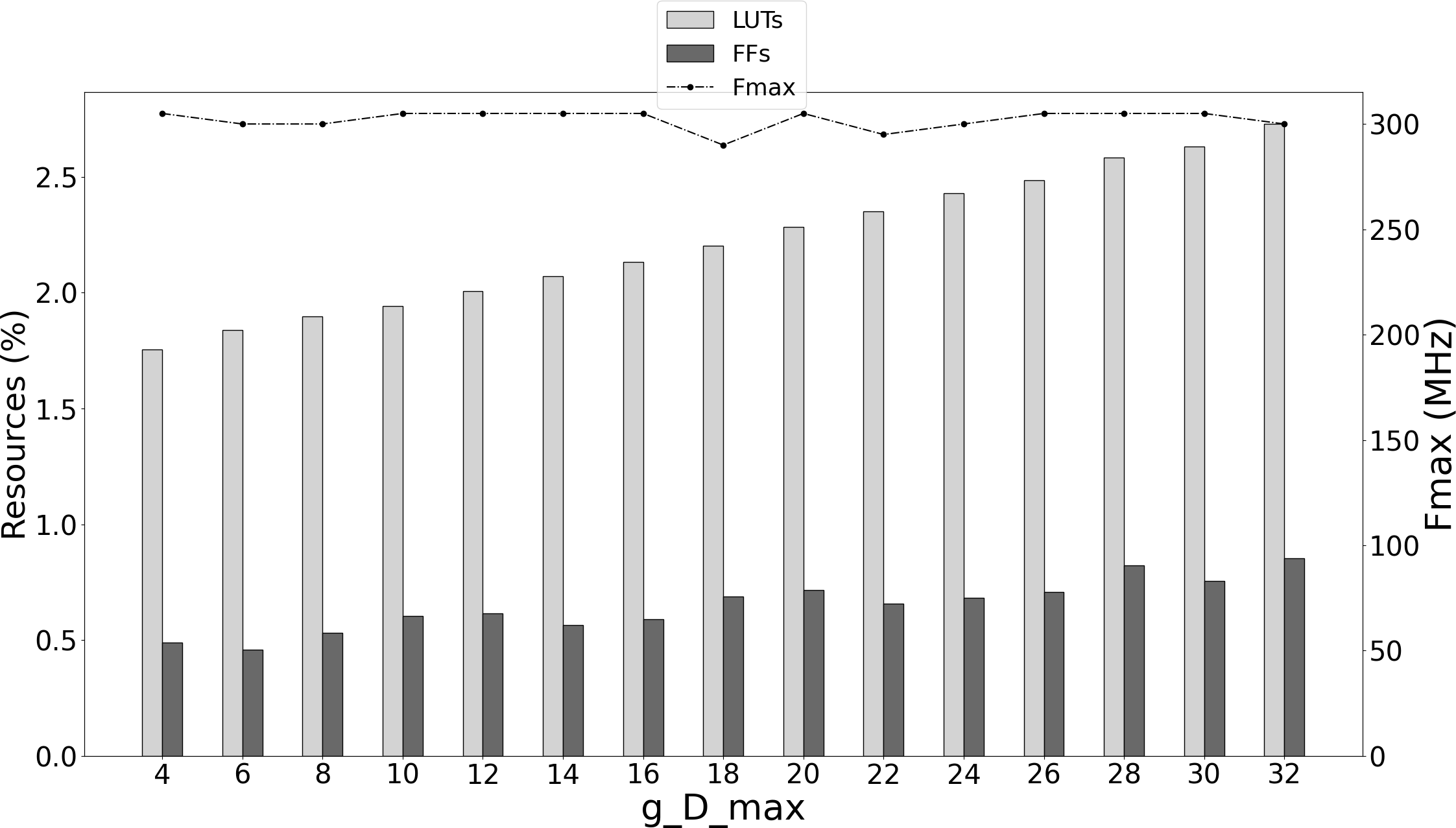
Fig. 7 presents the resource usage and maximum frequency after Place & Route for the generic-configurable parameter g_D_max. Maximum frequency of the IP Core is slightly influenced by the increase of g_D_max estimated between 290 MHz and 305 MHz for g_D_max = 2,4,6,…,32, while resources tend to increase as data-path width is close relating to g_D_max.
The throughput performance is stable, providing a constant data rate of 1 sample/cycle which does not depend on the hyperspectral image data statistics and is not degraded when high Absolute Error Limit Constants are configured leading to a large number of low entropy encoded samples as in our preliminary work[7]. The critical path of the design is located in the low entropy coder’s feedback loop datapath which determines the maximum operational frequency. The code-table ROM component included in this feedback loop path is implemented using asynchronous distributed RAM (LUTRAM), instead of BRAM in order to avoid the RAW hazard of LoEC loop, resulting in increased LUT usage.
IV-C Design Validation
The CCSDS-123.0-B-2 Hybrid Entropy Coder’s validation and demonstration set-up is built around SpaceFibre (ECSS-E-ST-50-11C) test equipment, provided by STAR-Dundee, to interface the Xilinx KCU105 development board and match standard space deployment. SpaceFibre is a very high-speed (5 Gbit/s) serial link and network technology, designed specifically for use on board spacecraft.
The CCSDS-123.0-B-2 Hybrid Entropy Coder validation and demonstrator set-up includes a standard PC emulating Electronic Ground Support Equipment (EGSE). The EGSE PC hosts a STAR-Ultra PCIe board which is connected to the KCU105 development board using QSFP to SFP+ cable assembly. SpaceFibre interface VHDL IP Cores are also implemented in the XCKU040 FPGA hosted in KCU105 board to provide AXI4-Stream interface with the CCSDS-123.0-B-2 Hybrid Entropy Coder IP Core data inputs and compressed output over a singe data Virtual Channel (VC). A single lane SpaceFibre link able to provide 6.25 Gbps (effective 5.0 Gbps) data-rate is sufficient for the validation and demonstration of the CCSDS-123.0-B-2 Hybrid Entropy Coder.
A large set of test images from the CCSDS corpus of images [18] along with several images from the PRISMA Hyperspectral mission [19] launched March 2019, with multiple compression configurations was applied by the EGSE PC for the validation of the Hybrid Entropy Coder. Table IV displays the achieved throughput for some notable images used in the validation process. These figures were validated by SpaceFibre link analyser software installed in the EGSE PC along with performance counters instrumenting the IP Core in the XCKU040 FPGA. Images were compressed with in lossless () and near-lossless () mode, always operating at 1 sample-per-cycle efficiency in agreement with the data rate estimation of Equation 9. The presented CCSDS-123.0-B-2 Hybrid Entropy Coder IP Core achieved 305 MSamples/sec (4.88 Gbps) throughput performance.
V Comparison With Previous Work
The previous issue of the standard, CCSDS-123.0-B-1, describes only lossless compression and is considered a mature solution for on-board hyperspectral compression. Issue 2, shares many implementation similarities to Issue 1, regarding the lossless compression option, therefore implementation of Issue 1 are considered comparable prior work. Multiple implementations have been presented in the literature designed for various trade-offs and devices such as FPGAs and GPUs, as well as Systems-on-a-chip (SoC). SHyLoC 1.0 [11] and SHyLoC 2.0 [12] implementations, available at the European Space Agency (ESA) IP Cores library to be licensed for space missions, research and/or commercial use, under specific conditions, provide a feature complete implementation of CCSDS-123.0-B-1 and CCSDS-121.0-B-2 algorithms, as a technology agnostic IP Core suitable for FPGA and ASIC technologies. Moreover, SHyLoC IP Cores provide wide and versatile parameterization and configuration options enabling reduced complexity and footprint when dealing with FPGA devices with a limited amount of resources. Other implementations provide high-throughput by using a either a single compression engine, [9], [23], [24], [25] and leveraging the interleaved processing of BIP pixel order format that enables deep pipelining presented for the first time in [26] or by exploiting the CCSDS-123.0 image segmentation and task-level parallelism along with Commercial Off-the Shelf (COTS) FPGA SoC technologies [27], [28],[29], achieving state-of-the-art throughput performance [30]. Implementation on GPU devices [31],[32],[33] utilize GPUs and heterogeneous CPU and GPU systems to parallelize the CCSDS-123.0-B-1 standard by exploiting image segmentation and task-level parallelism, achieving very high-throughput, but higher energy consumption when compared to FPGA implementations.
Due to the recent release of Issue 2, there are few known implementations of CCSDS-123.0-B-2 in literature to date, none of which involved the VHDL RTL implementation of the Hybrid Entropy Coder or the full CCSDS-123.0-B-2 standard.
In [34] the authors present a parallel implementation in software of the near-lossless CCSDS-123.0-B-2 standard for the evaluation of the RC64 many-core rad-hard processor [35]. However, they implement only the Sample Adaptive Entropy Coder while the Hybrid Entropy Coder was not considered due to implementation challenges related to throughput performance. This parallelization scheme achieves high speed-up when all 64 cores are used, with maximum throughput of 0.45 MSamples/sec, and limited performance when there are idle cores.
In [36], the authors propose parallel implementations of both Issue 1 and Issue 2 of CCSDS-123.0-B-2 in software with OpenMP targeting different space qualified CPUs (i.e. GR740, LS1046). Their work suggests ways of splitting data and assigning jobs among the available CPU cores, for both lossless and near-lossless predictor and hybrid entropy encoder.
The Fast Lossless Extended (FLEX) algorithm [20],[21],[22] is the algorithmic basis for CCSDS-123.0-B-2 and the Hybrid Entropy Coder is an extension of the FLEX’s original hybrid entropy coder, therefore FLEX implementations can be considered for comparison purposes. Experimental results for the FLEX entropy coder targeting the Virtex 5 FX130T FPGA technology reach a maximum frequency of 168.8 MHz and a throughput of 24 MSamples/sec using (7 cycles/sample). For the whole FLEX compressor a throughput of 3.4 MSamples/sec was achieved at 82.5 MHz maximum frequency (24 cycles/sample). Although a direct comparison with FLEX entropy coder in terms of maximum frequency is not appropriate because this paper considers a next-generation space-grade FPGA platform, the proposed Hybrid Entropy Coder architecture achieves 7 times higher throughput performance in terms of samples/cycle. Table V summarizes the comparison of RTL implementation of FLEX Hybrid Entropy Coder with the presented work.
The first, full implementation of the CCSDS-123.0-B-2 standard, although using High-Level Synthesis (HLS), was presented in [37]. The CCSDS-123.0-B-2 compressor developed for the ESA CHIME space mission includes a High-Level Synthesis (HLS) implementation of the near-lossless predictor and re-uses the VHDL RTL implementation of the Block-Adaptive encoder as implemented for the SHyLoC [11] IP Core. The Hybrid Entropy Encoder was not considered, and thus, comparisons are not appropriate. The compressor in [37] meets CHIME mission requirements of data rate up to 2 Gbps (@16bppb, 125 MHz), with the HLS-generated near-lossless Predictor requiring more than 1 cycles/sample, which the authors plan to improve in future implementations in VHDL RTL.
Conclusion
In this paper, we introduced an efficient architecture and a high-throughput hardware implementation of the CCSDS-123.0-B-2 Hybrid Entropy Coder. The introduced architecture exploits the systolic design pattern to provide modularity and latency insensitivity in a deep and elastic pipeline, as well as an innovative approach on the Low Entropy Coder’s codetable lookup design, and achieves a constant high-throughput implementation in space-grade SRAM FPGA technology ( 305 MSamples/s operating at 1 sample/cycle) with a small FPGA resource footprint. The introduced architecture is validated and demonstrated on a commercially available Xilinx KCU105 development board hosting a Xilinx Kintex Ultrascale XCKU040 SRAM FPGA, and thus, is directly transferable to the Xilinx Radiation Tolerant Kintex UltraScale XQRKU060 space-grade devices for space deployments. Moreover, state-of-the-art SpaceFibre (ECSS-E-ST-50-11C) interface and test equipment were used in the validation platform to match space deployment. To the best of our knowledge, this is the first published fully-compliant architecture and high-throughput implementation of the CCSDS-123.0-B-2 Hybrid Entropy Coder, also targeting space-grade FPGA technology.
Acknowledgment
We would like to thank Ian Blanes and Joan Serra-Sagristà from Universitat Autònoma de Barcelona (UAB) for providing the software golden model for the CCSDS-123.0-B-2 algorithm. Part of this research has received funding from the Hellenic Foundation for Research and Innovation (HFRI) and the General Secretariat for Research and Technology (GSRT) under the 1st call for H.F.R.I. Research Projects for the support of Post-doctoral Researchers under grant agreement No 990 and part of it has received funding from the European Union’s Horizon 2020 research and innovation programme under grant agreement No 776151.
References
- [1] Low-Complexity Lossless and near-Lossless Multispectral and Hyperspectral Image Compression, Issue 2 - Recomended Standard (Blue Book), CCSDS-123.0-B-2, Consultative Committee for Space Data Systems (CCSDS).
- [2] Lossless Multispectral and Hyperspectral Image Compression, Issue 1 - Recomended Standard (Blue Book), CCSDS-123.0-B-1, Consultative Committee for Space Data Systems (CCSDS).
- [3] Low-Complexity Lossless and near-Lossless Multispectral and Hyperspectral Image Compression - Draft Informational Report, Consultative Committee for Space Data Systems (CCSDS).
- [4] M. Klimesh, “Low-Complexity Lossless Compression of Hyperspectral Imagery via Adaptive Filtering,” The Interplanetary Network Progress Report, vol. 42, no. 163, p. 10, 11 2005.
- [5] ——, “Low-Complexity Adaptive Lossless Compression of Hyperspectral Imagery,” in Satellite Data Compression, Communications, and Archiving II, vol. 6300. International Society for Optics and Photonics, 9 2006, p. 63000N.
- [6] “Radiation Tolerant Kintex UltraScale XQRKU060 FPGA Data Sheet,” p. 101, 2020.
- [7] P. Chatziantoniou, A. Tsigkanos, and N. Kranitis, “A High-Performance RTL Implementation of the CCSDS-123.0-B-2 Hybrid Entropy Coder on a Space-Grade SRAM FPGA,” in 7th International Workshop on On-Board Payload Data Compression (OBPDC), 9 2020, p. 8.
- [8] M. Hernandez-Cabronero, A. B. Kiely, M. Klimesh, I. Blanes, J. Ligo, E. Magli, and J. Serra-Sagrista, “The CCSDS 123.0-B-2 Low-Complexity Lossless and Near-Lossless Multispectral and Hyperspectral Image Compression Standard: A comprehensive review,” IEEE Geoscience and Remote Sensing Magazine, pp. 0–0, 2021.
- [9] A. Tsigkanos, N. Kranitis, G. Theodorou, and A. Paschalis, “A 3.3 Gbps CCSDS 123.0-B-1 Multispectral & Hyperspectral Image Compression Hardware Accelerator on a Space-Grade SRAM FPGA,” IEEE Transactions on Emerging Topics in Computing, vol. 9, no. 1, pp. 90–103, 2021.
- [10] G. Dimitrakopoulos, A. Psarras, and I. Seitanidis, “Link-Level Flow Control and Buffering,” in Microarchitecture of Network-on-Chip Routers: A Designer’s Perspective, G. Dimitrakopoulos, A. Psarras, and I. Seitanidis, Eds. New York, NY: Springer, 2015, pp. 11–35.
- [11] L. Santos, A. Gómez, and R. Sarmiento, “Implementation of CCSDS Standards for Lossless Multispectral and Hyperspectral Satellite Image Compression,” IEEE Transactions on Aerospace and Electronic Systems, vol. 56, no. 2, pp. 1120–1138, 4 2020.
- [12] Y. Barrios, A. J. Sánchez, L. Santos, and R. Sarmiento, “SHyLoC 2.0: A Versatile Hardware Solution for On-Board Data and Hyperspectral Image Compression on Future Space Missions,” IEEE Access, vol. 8, pp. 54 269–54 287, 2020.
- [13] University of Las Palmas de Gran Canaria, “SHyLoC Product Datasheet,” Oct. 2017. [Online]. Available: https://amstel.estec.esa.int/tecedm/ipcores/SHyLoC_Datasheet_v1.0.pdf
- [14] L. Asplund and O. Kraigher, “VUnit: a test framework for HDL.” [Online]. Available: https://vunit.github.io/index.html
- [15] “AVIRIS - Airborne Visible / Infrared Imaging Spectrometer.” [Online]. Available: https://aviris.jpl.nasa.gov/
- [16] “AVIRIS-Next Generation.” [Online]. Available: https://avirisng.jpl.nasa.gov/index.html
- [17] I. Blanes, A. Kiely, M. Hernández-Cabronero, and J. Serra-Sagristá, “Performance Impact of Parameter Tuning on the CCSDS-123.0-B-2 Low-Complexity Lossless and Near-Lossless Multispectral and Hyperspectral Image Compression Standard,” Remote Sensing, vol. 11, no. 11, p. 1390, 1 2019.
- [18] “The Consultative Committee for Space Data Systems, Corpus of Hyperspectral and Multispectral images.” [Online]. Available: http://cwe.ccsds.org/sls/docs/sls-dc/123.0-B-Info/TestData
- [19] “ASI Prisma Products Specification Document Issue 2.3.” [Online]. Available: https://prisma.asi.it/missionselect/docs/PRISMA%20Product%20Specifications_Is2_3.pdf
- [20] D. Keymeulen et al., “FPGA Implementation of Space-Based Lossless and Lossy Multispectral and Hyperspectral Image Compression,” in 5th International Workshop on On-Board Payload Data Compression (OBPDC), September 2016.
- [21] ——, “High Performance Space Computing with System-on-Chip Instrument Avionics for Space-based Next Generation Imaging Spectrometers (NGIS),” in 2018 NASA/ESA Conference on Adaptive Hardware and Systems (AHS), Aug. 2018, pp. 33–36.
- [22] ——, “High Performance Space Data Acquisition and Compression with Embedded System-on-Chip Instrument Avionics for Space-based Next Generation Imaging Spectrometers (NGIS),” Proceedings of 27th Annual Single Event Effects (SEE) Symposium and Military and Aerospace Programmable Logic Devices (MAPLD) Workshop, p. 20, 2018.
- [23] A. Tsigkanos, N. Kranitis, and A. Paschalis, “CCSDS 123.0-B-1 Multispectral & Hyperspectral Image Compression Implementation on a Next-Generation Space-Grade SRAM FPGA,” in 6th International Workshop on On-Board Payload Data Compression (OBPDC), 9 2018, pp. 1–8.
- [24] D. Báscones, C. González, and D. Mozos, “FPGA Implementation of the CCSDS 1.2.3 Standard for Real-Time Hyperspectral Lossless Compression,” IEEE Journal of Selected Topics in Applied Earth Observations and Remote Sensing, vol. 11, no. 4, pp. 1158–1165, Apr. 2018.
- [25] J. Fjeldtvedt, M. Orlandić, and T. A. Johansen, “An Efficient Real-Time FPGA Implementation of the CCSDS-123 Compression Standard for Hyperspectral Images,” IEEE Journal of Selected Topics in Applied Earth Observations and Remote Sensing, vol. 11, no. 10, pp. 3841–3852, 10 2018.
- [26] G. Theodorou, N. Kranitis, A. Tsigkanos, and A. Paschalis, “High-Performance CCSDS-123.0-B-1 Multispectral and Hyperspectral Image Compression Implementation on a Space Grade SRAM FPGA,” in 5th International Workshop on On-Board Payload Data Compression (OBPDC), 9 2016, p. 8.
- [27] D. Báscones, C. González, and D. Mozos, “Parallel Implementation of the CCSDS 1.2.3 Standard for Hyperspectral Lossless Compression,” Remote Sensing, vol. 9, no. 10, p. 973, Oct. 2017.
- [28] A. Rodríguez, L. Santos, R. Sarmiento, and E. De La Torre, “Scalable Hardware-Based On-Board Processing for Run-Time Adaptive Lossless Hyperspectral Compression,” IEEE Access, vol. 7, pp. 10 644–10 652, 2019.
- [29] M. Orlandić, J. Fjeldtvedt, and T. A. Johansen, “A Parallel FPGA Implementation of the CCSDS-123 Compression Algorithm,” Remote Sensing, vol. 11, no. 6, p. 673, 1 2019.
- [30] A. Tsigkanos, N. Kranitis, D. Theodoropoulos, and A. Paschalis, “High-Performance COTS FPGA SoC for Parallel Hyperspectral Image Compression With CCSDS-123.0-B-1,” IEEE Transactions on Very Large Scale Integration (VLSI) Systems, vol. 28, no. 11, pp. 2397–2409, 11 2020.
- [31] O. Ferraz, V. Silva, and G. Falcao, “1.5GBIT/S 4.9W Hyperspectral Image Encoders on a Low-Power Parallel Heterogeneous Processing Platform,” in ICASSP 2020 - 2020 IEEE International Conference on Acoustics, Speech and Signal Processing (ICASSP), May 2020, pp. 1693–1697.
- [32] O. Ferraz, G. Falcao, and V. Silva, “Gbit/s Throughput Under 6.3-W Lossless Hyperspectral Image Compression on Parallel Embedded Devices,” IEEE Embedded Systems Letters, vol. 13, no. 1, pp. 13–16, Mar. 2021.
- [33] O. Ferraz, V. Silva, and G. Falcao, “Hyperspectral Parallel Image Compression on Edge GPUs,” Remote Sensing, vol. 13, no. 6, p. 1077, Jan. 2021.
- [34] P. López Cueva, R. Barrère, K. Eyssartier, and M. Bruno, “Evaluation of New Generation Rad-Hard Many-Core Architecture for Satellite Payload Applications,” in European Workshop on On-Board Data Procesing (OBDP2021), Jun. 2021.
- [35] R. Ginosar, P. Aviely, T. Israeli, and H. Meirov, “RC64: High performance rad-hard manycore,” in 2016 IEEE Aerospace Conference, Mar. 2016, pp. 1–9.
- [36] C. Trohin, L. Banu, A. Tomescu, and C. Padureanu, “Parallelization of Prediction and Encoding for Multispectral and Hyperspectral Images,” in 7th International Workshop on On-Board Payload Data Compression (OBPDC), Sep. 2020.
- [37] Y. Barrios, P. Rodriguez, A. Sanchez, M. I. González, L. Berrojo, and R. Sarmiento, “Implementation of cloud detection and processing algorithms and CCSDS-compliant hyperspectral image compression for CHIME mission,” in 7th International Workshop on On-Board Payload Data Compression (OBPDC), Sep. 2020.
![[Uncaptioned image]](/html/2205.04123/assets/paper_figures/authors/Chatziantoniou.png) |
Panagiotis Chatziantoniou received the B.Sc in Computer Engineering from the Computer Engineering and Informatics Department (CEID) of University of Patras (UoP), in 2006 and M.Sc in Computer Systems: Software and Hardware from the the Department of Informatics & Telecommunications of the National and Kapodistrian University of Athens (NKUA) at 2020. Currently, he is working towards his PhD degree at NKUA, Greece. He is a member of Digital Systems & Computer Architecture Laboratory (DSCAL) of NKUA. His research interests include hardware design on-board payload data processing systems, FPGA-based acceleration, dependable and reconfigurable computing and reliability. |
![[Uncaptioned image]](/html/2205.04123/assets/paper_figures/authors/Tsigkanos.png) |
Antonis Tsigkanos (M’17) received his Ph.D., M.Sc. from the Department of Informatics and Telecommunications, of the National and Kapodistrian University of Athens (NKUA), Greece and his B.Eng. degree from the Electrical and Computer Engineering School of the National Technical University of Athens (NTUA). Currently, he works as ASIC design engineer in the semiconductor industry, designing ultra Low power processors optimized for AI workloads and graphics. He has published multiple papers in peer reviewed transactions, journals, and conference proceedings. His research interests include on-board payload data processing systems, SoC design, reliability, deep learning accelerators and low power design. |
![[Uncaptioned image]](/html/2205.04123/assets/paper_figures/authors/Theodoropoulos.png) |
Dimitris Theodoropoulos (M’19) received the M.Sc. degree from the Department of Informatics and Telecommunications of the National and Kapodistrian University of Athens (NKUA), Greece, Athens, Greece, in 2015. He is serving as an active duty military officer for the Hellenic Air Force (HAF), with specialty and expertise on informatics and telecommunication systems. He is pursuing his PhD degree at the the NKUA, Greece and he is a member of the Digital Systems & Computer Architecture Laboratory (DSCAL) of NKUA. His scientific interests focus on the hardware design of onboard processing hardware systems for aerospace applications. |
![[Uncaptioned image]](/html/2205.04123/assets/paper_figures/authors/kranitis_BW.png) |
Nektarios Kranitis (Senior Member, IEEE) received the BSc degree in Physics from the Department of Physics, University of Patras, Patras, Greece, in 1997, and the PhD degree in Computer Science from the Department of Informatics and Telecommunications, of the National and Kapodistrian University of Athens (NKUA), Greece, in 2005 under Scholarship from the Institute of Informatics and Telecommunications, National Centre for Scientific Research (N.C.S.R.) “Demokritos”. He is currently an Associate Professor at the Department of Aerospace Science and Technology of NKUA, Greece. His research interests focus on on-board computers & data handling, onboard payload data processing systems, FPGA-based acceleration and dependable and reliable systems design. He has been involved in several R&D projects funded by ESA, EU and the Greek government as PI or senior researcher in onboard data systems technology. He has published more than 70 papers in peer reviewed transactions, journals and conference proceedings. Currently, there are more than 1500 citations that refer to his published work while his h-index is 20. He is a Senior member of the IEEE, the IEEE Aerospace and Electronic Systems Society (AESS) and the IEEE Computer Society (CS). |
![[Uncaptioned image]](/html/2205.04123/assets/paper_figures/authors/Paschalis_BW.png) |
Antonis Paschalis (M’97) received the B.Sc. degree in Physics, the M.Sc. degree in Electronic Automation, and the Ph.D. degree in Dependable Computers, under scholarship from NCSR “Demokritos”, all from the Department of Physics, National and Kapodistrian University of Athens (NKUA), Athens, Greece, in 1983, 1985, and 1987, respectively. He is a Professor with the Department of Informatics and Telecommunications, NKUA, and head of space upstream technology research group of Digital Systems and Computer Architecture Laboratory participating in ESA space missions. He has published over 160 papers (26 IEEE Transactions) and holds a U.S. patent. His current research interests include reconfigurable payload data processing units and high-speed IP cores for aerospace systems, VLSI design and testing, and dependable computer architecture. Currently, there are more than 2,600 citations that refer to his published material and his h-index is 29. Prof. Paschalis is a Golden Core Member of IEEE Computer Society. |