Reducing controls noise in gravitational wave detectors with interferometric local damping of suspended optics
Abstract
Control noise is a limiting factor in the low-frequency performance of the LIGO gravitational-wave detectors. In this paper we model the effects of using new sensors called HoQI s to control the suspension resonances. We show if we were to use HoQI s, instead of the standard shadow sensors, we can suppress resonance peaks up to tenfold more while simultaneously reducing the noise injected by the damping system. Through a cascade of effects this will reduce the resonant cross-coupling of the suspensions, allow for improved stability for feed-forward control, and result in improved sensitivity of the detectors in the Hz band. This analysis shows that improved local sensors such as HoQI s should be used in current and future detectors to improve low-frequency performance.
1 Introduction
Gravitational waves were predicted by Einstein’s Theory of General Relativity, and were first observed in 2015 GW150914 . Since then multiple events O21 ; O3 have been detected by the Advanced Laser Interferometer Gravitational-Wave Observatory (LIGO) AdvancedLigo and Advanced Virgo AdvancedVirgo interferometers. These interferometers precisely measure the Differential ARM length (DARM) changes of the long (3-4 km) arm cavities. Passing gravitational waves induce differential strain in the perpendicular arms, allowing interferometric detection.
The first detection of a binary neutron star inspiral BNS ; BNSMMS demonstrated the importance of gravitational wave detectors for multi-messenger astronomy. Gravitational wave detectors provide sky localization from triangulation with multiple detectors. Inspiral detection can provide early alerts for electromagnetic and particle observatories.
Improvements to sensitivity at Hz enable earlier detections, greater signal-to-noise ratios, and further astrophysical reach into space A+ . All events observed so far have been inspirals, where the frequency increases until the objects collide and merge. However, the signals have much longer duration at lower frequencies, with the time-until-merger proportional to . Improvements to low frequency sensitivity are therefore especially important for earlier detections and increasing the time in the measurement band, which in turn improves sky localisation 5hz .
One of the largest noise sources in earth-bound gravitational-wave detectors is ground vibration, which is ten orders of magnitude larger than the signal GW150914 and moves the optics of the interferometer. The LIGO observatory has seismic isolation systems consisting of cascaded passive QuadUpdate and active isolation ISI1 ; ISI2 to suppress this movement noise, and facilitate gravitational wave detection. Passive isolation is achieved through the use of pendula, and mass-spring-systems. Active isolation employs a blend of relative displacement and inertial sensors for feedback control of the passive isolation systems.
Despite the success of these isolation systems in reducing direct vibration coupling, Advanced LIGO’s low-frequency sensitivity is limited at Hz by ‘global control noise’ from the interferometer’s Alignment Sensing and Control (ASC) and the auxiliary Length Sensing and Control systems O33 .
Global controls keep the optics of the interferometer correctly placed and oriented relative to each other. Local controls, on the other hand, minimize the transfer of ground motion to an individual optic.
In this paper we analyse how improved local sensors and controls can improve performance in a manner that improves the performance and predictability for global controls. Suspension chains with better local damping produce a quieter, simpler, and more stable plant, thereby reducing noise that is associated with non-linear, bi-linear, and non-stationary couplings that cannot currently be suppressed in post-processing O3 ; MachineNoise .
There is a large and growing community of instrumentation development for 3G observatories (for a subset of proposed sensors and measurement methods see references DOSEM ; COLLETTE201572 ; intorev ; smetana2022compact ; Gerberding:15 ; Miller:12 ; https://doi.org/10.48550/arxiv.2111.14355 and inertial sensors https://doi.org/10.48550/arxiv.2204.04150 ; 10.1785/0120090136 ; ZHAO2020106959 ; 8336722 ; doi:10.1063/1.4881936 ; Kohlenbeck:2018eit ; Cooper_2022 ; Mow_Lowry_2019 ; VerticalInertial ; doi:10.1063/5.0047069 ; rohtua ; alma9920725267002321 ; Chang:20 ; RossThesis ; lfsvm ; doi:10.1063/1.4862816 ; DING2022113398 ; 0047069 ; Ubhi_2021 ; Korth_2016 ). In this paper we present a novel analysis of the projected quantitative effect of these instruments on the performance of a multi-stage suspension. This is the most detailed analysis of this kind. It includes the most important cross-couplings and all known input noise sources based on measurements from LIGO, and produces output metrics that are relevant for global interferometer controls. While there are currently no models that correctly predict the detector sensitivity based on local suspension performance, we qualitatively elaborate on the connection between local sensors and improved detector sensitivity at low frequencies. In particular, we show how local resonances below 3 Hz result in noise in the Hz region. Our results support the statement that improved damping is one of the elements required for breaking the ‘low-frequency wall’ (5hz, )
The MIMO suspension model used in this work is a modification of previous models that includes the design parameters for the new Big BeamSplitter Suspension (BBSS), which is the first Advanced LIGO suspension to receive a major upgrade APDR . Previous suspensions show excellent agreement between the MIMO model and measured transfer functions, with the exception of cross-couplings, which are not included in the stiffness matrix SimulationComparison . We include the state-space suspension model, the control filters, and scripts for generating plots as supplemental material.
2 Presented Opportunity: The LIGO A+ Big Beamsplitter Suspension
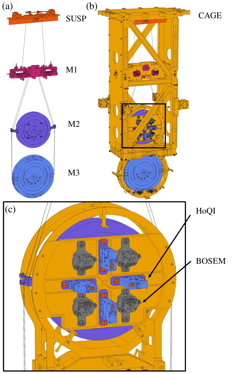
(a) the suspended masses; beamsplitter top mass (M1), beamsplitter intermediate mass (M2), beamsplitter optic (M3)that are mounted to the cage through the SUSP.
(b) the suspended masses together with the cage which is fixed to the ISI platform.
(c) detailed view showing the proposed sensor and actuator arrangement at M2, showing BOSEM s (used only for actuation) in the corners and HoQI s (only capable of sensing) along the vertical and horizontal axes.
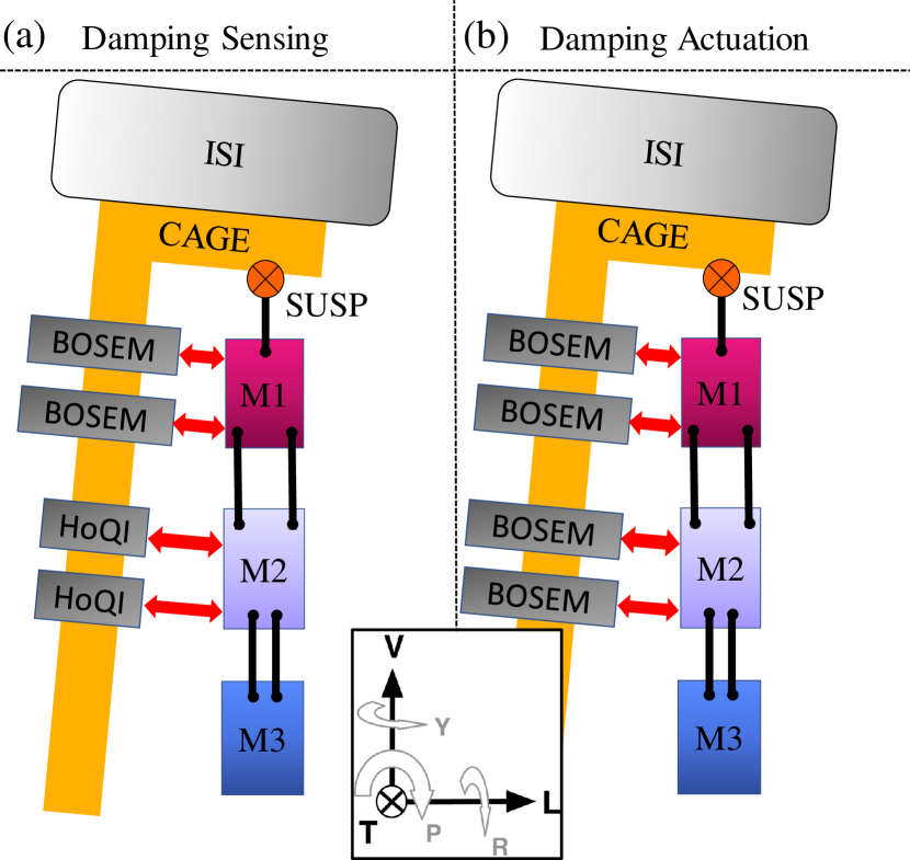
(a) Overview of the sensors used for damping, at M1, multiple BOSEM s are mounted on the cage, measuring the relative displacement between the cage and M1 in all six degrees of freedom. Similarly, at M2 four HoQI s are mounted on the cage, measuring the relative displacement between the cage and M2, but only in longitudinal (L), pitch (P), and yaw (Y).
(b) Overview of the actuators used for damping, at both M1 and M2 there are multiple BOSEM s to actuate on the suspension. By default, the BOSEM s at M1 are used for local sensing and control and provide static offsets for global control, and the BOSEM s at M2 for actuation from global interferometer signals. We investigate using the BOSEM s at M2 for actuation based on both local and global signals.
One of the LIGO A+ upgrades, planned for after the upcoming fourth observing run, is the installation of a new, larger beamsplitter APDR . This necessitates the new Big BeamSplitter Suspension (BBSS)that contains slots for optional Homodyne Quadrature Interferometer s (HoQI s)HoQI to be used as relative displacement sensors. Compact interferometric sensors intorev , like HoQI s provide significant performance improvements HoQI to the baseline Birmingham Optical Sensor and Electro-Magnetic actuator (BOSEM)Bosem ; A+Bosem . This makes the BBSS a perfect test case for modeling how better sensors could affect the performance of the suspended optics.
Figure 1 shows an overview of the BBSS, a cascade of 3 masses. The suspension system isolates the beamsplitter optic (M3) from the residual ground motion of the Internal Seismic Isolation (ISI)platform. Every step of this chain reduces the motion transmitted to the lower mass, with an power law above its pendulum frequency. The chain’s resonances must be damped to reduce the Root Mean Squared (RMS) motion of M3. The damping system works by measuring and actuating between the rigid cage and the suspended stages, depicted in Figure 2. The baseline LIGO damping design uses BOSEM s Bosem mounted on the cage to measure and actuate on the beamsplitter top mass (M1)(we call this ‘M1 BOSEM damping’).
In this paper we present a detailed investigation of the damping and noise performance if HoQI s are mounted between the beamsplitter intermediate mass (M2)and the cage, while using the BOSEM s for actuation. It is the first study showing that the improved sensitivity allows HoQI s to be used for local control at a stage closer to the optic, resulting in more control authority and improved damping without disturbing the sensitivity in the critical measurement band above 10 Hz. The combination of M2 HoQI sensing and M2 BOSEM actuation is referred to as ‘M2 HoQI damping’. We will provide a detailed noise-budget breakdown of the contributions to optic motion for the BBSS in both Length and Pitch for both the BOSEM and HoQI damping scenarios. Four targets were identified as crucial for control design: a stable controller that reduces the suspension resonance peaks, meeting 10 Hz performance requirements and reducing RMS motion.
3 Simulating the HOQI damping performance
The purpose of the damping system is to lower the quality factor of the resonances of the suspension chain at its eigenfrequencies. This reduces the total motion at M3, provides a simpler plant for implementing global interferometer controls, and reduces the RMS motion of the suspended masses and corresponding non-linear effects. Active damping is preferred over passive damping to have more freedom in shaping the frequency response of the dissipation and to allow for fine-tuning after installation. In addition to damping performance, this system should not introduce noise into the sensing region of the detector (10 Hz and above). To design the damping system we need models of the damping performance and an understanding of the noise contributions.
The following method is used to show the damping performance of M2 HoQI damping in comparison to M1 BOSEM damping. A Matlab model for simulating the damping performance of the BOSEM s at M1 exists bbssmatlab ; BBSSM . This model provides an open-loop (undamped) state-space for the suspension dynamics, and includes feedback paths and damping filters for sensing and actuating at M1. These produce the closed-loop BOSEM-damped state-space.
We expanded this implementation to include feedback paths from HoQI s sensors to BOSEM s actuators, all at M2, and designed appropriate new stable damping filters. This study is limited to the longitudinal (L) and pitch (P) degrees of freedom, which are strongly cross-coupled in the underlying mechanical equations of motion. Similar damping performance is expected for yaw (Y).
Three primary noise sources are identified: actuator noise, sensor noise, and inertial noise.
For actuator noise we re-used the validated actuator noise model of the LIGO beamsplitter suspension used in the current observing run BSFMactuator , and updated the geometry and DAC to those planned for the BBSS. For global control all actuators are used independent of the local controls, so in both the M2 HoQI and M1 BOSEM damped scenarios, actuator noise originates from both the M1 and M2 actuators. M3 actuator noise was not included since important design parameters are still missing. Actuator noise is primarily caused by the DAC voltage noise, which generates force noise at the suspended masses.
Sensor noise depends on the resolution of the individual sensors and their geometrical placement. Depending on the control filters and the loop gain, the sensor noise will be injected via actuators into the suspension. Both HoQI s and BOSEM s are relative position sensors. To measure translation and rotation, multiple sensors are used at different locations of M1 and M2. Common sensor output corresponds to translational movement, and the noise is lower than that of an individual sensor due to the multiplicity of sensors. Differential sensor outputs correspond to rotation and the noise is higher than for an individual sensor due to the short lever arm. Scripts were used to obtain the sensing noise in each degrees of freedom (dof) based on the geometric placement of BOSEM s for the M1 BOSEM damping model OSEMEUL and modified for use with the M2 HoQI damping model.
Inertial noise consists of two parts. The first part is ‘ISI noise’, the transmission of motion from the ISI (rigidly connected to SUSpension Point (SUSP)) to M3. The second part is ‘cage noise’. At high frequencies, the masses M1-M3 move much less than the cage, but the sensors can only measure the relative motions. To model this we projected the ISI movement to the M1 and M2 sensor locations. It is non-trivial to accurately determine the inertial rotation of the ISI at low frequencies, and we used recent predictions of expected tilt, synthesised from several sensors isiblend .
Since the BBSS hangs down from the ISI, the motion of the cage due to rotation of the ISI increases at each stage. However, damping performance increases substantially when measuring and actuating closer to the optic. With a total noise budget and the complete damped suspension model, the effect of M1 BOSEM versus M2 HoQI damping was compared quantitatively. The full matlab model of our simulations is shared online matlabscripts .
4 HOQI vs BOSEM damping performance
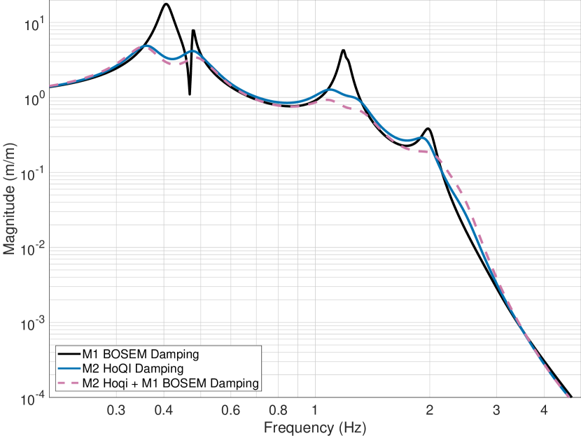
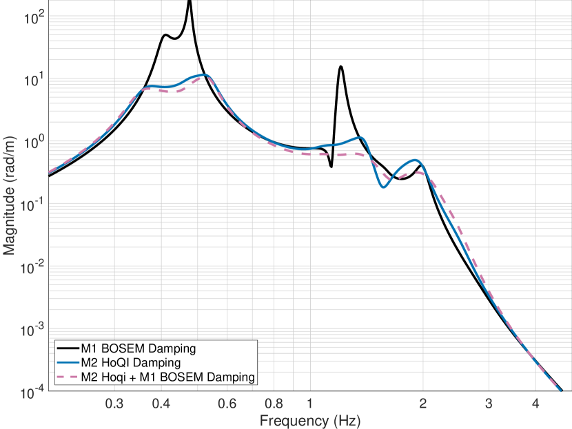
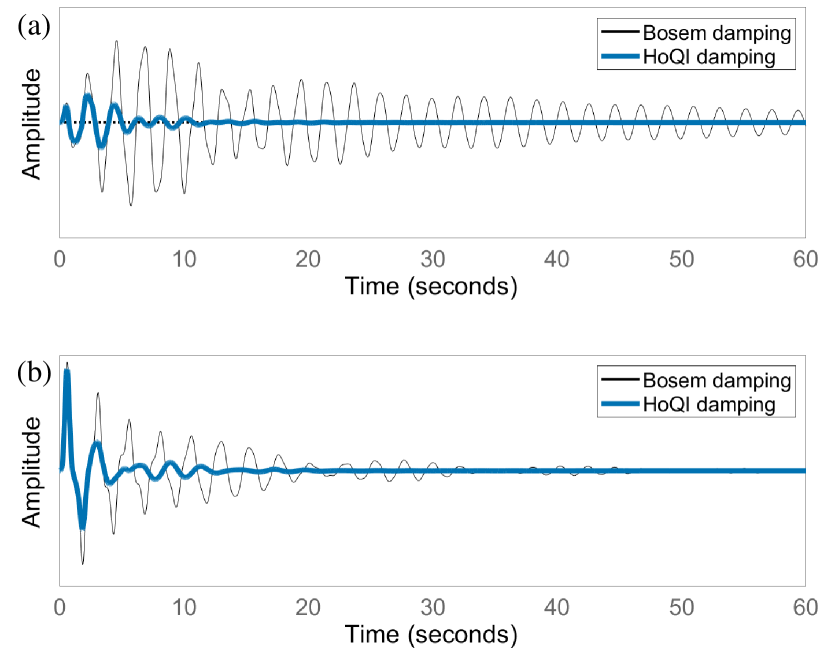
We close the control loops on the BBSS model with sensing and actuation at M2. Figure 3 shows the transfer function of ISI longitudinal motion to M3 longitudinal displacement with different damping configurations shown; the baseline sensing and damping at M1, our proposed sensing and damping at M2, and both damping methods simultaneously. It can be seen that the resonances around 0.4 Hz, 1.1 Hz and 1.8 Hz are suppressed by up to a factor of eight with M2 HoQI damping compared with (only) M1 BOSEM damping. The results for M2 HoQI damping, and M2 HoQI + M1 BOSEM damping are very similar in performance. The performance improvements in pitch (P)can be found in figure 4. The inpulse responses from the ISI to the mirror M3 in figure 7 show the improved settling time with the HoQI-damped suspension compared to BOSEM-damped. We have only considered configurations that are feasible for the BBSS.
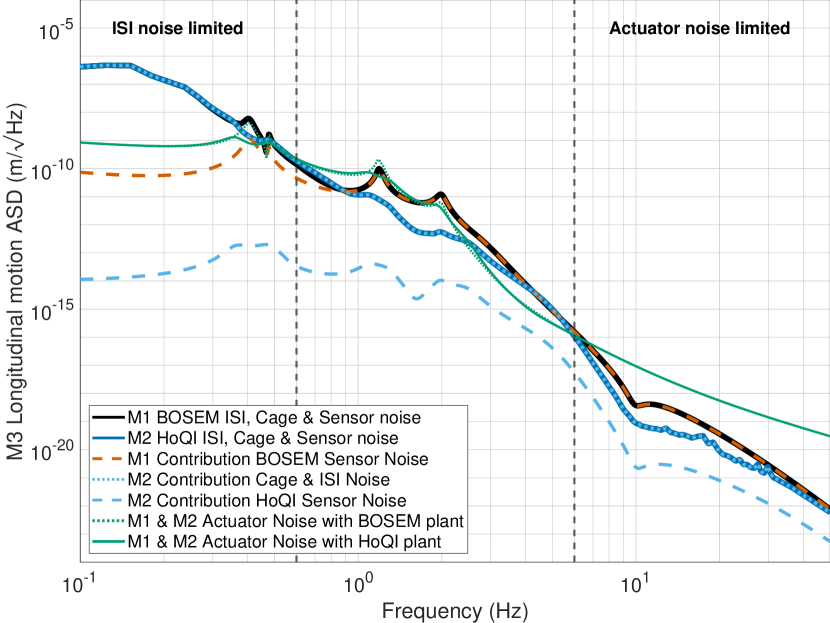
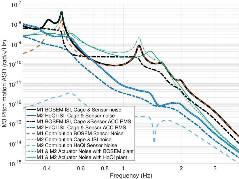
Figures 5 and 6 present the closed-loop noise budgets, showing different noise sources contributing to optic longitudinal (L)and pitch (P)movement with either M1 BOSEM or M2 HoQI damping. When excluding the actuator noise it can be seen that above 1 Hz, the HoQI-damped system always has a lower total noise than the BOSEM-damped system. Above 1 Hz the BOSEM-damped system is limited by BOSEM sensor noise, while the HoQI damped system is always limited by ISI and cage noise. Finally, the accumulated RMS movement in the pitch (P)direction at 1 Hz is a factor 60 lower for the M2 HoQI-damped system when compared to the M1 BOSEM-damped system. When taking into account actuator noise the noise budget of both methods is comparable.
The results show that using M2 HoQI-damping obtains better damping performance without introducing more noise. Figure 3 shows that when using M2 HoQI-damping, additional M1 BOSEM-damping does not bring substantial improvements. M1 BOSEM-damping has two limitations: sensor noise and dynamic coupling. For sensor noise, if the gain is increased, motion at the optic will increase rather than decrease due to the injection of BOSEM sensor noise. For dynamic coupling, only some fraction of the total kinetic energy couples to the top mass, creating an impedance-matching limit for damping. Increasing damping gain beyond this limit increases optic motion. Combining this information with the lower noise injection of the HoQI system, as shown in figures 5 and 6 provides strong motivation for deactivating BOSEM-damping in degrees of freedom where HoQI-damping can be used: longitudinal (L), pitch (P), yaw (Y).
BOSEM sensor noise and actuator noise are driving the noise budget above 1 Hz in the M1 BOSEM-damped system. Actuator noise, cage noise and inertial motion of the ISI and the cage dominates the M2 HoQI-damped budget, especially in longitudinal (L). If the sensors were instead mounted on a suspended reaction chain, present in the quadruple suspensions used for suspending the test masses of main arm-cavity optics AdvancedLigo , the cage noise will be strongly attenuated. This will result in even better performance for the HoQI damped system. Cage noise can be reduced with ‘sensor correction’, a feed-forward technique designed to subtract the inertial motion of the ISI from the HoQI sensor output. This is possible using the inertial sensors on the ISI, which measure motion in the relevant band with significant signal-to-noise ratio isiblend . This analysis has also exposed that actuation noise is a dominant noise source around 1 Hz and above 10 Hz. To realise the full improvements possible with interferometric local sensors, actuation noise should be suppressed by more than two orders of magnitude at frequencies near 1.5 Hz.
It is difficult to further reduce the noise of LIGO’s DACs and significant gains can only be made by reducing the actuation strength. In order to reduce the required actuation strength required for alignment, it is possible to offload static offsets in pitch (P)and yaw (Y)to stepper motors, as implemented successfully at Virgo payload . Additionally, slow drift in the longitudinal (L)direction can be corrected further upstream from suspension chain, at either the ISI or Hydraulic External Pre-Isolation (HEPI). If the actuators only have to compensate for drifts on short timeframes, less movement and therefore less actuation force is needed resulting in less noise from the DAC propagating to the suspensions.
5 Impact of suspension damping on gravitational-wave detection
Current simulation models don’t correctly predict the LIGO interferometers’ total noise budget for the Hz region. Steps are being taken to model non-linear couplings into DARM Lightsaber and to use machine learning for non-linear noise prediction and suppression MachineNoise ; MachinesSensitivity .
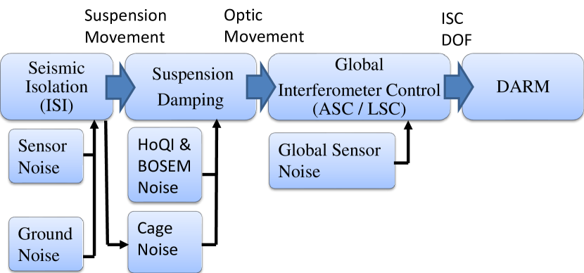
Further efforts are being made to iterate on control filter design by closing an over-arching loop, with detailed technical noise projections closedloop . Figure 8 illustrates some of the interconnections between distinct control systems. An integrated loop over the different control systems would allow for quickly evaluating the DARM performance gains seen by improving one element in the chain.
As these models are currently under development, we aren’t able to quantify the improvements of better damping (for single or multiple optics) on DARM. Instead we outline the mechanisms that link suspension dynamics and optic motion with DARM sensitivity.
Reducing the RMS motion of LIGO’s suspended optics allows for a reduction of interferometric sensing and control bandwidths, and therefore reduced control forces and lower optical sensor noise injection. Lower resonance peaks mean lower cross-coupling into different degrees of freedom. A better damped BBSS (evidenced by ‘smoother’ transfer functions), enables more robust and simpler global control options, and less of a need for frequency dependent features, which affect phase. Better damping (figure 7) and ‘smoother’ phase features should improve the quality and stability of the feed-forward, used to de-couple degrees of freedom.
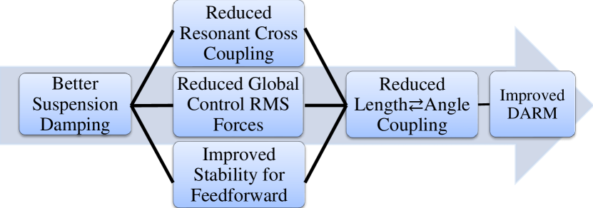
The effects of having multiple better damped and therefore easier to control core optics are outlined conceptually in figure 9. From interferometric ASC studies ASC it is known that all interferometer degrees of freedom impact DARM. Improvements in any part of this chain can lower the ‘technical noise’ contributions to DARM. Figure 9 stems from strategies which have helped resolve problems in the Hz range SAMSRCL2 , and investigations into a main offender for the Hz region SRCLMysteries .
The model adaptations we have made can be readily transferred to other triple suspensions in future upgrades. Initial studies showing the benefits for quadruple suspensions have been performed QuadDamp and we expect that similar results can be obtained for all core suspended optics. The increased sensitivity of HoQI s deeply suppresses the contribution of sensor noise and the inertial movement of the cage (cage noise) is expected to dominate the motion of the optic for BBSS triple suspension. As such, lower total noise is anticipated if HoQI s are placed on the suspended ‘reaction chain’ of the quadruple suspensions that support the test masses. Even without a precise quantification, which is necessarily dependent on the (evolving) status of the interferometer, we have linked previously successful strategies that provide causal evidence that reduced motion via better damping should result in reduced noise in DARM at frequencies between 10 and 30 Hz.
6 Conclusions
The Big BeamSplitter Suspension design has slots for installing HoQI s, providing the potential to test improved sensors (and as such better damping) for this suspension, and act as a technology demonstrator for future upgrades. We have simulated the damping performance if HoQI s are fitted and used the resulting performance as a case study for improved sensors in all suspensions. This kind of analysis is crucial for determining the improvements that can be realised in the detector, including existing limits imposed by other systems.
We have shown that by using HoQI damping at M2, instead of BOSEM damping at M1, we can reduce the resonance peaks of the plant by a factor of up to eight while simultaneously reducing the motion of the suspended optic. Reduced RMS motion means lower global control bandwidth, reduced control forces, and less non-linear, bi-linear and non-stationary couplings. A simpler plant allows for more flexible and robust global control options. This better plant stability permits improvements to the feed-forward control. These aspects will improve the sensitivity of the LIGO interferometers in the control-noise-limited Hz region.
Acknowledgements.
We thank Norna Robertson and the Advanced LIGO Suspensions team for work developing the BBSS dynamics model. The authors gratefully acknowledge the support of the United States National Science Foundation (NSF) for the construction and operation of the LIGO Laboratory and Advanced LIGO. LIGO was constructed by the California Institute of Technology and Massachusetts Institute of Technology with funding from the United States NSF, and operates under cooperative agreement PHY-1764464, Advanced LIGO was built under award PHY-0823459. The authors acknowledge the support of the Institute for Gravitational Wave Astronomy at the University of Birmingham, STFC grants ‘Astrophysics at the University of Birmingham’ grant ST/S000305/1 and ‘The A+ upgrade: Expanding the Advanced LIGO Horizon‘ ST/S00243X/1. The support for Cardiff University grants; Leverhulme Trust: PLP-2018-066 and UKRI — Science and Technology Facilities Council (STFC): ST/V005618/1. This project has received funding from the European Research Council (ERC) under the European Union’s Horizon 2020 research and innovation programme (grant agreement No. 865816).Data Availability Statement
The data that support the findings of this study are available from the corresponding author upon reasonable request. The scripts used to simulate the BBSS suspension and for generating all figures in this paper are available online matlabscripts .
References
References
- (1) The LIGO Scientific Collaboration, The Virgo Collaboration, Abbott, B. P., R. Abbott, T. D. Abbott, M. R. Abernathy, F. Acernese, K. Ackley, C. Adams, T. Adams, P. Addesso, R. X. Adhikari et al. Observation of gravitational waves from a binary black hole merger. Phys. Rev. Lett., 116:061102, Feb 2016.
- (2) The LIGO Scientific Collaboration, The Virgo Collaboration, Abbott, R., T. D. Abbott, F. Acernese, K. Ackley, C. Adams, N. Adhikari, R. X. Adhikari, V. B. Adya, C. Affeldt et al. Gwtc-2.1: Deep extended catalog of compact binary coalescences observed by ligo and virgo during the first half of the third observing run, 2021.
- (3) The LIGO Scientific Collaboration, The Virgo Collaboration, The KAGRA Collaboration, Abbott, R., T. D. Abbott, F. Acernese, K. Ackley, C. Adams, N. Adhikari, R. X. Adhikari, V. B. Adya, C. Affeldt, D. Agarwal et al. Gwtc-3: Compact binary coalescences observed by ligo and virgo during the second part of the third observing run, 2021.
- (4) The LIGO Scientific Collaboration, J Aasi, B P Abbott, R Abbott, T Abbott, M R Abernathy, K Ackley, C Adams, T Adams, P Addesso, R X Adhikari et al. Advanced LIGO. Classical and Quantum Gravity, 32(7):074001, mar 2015.
- (5) The Virgo Collaboration, F Acernese, M Agathos, K Agatsuma, D Aisa, N Allemandou, A Allocca, J Amarni, P Astone, G Balestri et al. Advanced virgo: a second-generation interferometric gravitational wave detector. Classical and Quantum Gravity, 32(2):024001, dec 2014.
- (6) The LIGO Scientific Collaboration, The Virgo Collaboration, Abbott, B. P., R. Abbott, T. D. Abbott, F. Acernese, K. Ackley, C. Adams, T. Adams, P. Addesso, R. X. Adhikari, V. B. Adya et al. Gw170817: Observation of gravitational waves from a binary neutron star inspiral. Phys. Rev. Lett., 119:161101, Oct 2017.
- (7) B. P. Abbott, R. Abbott, T. D. Abbott, F. Acernese, K. Ackley, C. Adams, T. Adams, P. Addesso, R. X. Adhikari, V. B. Adya et al. Multi-messenger observations of a binary neutron star merger. The Astrophysical Journal, 848(2):L12, oct 2017.
- (8) J. Miller, L. Barsotti, S. Vitale, P. Fritschel, M. Evans, and D. Sigg. Prospects for doubling the range of advanced ligo. Phys. Rev. D, 91:062005, Mar 2015.
- (9) H. Yu, D. Martynov, S. Vitale, M. Evans, D. Shoemaker, B. Barr, G. Hammond, S. Hild, J. Hough, S. Huttner et al. Prospects for detecting gravitational waves at 5 hz with ground-based detectors. Phys. Rev. Lett., 120:141102, Apr 2018.
- (10) S M Aston, M A Barton, A S Bell, N Beveridge, B Bland, A J Brummitt, G Cagnoli, C A Cantley, L Carbone, A V Cumming et al. Update on quadruple suspension design for advanced LIGO. Classical and Quantum Gravity, 29(23):235004, oct 2012.
- (11) F. Matichard, B. Lantz, K. Mason, R. Mittleman, B. Abbott, S. Abbott, E. Allwine, S. Barnum, J. Birch, S. Biscans et al. Advanced ligo two-stage twelve-axis vibration isolation and positioning platform. part 1: Design and production overview. Precision Engineering, 40:273–286, 2015.
- (12) F. Matichard, B. Lantz, K. Mason, R. Mittleman, B. Abbott, S. Abbott, E. Allwine, S. Barnum, J. Birch, S. Biscans et al. Advanced ligo two-stage twelve-axis vibration isolation and positioning platform. part 2: Experimental investigation and tests results. Precision Engineering, 40:287–297, 2015.
- (13) A. Buikema, C. Cahillane, G. L. Mansell, C. D. Blair, R. Abbott, C. Adams, R. X. Adhikari, A. Ananyeva et al. Sensitivity and performance of the advanced ligo detectors in the third observing run. Phys. Rev. D, 102:062003, Sep 2020.
- (14) G. Vajente, Y. Huang, M. Isi, J. C. Driggers, J. S. Kissel, M. J. Szczepańczyk, and S. Vitale. Machine-learning nonstationary noise out of gravitational-wave detectors. Phys. Rev. D, 101:042003, Feb 2020.
- (15) J.Conklin, D. Jariwala, T. Pechsiri, H. Inchauspe, P. Fulda, and D. Tanner. Progress in developing a differential osem (dosem). techreport G1900464, University of Florida, https://dcc.ligo.org/LIGO-G1900464, March 2022. manuscript in preperation.
- (16) C. Collette, F. Nassif, J. Amar, C. Depouhon, and S.-P. Gorza. Prototype of interferometric absolute motion sensor. Sensors and Actuators A: Physical, 224:72–77, 2015.
- (17) J. Watchi, S. Cooper, B. Ding, C. M. Mow-Lowry, and C.Collette. Contributed review: A review of compact interferometers. Review of Scientific Instruments, 89(12):121501, 2018.
- (18) J. Smetana, R. Walters, S. Bauchinger, A. Singh Ubhi, S. Cooper, D. Hoyland, R. Abbott, C. Baune, P. Fritchel, O. Gerberding et al. Compact michelson interferometers with subpicometer sensitivity, 2022.
- (19) O. Gerberding. Deep frequency modulation interferometry. Opt. Express, 23(11):14753–14762, Jun 2015.
- (20) J. Miller, S. Ngo, A. J. Mullavey, B.J. J. Slagmolen, D. A. Shaddock, and David E. McClelland. Control and tuning of a suspended fabry perot cavity using digitally enhanced heterodyne interferometry. Opt. Lett., 37(23):4952–4954, Dec 2012.
- (21) T. T. L. Tsang, T. G. F. Li, T. Dehaeze, and C. Collette. Optimal sensor fusion method for active vibration isolation systems in ground-based gravitational-wave detectors, 2021.
- (22) F. Badaracco, J. V. van Heijningen, E. Ferreira, and A. Perali. A cryogenic and superconducting inertial sensor for the lunar gravitational–wave antenna, the einstein telescope and selene-physics, 2022.
- (23) M. Zumberge, J. Berger, J. Otero, and E. Wielandt. An Optical Seismometer without Force Feedback. Bulletin of the Seismological Society of America, 100(2):598–605, 04 2010.
- (24) G. Zhao, B. Ding, J. Watchi, A. Deraemaeker, and C. Collette. Experimental study on active seismic isolation using interferometric inertial sensors. Mechanical Systems and Signal Processing, 145:106959, 2020.
- (25) J. V. van Heijningen, A. Bertolini, and J. F. J. van den Brand. A novel interferometrically read out inertial sensor for future gravitational wave detectors. In 2018 IEEE Sensors Applications Symposium (SAS), pp. 1–5, 2018.
- (26) F. Guzmán Cervantes, L. Kumanchik, J. Pratt, and J. M. Taylor. High sensitivity optomechanical reference accelerometer over 10 khz. Applied Physics Letters, 104(22):221111, 2014.
- (27) S. M. Köhlenbeck. Towards the SQL Interferometer Length Stabilization at the AEI 10 m-Prototype. PhD thesis, Leibniz U., Hannover, 2018.
- (28) S J Cooper, C J Collins, L Prokhorov, J Warner, D Hoyland, and C M Mow-Lowry. Interferometric sensing of a commercial geophone. Classical and Quantum Gravity, 39(7):075023, mar 2022.
- (29) C. M. Mow-Lowry and D. Martynov. A 6d interferometric inertial isolation system. Classical and Quantum Gravity, 36(24):245006, nov 2019.
- (30) S.L. Kranzhoff, J. Lehmann, R. Kirchhoff, M. Carlassara, S.J. Cooper, P. Koch, S. Leavey, C.M. Mow-Lowry, J. Wöhler, J. von Wrangel et al. A vertical inertial sensor with interferometric readout. manuscript in preperation, 2022.
- (31) J. J. McCann, J. Winterflood, L. Ju, and C. Zhao. A multi-orientation low-frequency rotational accelerometer. Review of Scientific Instruments, 92(6):064503, 2021.
- (32) J. D. Otero. Development and characterization of an observatory-class, broadband, non-fedback, leaf-spring interferometric seismometer. PhD thesis, University of California, 2009.
- (33) B. Ding, G. Zhao, J. Watchi, and C. Collette. Development of a high resolution optical inertial sensor and the huddle test of the sensors, 2018.
- (34) T. Chang, Z. Wang, Y. Yang, Y. Zhang, Z. Zheng, L. Cheng, and H. Cui. Fiber optic interferometric seismometer with phase feedback control. Opt. Express, 28(5):6102–6122, Mar 2020.
- (35) M. Ross. Precision Mechanical Rotation Sensors for Terrestrial Gravitational Wave Observatories. phdthesis, University of Washington, August 2020.
- (36) C. Collette, S. Janssens, P. Fernandez-Carmona, K. Artoos, M. Guinchard, C. Hauviller, and A. Preumont. Review: Inertial sensors for low-frequency seismic vibration measurement. Bulletin of the Seismological Society of America, 102:1289–1300, 08 2012.
- (37) K. Venkateswara, C.A. Hagedorn, M.D. Turner, T. Arp, and J.H. Gundlach. A high-precision mechanical absolute-rotation sensor. Review of Scientific Instruments, 85(1):015005, 2014.
- (38) B. Ding, G. Zhao, J. Watchi, A. Sider, and C. Collette. An interferometric inertial sensor for low-frequency seismic isolation. Sensors and Actuators A: Physical, 335:113398, 2022.
- (39) J. J. McCann, J. Winterflood, L. Ju, and C. Zhao. A multi-orientation low-frequency rotational accelerometer. Review of Scientific Instruments, 92(6):064503, 2021.
- (40) A Singh Ubhi, J. Smetana, T. Zhang, S. Cooper, L. Prokhorov, J. Bryant, D. Hoyland, H. Miao, and D. Martynov. A six degree-of-freedom fused silica seismometer: design and tests of a metal prototype. Classical and Quantum Gravity, 39(1):015006, dec 2021.
- (41) W. Z. Korth, A. Heptonstall, E. D. Hall, K. Arai, E. K. Gustafson, and R. X. Adhikari. Passive, free-space heterodyne laser gyroscope. Classical and Quantum Gravity, 33(3):035004, jan 2016.
- (42) A. Huddart. Bigger beamsplitter suspension (BBSS) preliminary design document. Technical report, Science and Technology Facilities Council, Rutherford Appleton Laboratory, T1900581, September 2019.
- (43) J. S. Kissel. On seismic isolation in 2nd generation detectors. techreport, Massachusetts Institute of Technology, https://dcc.ligo.org/LIGO-G1200556-v1, May 2012.
- (44) S J Cooper, C J Collins, A C Green, D Hoyland, C C Speake, A Freise, and C M Mow-Lowry. A compact, large-range interferometer for precision measurement and inertial sensing. Classical and Quantum Gravity, 35(9):095007, mar 2018.
- (45) L Carbone, S M Aston, R M Cutler, A Freise, J Greenhalgh, J Heefner, D Hoyland, N A Lockerbie, D Lodhia, N A Robertson et al. Sensors and actuators for the advanced LIGO mirror suspensions. Classical and Quantum Gravity, 29(11):115005, may 2012.
- (46) S. J. Cooper, C. M. Mow-Lowry, D. Hoyland, J. Bryant, A. Ubhi, J. O’Dell, A. Huddart, S. Aston, and A. Vecchio. Sensors and actuators for the advanced ligo a+ upgrade. Review of Scientific Instruments, 94(1):014502, 2023.
- (47) Norna Robertson and Mark Barton. Conceptual design of a larger beamsplitter suspension. techreport LIGO-T1400296, LIGO, https://dcc.ligo.org/LIGO-T1400296, April 2014.
- (48) K. Strain, N. Robertson, A. Effler, A. Huddart, and S. Aston. Record of changes to triple suspension MATLAB model to BBSS. software T2000599, LIGO, https://dcc.ligo.org/LIGO-T2000599, October 2020.
- (49) J. Kissel and N. A. Robertson. Beam splitter / folding mirror suspension(bsfm) actuation ranges. techreport, California Institute of Technology and Massachusetts Institute of Technology, https://dcc.ligo.org/LIGO-T1100602/public, January 2013.
- (50) B. Lantz and S. Aston. HSTS OSEM noise estimates. software G2002065-v1, LIGO, https://dcc.ligo.org/LIGO-G2002065-v1, March 2013.
- (51) B. Lantz. Design for new rx/ry blend filters for stage 2 of the BSC-ISI. techreport LIGO-T2100273, Stanford University, https://dcc.ligo.org/T2100273, June 2021.
- (52) L. Naticchioni on behalf of the Virgo Collaboration The payloads of Advanced Virgo: current status and upgrades Journal of Physics: Conference Series, 957(1):012002, February 2018.
- (53) J. van Dongen, L. Prokhorov, S. J Cooper, J. Kissel, J. C Driggers, A. Effler, M. Kasprzack, B. Lantz, A. Pele, and C. M. Mow-Lowry. Matlab scripts for simulating Big Beamsplitter Suspensio damping performance and reproducing paper plots. software, Nikhef, https://gitlab.nikhef.nl/jvdongen/hoqi-damping-paper-matlab-scripts, January 2023.
- (54) T. Andric and J. Harms. Lightsaber: A simulator of the angular sensing and control system in ligo. Galaxies, 9(3), 2021.
- (55) G. Vajente. Data mining and machine learning improve gravitational-wave detector sensitivity. Phys. Rev. D, 105:102005, May 2022.
- (56) L. McCuller. Closing the loop on SEI and ISC for interferometer analysis. techreport G2101099-v1, Massachusetts Institute of Technology, https://dcc.ligo.org/LIGO-G2101099, May 2021.
- (57) G. Mueller, R. Abbott, L. Barsotti, M. Evans, S. Ballmer, V. Frolov, P. Fritschel, and R. Adhikari. Advanced LIGO length sensing and control final design. techreport T1000298-T, California Institute of Technology, Massechusetts Institute of Technology, LIGO Hanford Observatory, LIGO Livingston Observatory, https://dcc.ligo.org/LIGO-T1000298/public, June 2010.
- (58) S. Cooper, B. Lantz, J. Warner, C. Di Fronzo, and C. Mow-Lowry. Some thoughts on controlling SRCL. techreport T1900107, School of Physics and Astronomy, University of Birmingham, https://dcc.ligo.org/LIGO-T1900107, March 2019.
- (59) B. Lantz. Measurment and mysteries of SRCL noise. techreport G200193-V1, LIGO Control Systems Working Group, https://dcc.ligo.org/LIGO-G2100193, February 2021.
- (60) B. Lantz, E. Bonilla, and C. Mow-Lowry. Thoughts on damping the testmass from the UIM. techreport LIGO-T1800504, https://dcc.ligo.org/LIGO-T1800504, November 2018.
Acronyms
- ASC
- Alignment Sensing and Control
- BBSS
- Big BeamSplitter Suspension
- BOSEM
- Birmingham Optical Sensor and Electro-Magnetic actuator
- DARM
- Differential ARM length
- dof
- degrees of freedom
- HEPI
- Hydraulic External Pre-Isolation
- HoQI
- Homodyne Quadrature Interferometer
- ISI
- Internal Seismic Isolation
- L
- longitudinal
- LIGO
- Laser Interferometer Gravitational-Wave Observatory
- LSC
- Length Sensing and Control
- M1
- beamsplitter top mass
- M2
- beamsplitter intermediate mass
- M3
- beamsplitter optic
- P
- pitch
- RMS
- Root Mean Squared
- SUSP
- SUSpension Point
- Y
- yaw