An Arduino based heartbeat detection device (ArdMob-ECG) for real-time ECG analysis
Abstract
This technical paper provides a tutorial to build a low-cost (10-100 USD) and easy to assemble ECG device (ArdMob-ECG) that can be easily used for a variety of different scientific studies. The advantage of this device is that it automatically stores the data and has a built-in detection algorithm for heartbeats. Compared to a clinical ECG, this device entails a serial interface that can send triggers via USB directly to a computer and software (e.g. Unity, Matlab) with minimal delay due to its architecture. Its software and hardware is open-source and publicly available. The performance of the device regarding sensitivity and specificity is comparable to a professional clinical ECG and is assessed in this paper. Due to the open-source software, a variety of different research questions and individual alterations can be adapted using this ECG. The code as well as the circuit is publicly available and accessible for everyone to promote a better health system in remote areas, Open Science, and to boost scientific progress and the development of new paradigms that ultimately foster innovation.
Keywords: ArdMob-ECG, AD8232, Heart rate monitor, Arduino, ECG, heartbeat detection, QRS detection, R-peak detection, Pan-Tompkins algorithm
1 Introduction
In the recent past, neuroscience research has identified interoception as an important factor contributing to metacognition, empathy, and the experience of the self (Fukushima \BOthers., \APACyear2011; Meessen \BOthers., \APACyear2016). Interoceptive signals such as the heart rate, measured with an ECG has thereby been of special interest. These interoceptive signals can be used for a variety of different applications like research studies, modern therapies, but also video games. For example, different projects develop the integration of the heart rate as feedback into virtual environments to develop more immersive experiences for biofeedback in the treatment of ADHD, for the use of more immersive meditation applications, or even to automatically adapt the difficulty and scariness of video games.
However, clinical ECG machines are usually heavy, expensive, and require being operated by trained technical and medical personnel. Utilizing an easy to use, inexpensive, lightweight, and reliable technical device for measuring heart rate and its components would advance the progress in scientific research. In addition, in light of the global Covid-19 pandemic, an easy to use device would also allow the recording of data at the home of the participants with simple instructions and without any additional risk of the physical presence of the scientists during the pandemic.
This paper describes an Arduino-based heartbeat detection device (ArdMob-ECG) that integrates the AD8232 module for real-time ECG analysis. The ArdMob-ECG is easy to assemble, light-weight, small and transportable, inexpensive, yet reliable, and can be used without clinical personnel with simple instructions. This paper is meant as a guide for scientists to independently assemble the device for their own scientific studies.
2 Electrocardiogram (ECG)
2.1 ECG characteristics
An Electrocardiogramm (ECG) is a widely-used painless and non-invasive technique that is most commonly used to determine heart rate, rhythm, or frequency. The QRS complex, which represents the ventricular depolarization of the heart, is in focus when analyzing heartbeat data. The QRS complex describes the phases around a heartbeat and consists of three waves — Q, R, and S, and usually lasts between 0.06–0.10 seconds (Kashani \BBA Barold, \APACyear2005). The Q-wave starts through the depolarization of the interventricular septum. The highest potential is found in the subsequent R-peak which reflects the depolarization of the myocardium of both heart chambers. The R-wave/peak is usually used for calculating the heart rate variability (HRV). The R-peak is followed by a downward deflection which can be referred to as the S-wave. The time between two R-peaks is the interbeat interval (IBI) (Christensen \BBA Wright, \APACyear2014).
2.2 Use of medical ECG machines in scientific research
An ECG can monitor the heart activity of an individual and detect e.g. arrhythmias that can indicate heart problems. This has an immense meaning for monitoring the participants cardiac health. Usually a clinical ECG machine which sometimes costs several thousand US-Dollar is needed and due to the cost and the weight of the ECG machine, usually hospitalization is needed for an ECG-assessment. Furthermore, clinical ECG machines usually do not allow changes in their built-in software nor a direct serial interface to other programs. Therefore, an inexpensive device ( 50 $) that is easy to use, easy to self-assemble, and easy to transport can provide a solution for more remote areas that do not have a health system in range.
3 An Arduino-based ECG device using the AD8232 module
An Arduino is a programmable single-board microcontroller that comes with its own software integrated development environment (IDE). The software is programmed in an abstraction of C++ and can be loaded via a USB cable to the Arduino board. The board can be equipped with different sensors and modules.
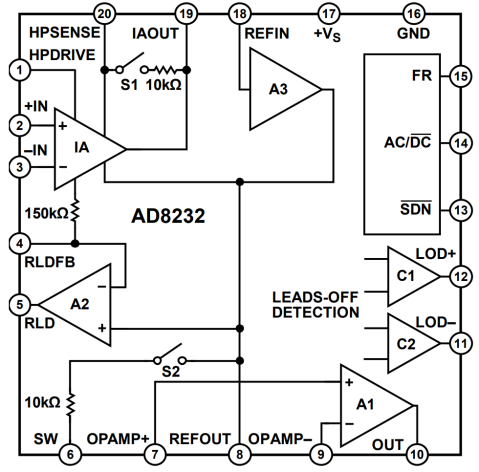
The ArdMob-ECG described in this paper utilizes the AD8232 module, a small chip measuring the electrical signal of the heart that is then translated to an ECG waveform. The AD8232 integrates signals for ECG and other biopotential measurements and is specialized to extract, amplify, and filter small biosignals even in the presence of noisy conditions such as remote electrode placement and movement. The AD8232 consists of specialized instrumentation, operational, and a drive amplifier. Additionally, the chip provides a mid supply reference buffer and a built-in high and low pass filter (Kanani \BBA Padole, \APACyear2018). A schematic functional block diagram of the chip can be seen in Figure 1.
The ArdMob-ECG described here is a reliable yet inexpensive, between 10 and 150 Euro, and easy to use ECG device for scientific studies. Due to its light weight and plug and play mechanism, it can also be operated by non-clinical personnel outside of the laboratory. It can also be battery operated without the need of any energy outlets. The device integrates the AD8232 Single Lead Heart Rate monitor module soldered on a standard Arduino board to reliably record data, calculate the heart beat, and save it on an on board micro-SD card.
The ArdMob-ECG implements a simplification of the Pan-Tompkins algorithm to calculate the occurrence of heartbeats in near real time. Different data (e.g. timestamps, raw data) can be saved on a built-in micro SD card, while other data such as triggers can be sent directly to another device using a serial interface (USB-connection). Thus, triggers can be sent with minimal delay. The heartbeat analysis can already be calculated locally on the Arduino.
The Arduino can also provide auditory feedback whenever a heartbeat is detected. This tone can also be easily adjusted to occur faster, slower or with a specific delay to the actual heartbeat, depending on the scientific paradigm (e.g. the widely used interoceptive sensitivity paradigm (Garfinkel \BOthers., \APACyear2015)).
With respect to scientific purposes, this device can provide solutions for scientific studies since it is fast to compute and introducing a low latency due to a direct objective machine layer (C++) that allows for faster processing, while having a very low power consumption of around 25mA. Furthermore, the variables can be easily modified and additional triggers can be implemented, for example, directly playing the sounds faster or slower according to the last R-R interval (Suzuki \BOthers., \APACyear2013; Brener \BOthers., \APACyear1993; Wiens \BBA Palmer, \APACyear2001).
The AD8232 module in combination with an Arduino has been used in prior studies for heartbeat detection (e.g. Kanani \BBA Padole, \APACyear2018; Bravo-Zanoguera \BOthers., \APACyear2019; Simanjuntak \BOthers., \APACyear2020; Bhosale \BBA Bhosale, \APACyear2016). However, in order to make it easier for researchers to reconstruct the ArdMob-ECG for use in further studies, the current paper will also provide the code and a clear schematic of the hardware. The following sections provide a comprehensive and detailed description of the device’s hardware and software with the aim of enabling researchers to independently assemble the device for use in scientific studies.
3.1 Design of the Hardware
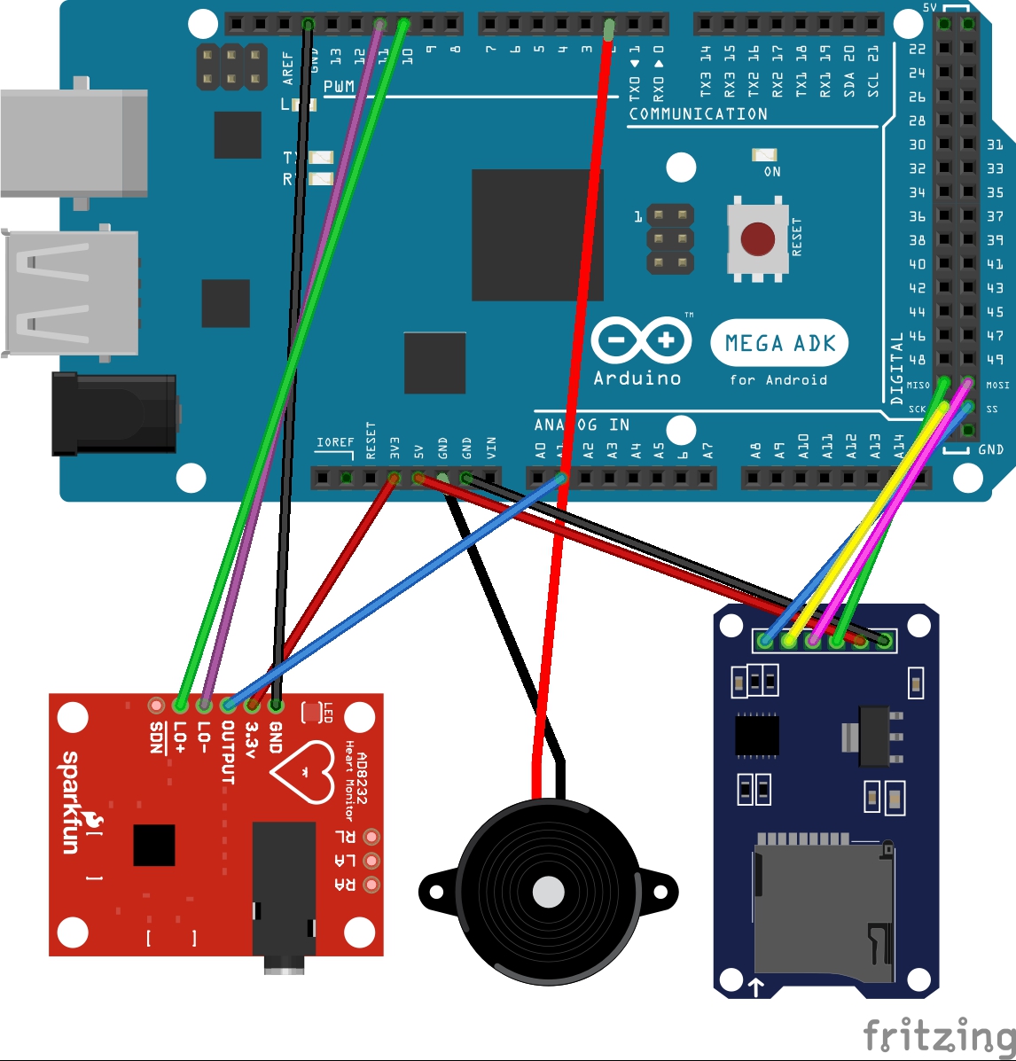
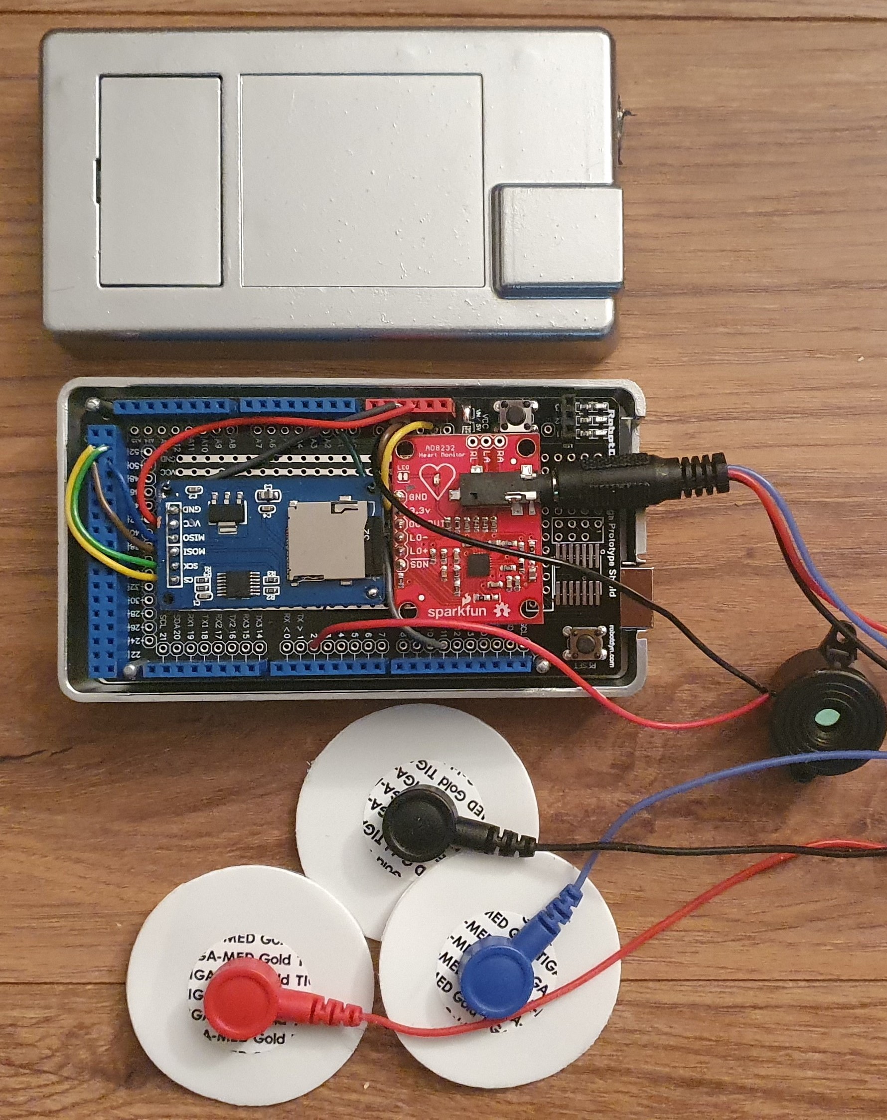
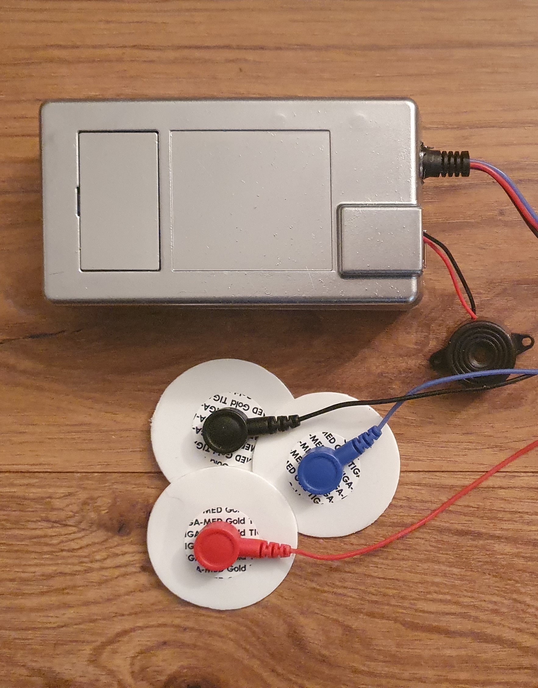
The Arduino is capable of a modular build as it can be equipped relatively easy with different sensors, chips, and modules. The AD8232 ECG sensor (\APACcitebtitleAnalog Devices AD8232 Overview, \APACyear\bibnodate) is a module that can be soldered onto an Arduino. It entails a connection cable that is plugged into the 2.54 pin (headphone) jack of the AD8232 module. The connection cable has place for 3 electrodes and can be used with any standard clinical ECG electrodes. The electrodes are be attached onto the participant according to the classic lead II configuration which is standard in many scientific studies (Christensen \BBA Wright, \APACyear2014; Clifford \BOthers., \APACyear2006). However, other electrode setups are possible. An Arduino Mega 2560 R3 with an ATmega2560 processor, equipped with a generic prototype shield was used. An AD8232 heart-rate module, an electrical piezo sound buzzer (UKCOCO DC 3 – 24 V 85 dB Piezo buzzer), and a micro SD memory card SPI reader (AZDelivery, Deggendorf, Bavaria, Germany) to allow serial communication and on time analysis of the signal were soldered on a standard prototype shield (RobotDyn, Zhuhai, China) that is attached to the Arduino. Figure 2 provides a detailed schematic diagram of the circuit. Additionally, the ECG-device is embedded in a plastic case that is shielded in aluminium to reduce electrical interference from the surrounding. Figure 3 depicts the setup without the aluminium shielding after soldering the AD232 sensor, and Figure 3 shows the device inside the aluminium case after soldering the Piezo buzzer and with the electrodes cable attached to the headphone jack of the AD8232 sensor. Additional information about practical assembly of the device is presented in subsection 3.3.
3.2 Design of the Software
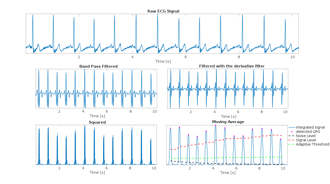
In order to analyze an ECG, a peak detection algorithm is usually used. One such algorithm is the Pan-Tompkins algorithm, which is commonly used for detecting the QRS complex in ECG, utilizing a series of low and high pass filters to detect the frequencies in the signal and to remove background noise (Pan \BBA Tompkins, \APACyear1985). Specifically, the Pan-Tompkins algorithm applies an adaptive low pass filter, followed by an adaptive high pass filter in order to reduce background noise. In a next step, this signal is used for an adaptive threshold peak detection (see also Figure 4).
Based on the Pan-Tompkins algorithm, the software for the ArdMob-ECG described in this paper was adapted from Milner (\APACyear2015) which poses a simplification of the algorithm used in Chen \BBA Chen (\APACyear2003). The software provides an on board real-time analysis of the heartbeat, implementing the adaptive high pass and low pass filtering, and adaptive thresholding of the Pan-Tompkins algorithm. In contrast to the Pan-Tompkins algorithm, no derivative filter and no squaring were implemented. Prerecorded ECG-signals taken from Milner (\APACyear2015) were used to train the adaptive filtering and thresholding models prior to data collection in order to improve the detection accuracy. When noise and muscle artifacts are present that interfere with QRS detection, the algorithm switches back to reliable QRS detection within seconds as soon as the artifacts are absent. In the software, the buffer for the high pass (M) and low pass filter (N) as well as the window size for the QRS-algorithm (winSize) can be tweaked to adjust for the quality of the incoming data.
The ArdMob-ECG detects and computes the QRS-complex and without the need for further computations, saves it on the microSD card. However, it can also send it directly to a computer or tablet as a trigger. For example, in the VR implementation described in section 4, whenever a heartbeat is detected, a trigger is sent to a PC to activate the Unity code, and the other data is saved on the microSD card. In addition, the code saves the date and timestamp of each data point, and a timer was implemented that counts the elapsed time, as well as a counter for the number of recorded data-points, if enabled. The data is automatically saved on the microSD card and shows an error when no data can be written on the SD card.
With regards to the sound feedback from the Piezo buzzer, it can be decided if tones should be played concurrently with the QRS detection i.e. in the same rhythm, or faster or slower (a percentage can be tuned) with respect to the last QRS-QRS interval.
The software can be found in the code section (Appendix A. of this manuscript) as well as in the GitHub repository (Möller, \APACyear2021).
3.3 Tips and tricks
When first setting up the system, it is recommended to test the equipment for malfunctions first before soldering them together. For the first prototype, it is easiest to connect the modules via jumper cables to the respective pins depicted in Figure 2. The heartbeat detection should already work using the jumper cables even though a lot of noise is introduced. Another testing step before soldering the modules to the Arduino board is to solder them to a prototype shield where all relevant pins are accessible. This will further improve the quality of the data and reduce noise. In this step, make sure that nothing is blocking the slot of the microSD card module.
Since the micro SD card saves data according to the FAT file system using the 8.3 format, the filename that one chooses for the data must not exceed 8 characters (e.g. the number or the initials of your participant). If there is a file with the same name and format, new data will be appended to the previous datafile. The data can be stored as a .csv or .txt file. To change the format, simply change the extension of the output string accordingly.
For further information and help with assembly please do not hesitate to contact me via email.
4 Implementation
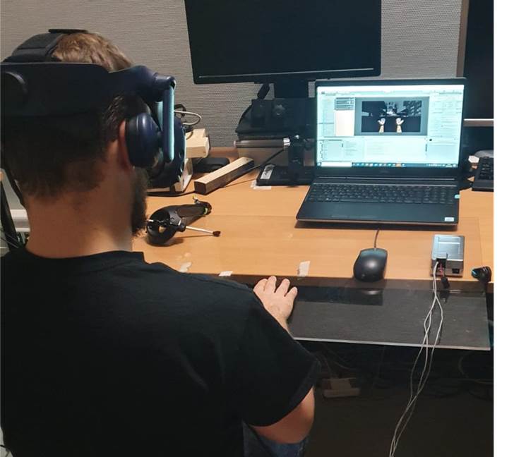
The ArdMob-ECG is currently being used in several ongoing studies. In one study, it is used in the interoceptive sensitivity paradigm where participants have to evaluate if they hear their own heartbeat, or if the sound is played faster or slower than their own heartbeat. In a next step, the device detects heartbeats and whenever a heartbeat is detected, a trigger is sent to a PC through a Unity interface to activate a Unity script. In this experiment, depending on the conditions, this leads to the red flashing of a virtual hand in a virtual reality cardiac rubber hand illusion paradigm similar to that described in Suzuki \BOthers. (\APACyear2013). The Unity code for this implementation can be found in Appendix B and in the GitHub repository (Möller, \APACyear2021).

5 Validation
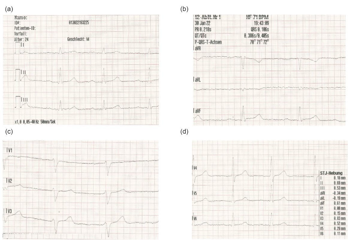
To assess the quality of data obtained from the three channel ArdMob-ECG, data from 12 channel ECG from a clinical ECG machine (ZOLL X Series CCT Defibrillator) of a German ambulance and was recorded simultaneously for three seconds on one healthy 24 year old participant. The ZOLL X Series CCT Defibrillator ECG-device is standard equipment and is routinely used in german ambulance vehicles.
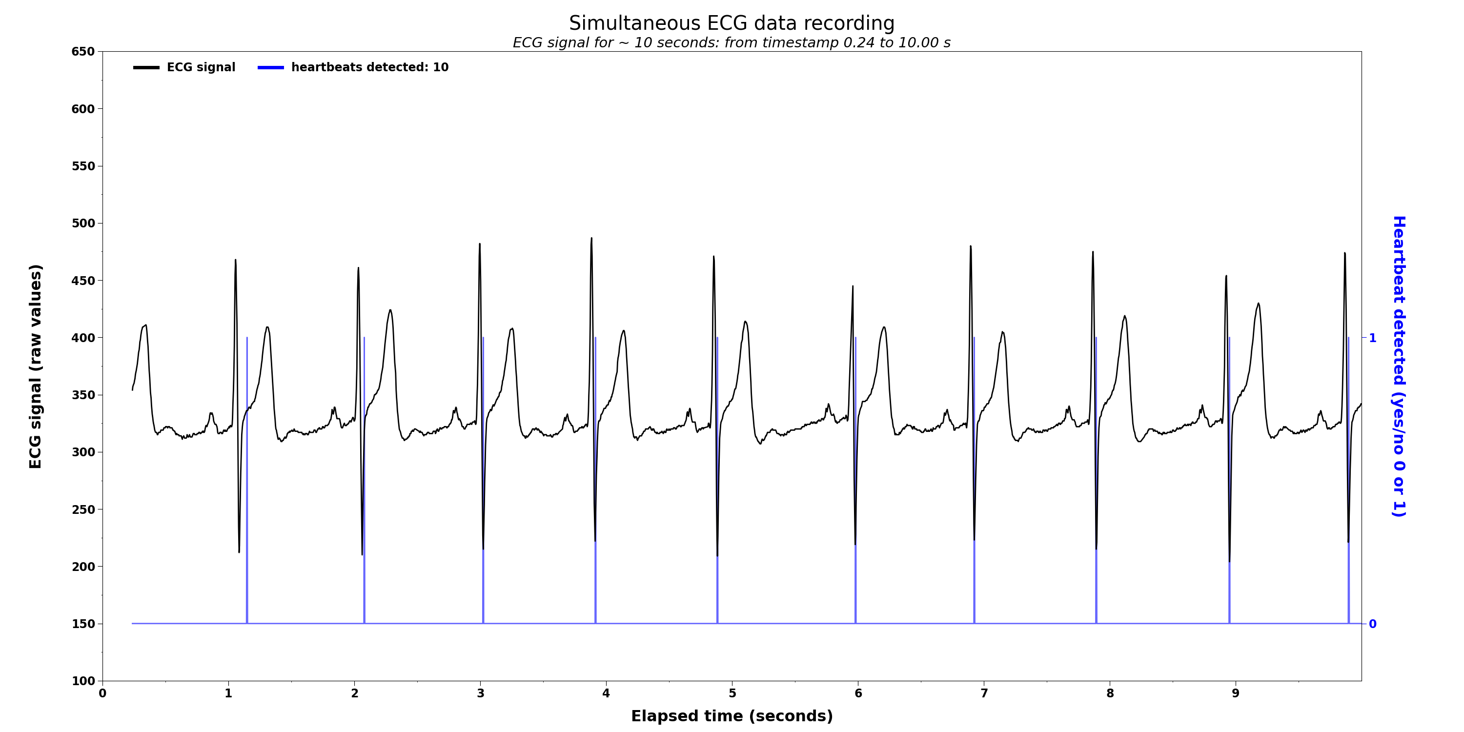
Figure 6 shows the data from the Arduino based ECG device, and Figure 7 shows a scan of the data obtained by the clinical ECG machine. By visually comparing both Figures, the data quality of the Arduino based ECG seems comparable to the clinical ECG. Furthermore, a trained medical expert compared both data outputs and assessed the validity of the heartbeat detection. Both devices managed to detect the heartbeats.
In addition, a five minutes and three second long ECG using the ArdMob-ECG was recorded. A trained paramedic then examined the recorded ECG signal and counted the heartbeats visually. The software and the paramedic both detected 347 heartbeats within this five minutes and three seconds timeframe. The paramedic also assessed that the ECG detection of the software was always identifying the R-peak correctly. Therefore, the sensitivity and specificity of the Arduino based ECG was 100%. Besides the R-peak, the paramedic also clearly detected the P,Q,R,S, and T components of the ECG data gathered by the Arduino. Figure 8 shows the P,Q,R,S,T components of a heartbeat in data obtained from the ArdMob-ECG. The raw ECG data was smoothed with a Savitzky–Golay filter. All in all, the ArdMob-ECG not only reproduces comparable data to the clinical ECG, but also shows sufficient sensitivity and specificity of the heartbeat detection (R-peak) as well as the P,Q,S, and T components.
6 Conclusions
In light of growing development of sophisticated biofeedback methods in the health sciences, ECG data can provide valuable information about internal body states. Currently, the use of an ECG might be limited by expensive, heavy and rather immobile ECG machines, and difficulties in operating them with no technical training which might limit the overall progress in scientific biofeedback studies.
Our mobile ECG device provides a solution to the aforementioned problems of high costs, transportability, and technical training required to operate a clinical ECG machine. Furthermore, the ArdMob-ECG allows for an easy way to save data and to send triggers through a direct interface with minimal temporal delay that can be of use for scientific paradigms. The open access to the hardware and software allows for an easy reproducibility of the device and its features. It also allows for quick and easy changes for individual requirements, that might not be possible with a clinical ECG. In addition, the open access to the software allows for reproducibility of the ArdMob-ECG and quick adaptation for individual studies.
Moreover, another advantage is the possibility to directly communicate with other programs without the need of saving the data or triggers in between on another computer through the serial interface, and the on board processing of the data which prevents an overload of data to other programs. This serial interface makes it is easy to use with other experimental or data analysis related software such as Matlab, Python, Blender, or Unity. Different data can be saved on the microSD card.
The ArdMob-ECG showed good results in several ongoing studies. Also the validation with a medical ECG machine showed no difference in the effective heartbeat detection.
Author Contributions
T.J.M.: Conceptualization, graphical design, writing the original draft & editing; M.V.: Editing; L.K.: Editing All authors have read and agreed to the published version of the manuscript.
Conflict of Interest Statement
The authors declare that the research was conducted in the absence of any commercial or financial relationships that could be construed as a potential conflict of interest.
Funding
This research was funded by the Deutsche Forschungsgemeinschaft (DFG, German Research Foundation) – DFG – SPP – 2134
Usage Notes
This work is licensed under a Creative Commons Attribution-Noncommercial-ShareAlike License (CC BY-NC-SA). Users are requested to follow the CC BY-NC-SA license, and acknowledge Tim Julian Möller in any publication derived from this work, citing this paper as the source.
The pictures and the code for this device can be found in the GitHub repository (Möller, \APACyear2021). The repository is licensed under the MIT license.
Acknowledgments
Major sections of the Pan-Tompkins algorithm were adapted from an existing repository (Milner, \APACyear2015). Some of the code contains elements from other available, open access, existing scripts, described in the Readme file in the GitHub repository.
Special thanks to Yasmin Kim Georgie for editing and language improvements that significantly enhanced the quality of this manuscript.
References
- \APACcitebtitleAnalog Devices AD8232 Overview (\APACyear\bibnodate) \APACinsertmetastarAD8232\APACrefbtitleAnalog Devices AD8232 Overview. Analog Devices AD8232 overview. \APACrefYearMonthDay\bibnodate. \APAChowpublishedhttps://www.analog.com/en/products/ad8232.html#product-overview. \APACrefnote[Online; accessed 15-December-2021] \PrintBackRefs\CurrentBib
- Avanzato \BBA Beritelli (\APACyear2020) \APACinsertmetastaravanzato2020automatic{APACrefauthors}Avanzato, R.\BCBT \BBA Beritelli, F. \APACrefYearMonthDay2020. \BBOQ\APACrefatitleAutomatic ECG diagnosis using convolutional neural network Automatic ecg diagnosis using convolutional neural network.\BBCQ \APACjournalVolNumPagesElectronics96951. \PrintBackRefs\CurrentBib
- Bhosale \BBA Bhosale (\APACyear2016) \APACinsertmetastarbhosale2016healthcare{APACrefauthors}Bhosale, V\BPBIK.\BCBT \BBA Bhosale, K\BPBIE. \APACrefYearMonthDay2016. \BBOQ\APACrefatitleHealthcare Based on IoT using Arduino and AD8232 Hearth Rate Monitoring Chip Healthcare based on IoT using Arduino and AD8232 hearth rate monitoring chip.\BBCQ \APACjournalVolNumPagesAsian Journal For Convergence In Technology (AJCT) ISSN-2350-11462. \PrintBackRefs\CurrentBib
- Bravo-Zanoguera \BOthers. (\APACyear2019) \APACinsertmetastarbravo2019portable{APACrefauthors}Bravo-Zanoguera, M., Cuevas-González, D., García-Vázquez, J\BPBIP., Avitia, R\BPBIL.\BCBL \BBA Reyna, M. \APACrefYearMonthDay2019. \BBOQ\APACrefatitlePortable ECG System Design Using the AD8232 Microchip and Open-Source Platform Portable ECG system design using the AD8232 microchip and open-source platform.\BBCQ \BIn \APACrefbtitleMultidisciplinary Digital Publishing Institute Proceedings Multidisciplinary digital publishing institute proceedings (\BVOL 42, \BPG 49). \PrintBackRefs\CurrentBib
- Brener \BOthers. (\APACyear1993) \APACinsertmetastarbrener1993method{APACrefauthors}Brener, J., Liu, X.\BCBL \BBA Ring, C. \APACrefYearMonthDay1993. \BBOQ\APACrefatitleA method of constant stimuli for examining heartbeat detection: Comparison with the Brener-Kluvitse and Whitehead methods A method of constant stimuli for examining heartbeat detection: Comparison with the Brener-Kluvitse and Whitehead methods.\BBCQ \APACjournalVolNumPagesPsychophysiology306657–665. \PrintBackRefs\CurrentBib
- Chen \BBA Chen (\APACyear2003) \APACinsertmetastarchen2003moving{APACrefauthors}Chen, H.\BCBT \BBA Chen, S\BHBIW. \APACrefYearMonthDay2003. \BBOQ\APACrefatitleA moving average based filtering system with its application to real-time QRS detection A moving average based filtering system with its application to real-time QRS detection.\BBCQ \BIn \APACrefbtitleComputers in Cardiology, 2003 Computers in cardiology, 2003 (\BPGS 585–588). \PrintBackRefs\CurrentBib
- Christensen \BBA Wright (\APACyear2014) \APACinsertmetastarchristensen2014quantifying{APACrefauthors}Christensen, S\BPBIC.\BCBT \BBA Wright, H\BPBIH. \APACrefYearMonthDay2014. \BBOQ\APACrefatitleQuantifying the effort individuals with aphasia invest in working memory tasks through heart rate variability Quantifying the effort individuals with aphasia invest in working memory tasks through heart rate variability.\BBCQ \APACjournalVolNumPagesAmerican Journal of Speech-Language Pathology232S361–S371. \PrintBackRefs\CurrentBib
- Clifford \BOthers. (\APACyear2006) \APACinsertmetastarclifford2006advanced{APACrefauthors}Clifford, G\BPBID., Azuaje, F.\BCBL \BBA McSharry, P. \APACrefYear2006. \APACrefbtitleAdvanced methods and tools for ECG data analysis Advanced methods and tools for ECG data analysis. \APACaddressPublisherArtech house Boston. \PrintBackRefs\CurrentBib
- Fukushima \BOthers. (\APACyear2011) \APACinsertmetastarfukushima2011association{APACrefauthors}Fukushima, H., Terasawa, Y.\BCBL \BBA Umeda, S. \APACrefYearMonthDay2011. \BBOQ\APACrefatitleAssociation between interoception and empathy: evidence from heartbeat-evoked brain potential Association between interoception and empathy: evidence from heartbeat-evoked brain potential.\BBCQ \APACjournalVolNumPagesInternational Journal of Psychophysiology792259–265. \PrintBackRefs\CurrentBib
- Garfinkel \BOthers. (\APACyear2015) \APACinsertmetastargarfinkel2015knowing{APACrefauthors}Garfinkel, S\BPBIN., Seth, A\BPBIK., Barrett, A\BPBIB., Suzuki, K.\BCBL \BBA Critchley, H\BPBID. \APACrefYearMonthDay2015. \BBOQ\APACrefatitleKnowing your own heart: distinguishing interoceptive accuracy from interoceptive awareness Knowing your own heart: distinguishing interoceptive accuracy from interoceptive awareness.\BBCQ \APACjournalVolNumPagesBiological psychology10465–74. \PrintBackRefs\CurrentBib
- Kanani \BBA Padole (\APACyear2018) \APACinsertmetastarkanani2018recognizing{APACrefauthors}Kanani, P.\BCBT \BBA Padole, M. \APACrefYearMonthDay2018. \BBOQ\APACrefatitleRecognizing Real Time ECG Anomalies Using Arduino, AD8232 and Java Recognizing real time ecg anomalies using Arduino, AD8232 and Java.\BBCQ \BIn \APACrefbtitleInternational Conference on Advances in Computing and Data Sciences International conference on advances in computing and data sciences (\BPGS 54–64). \PrintBackRefs\CurrentBib
- Kashani \BBA Barold (\APACyear2005) \APACinsertmetastarkashani2005significance{APACrefauthors}Kashani, A.\BCBT \BBA Barold, S\BPBIS. \APACrefYearMonthDay2005. \BBOQ\APACrefatitleSignificance of QRS complex duration in patients with heart failure Significance of QRS complex duration in patients with heart failure.\BBCQ \APACjournalVolNumPagesJournal of the American College of Cardiology46122183–2192. \PrintBackRefs\CurrentBib
- Meessen \BOthers. (\APACyear2016) \APACinsertmetastarmeessen2016relationship{APACrefauthors}Meessen, J., Mainz, V., Gauggel, S., Volz-Sidiropoulou, E., Sütterlin, S.\BCBL \BBA Forkmann, T. \APACrefYearMonthDay2016. \BBOQ\APACrefatitleThe relationship between interoception and metacognition The relationship between interoception and metacognition.\BBCQ \APACjournalVolNumPagesJournal of Psychophysiology. \PrintBackRefs\CurrentBib
- Milner (\APACyear2015) \APACinsertmetastarmilner_real_time_QRS_detection_2015{APACrefauthors}Milner, B. \APACrefYearMonthDay2015. \APACrefbtitleReal Time QRS Detection Real Time QRS Detection [Computer Software]. \APACrefnotehttps://github.com/blakeMilner/real_time_QRS_detection \PrintBackRefs\CurrentBib
- Möller (\APACyear2021) \APACinsertmetastarmoeller_2021{APACrefauthors}Möller, T\BPBIJ. \APACrefYearMonthDay2021Dec. \APACrefbtitlePan Tompkins QRS detector and Datalogger Pan Tompkins QRS detector and Datalogger [Computer Software]. \APACrefnotehttps://github.com/nalgi/Pan-Tompkins_QRS-detector_and_Datalogger {APACrefDOI} \doi10.5281/zenodo.5809247 \PrintBackRefs\CurrentBib
- Pan \BBA Tompkins (\APACyear1985) \APACinsertmetastarpan1985real{APACrefauthors}Pan, J.\BCBT \BBA Tompkins, W\BPBIJ. \APACrefYearMonthDay1985. \BBOQ\APACrefatitleA real-time QRS detection algorithm A real-time QRS detection algorithm.\BBCQ \APACjournalVolNumPagesIEEE transactions on biomedical engineering3230–236. \PrintBackRefs\CurrentBib
- Sedghamiz (\APACyear2014\APACexlab\BCnt1) \APACinsertmetastarsedghamiz2014complete{APACrefauthors}Sedghamiz, H. \APACrefYearMonthDay2014\BCnt1. \BBOQ\APACrefatitleComplete Pan-Tompkins Implementation ECG QRS Detector Complete Pan-Tompkins implementation ECG QRS detector.\BBCQ \APACjournalVolNumPagesMatlab Central: Community Profile. Available online at: http://www. mathworks. com/matlabcentral/profile/authors/2510422-hooman-sedghamiz172. \PrintBackRefs\CurrentBib
- Sedghamiz (\APACyear2014\APACexlab\BCnt2) \APACinsertmetastarsedghamiz2014matlab{APACrefauthors}Sedghamiz, H. \APACrefYearMonthDay2014\BCnt2. \BBOQ\APACrefatitleMatlab implementation of Pan Tompkins ECG QRS detector Matlab implementation of pan tompkins ECG QRS detector.\BBCQ \APACjournalVolNumPagesCode Available at the File Exchange Site of MathWorks. \PrintBackRefs\CurrentBib
- Simanjuntak \BOthers. (\APACyear2020) \APACinsertmetastarsimanjuntak2020design{APACrefauthors}Simanjuntak, J\BPBIE\BPBIS., Khodra, M\BPBIL.\BCBL \BBA Manullang, M\BPBIC\BPBIT. \APACrefYearMonthDay2020. \BBOQ\APACrefatitleDesign Methods of Detecting Atrial Fibrillation Using the Recurrent Neural Network Algorithm on the Arduino AD8232 ECG Module Design methods of detecting atrial fibrillation using the recurrent neural network algorithm on the Arduino AD8232 ECG module.\BBCQ \BIn \APACrefbtitleIOP Conference Series: Earth and Environmental Science Iop conference series: Earth and environmental science (\BVOL 537, \BPG 012022). \PrintBackRefs\CurrentBib
- Suzuki \BOthers. (\APACyear2013) \APACinsertmetastarsuzuki2013multisensory{APACrefauthors}Suzuki, K., Garfinkel, S\BPBIN., Critchley, H\BPBID.\BCBL \BBA Seth, A\BPBIK. \APACrefYearMonthDay2013. \BBOQ\APACrefatitleMultisensory integration across exteroceptive and interoceptive domains modulates self-experience in the rubber-hand illusion Multisensory integration across exteroceptive and interoceptive domains modulates self-experience in the rubber-hand illusion.\BBCQ \APACjournalVolNumPagesNeuropsychologia51132909–2917. \PrintBackRefs\CurrentBib
- Wiens \BBA Palmer (\APACyear2001) \APACinsertmetastarwiens2001quadratic{APACrefauthors}Wiens, S.\BCBT \BBA Palmer, S\BPBIN. \APACrefYearMonthDay2001. \BBOQ\APACrefatitleQuadratic trend analysis and heartbeat detection Quadratic trend analysis and heartbeat detection.\BBCQ \APACjournalVolNumPagesBiological psychology582159–175. \PrintBackRefs\CurrentBib