Laser-cavity locking at the instability scale utilizing beam elipticity
Abstract
Ultrastable lasers form the back bone of precision measurements in science and technology. Such lasers attain their stability through frequency locking to reference cavities. State-of-the-art locking performances to date had been achieved using frequency-modulation based methods, complemented with active drift cancellation systems. We demonstrate an all passive, modulation-free laser-cavity locking technique (squash locking) that utilizes changes in beam ellipticity for error signal generation, and a coherent polarization post-selection for noise resilience. By comparing two identically built proof-of-principle systems, we show a frequency locking instability of relative to the cavity linewidth at averaging. The results surpass the demonstrated performances of methods engineered over the last five decades, opening a new path for further advancing the precision and simplicity of laser frequency stabilization.
Laser frequency stabilization is indispensable in the science and engineering of atomic time keeping [1], gravitational wave detection [2], tests of relativity [3], atom interferometry [4], and in the quantum control of various systems such as atoms [5], nanoparticles [6] and mechanical oscillators [7] – to name a few. As an example, contemporary atomic clocks require milliHertz-linewidth lasers to probe long-lived optical atomic transitions, and the level of precision in stabilization of laser frequencies to reference optical cavities play a crucial role in reaching the state-of-the-art performance levels [8, 9]. A number of methods have been developed over the decades to address the task of locking lasers to cavities. These include: side-of-fringe intensity methods [10], polarization based methods [11, 12, 13], frequency modulation techniques including transmission modulation [14, 15] and the Pound-Drever-Hall (PDH) reflection method [16], and lastly, spatial mode interference methods [17, 18, 19, 20].
Certain methods could be preferable based on application, but due to its stability and versatility, the PDH technique – utilizing radio-frequency modulation/demodulation of an optical carrier – has become a general standard. Achieving the most demanding locking stabilities of 1 part in - of a cavity linewidth has further required additional layers of active feedback mechanisms to reduce the residual amplitude (RAM) modulation [21] which typically limits the lock point stability of a PDH setup. A purely passive and reduced-complexity method that could compete with these highly engineered setups could be beneficial for all applications, especially when electro- and acousto-optic devices used for modulation are particularly undesirable [22, 23].
Here we develop a precision laser frequency stabilization scheme that utilizes completely passive optical elements. The main method consists of monitoring the change in the ellipticity of a beam reflected from a cavity. This method is further enhanced with a pre- and a post-selection of the beam polarization to coherently suppress technical noise that limits system performance. Notably, through this enhancement technique, we also uncover a curious physical phenomenon where the post-selection gives rise to an effective cavity with variable loss or gain.
Our scheme differs from previous spatial mode methods in its robustness of implementation and insensitivity to alignment drifts. Further, it differs from previous polarization based methods in its utilization of polarization only to reject noise. These aspects enable us to realize the true potential of modulation-free schemes. Both aspects of the scheme are cavity geometry independent, applicable to linear or ring cavities (see Supplemental Material (SM) [24]), and can be used independently of each other.
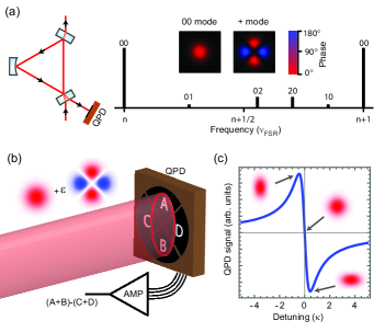
To understand the main stabilization method, one needs to recall the Hermite-Gaussian (HG) spatial modes supported by an optical cavity [25]. Here, of interest are the fundamental HG modes labeled ‘00’, and specific second-order HG modes that we label ‘+’ (Fig. 1a). A slightly elliptical beam with a horizontal/vertical orientation can mathematically be decomposed into a main ‘00’ component and a small ‘+’ component (Fig. 1b). For such a beam, the phase difference between these two components encodes the information about ellipticity. When incident on the cavity near a ‘00’ resonance, only the ‘00’ component builds up inside the cavity, acquiring a phase shift in the process, and giving rise to a change in the relative phase between the two components outside of the cavity. Through this mode-dependent phase shift, the reflected beam can be made to acquire opposite ellipticities on opposite sides of the resonance (Fig. 1c). From the perspective of cavity design, the only requirement for proper operation is for the ‘00’ mode not to be spectrally degenerate with the second-order modes. To harness this effect we use a quadrant photodiode (QPD), subtracting the sums of the diagonals to obtain an error signal proportional to beam ellipticity (Fig. 1b&c; see SM [24]). Specifically, the generated error signal is given by the imaginary part of the reflection coefficient in Eqn. 1.
The detected signal can be thought of as an interference between the resonating ‘00’ mode that leaks out of the cavity, and the second-order ‘+’ mode that promptly reflects from the cavity to form a phase reference. This detection modality is insensitive to alignment drifts and fluctuations, since small misalignments simply generate first-order modes in the mode decomposition [18]. A limitation to stability is still posed, for example, by residual fluctuations in the incident beam shape, attributable to the alteration of second-order mode components – affecting the phase reference. To help alleviate this residual limitation, we utilize the polarization pre- and post-selection procedure, which we efficiently describe using the weak-value concept [27]. This concept has been utilized over the last decade to amplify small signals in optical settings [28, 29, 30, 31] with mostly a good understanding of its benefits [32, 33].
Intuitively, the post-selection process allows one to directly perform a differential measurement between the signals that would be generated by the two polarization components of light incident on the cavity – through interference of amplitudes from the two polarizations. With polarization-resolved cavity resonances, one polarization can build up resonantly in the cavity while the other polarization reflects promptly, serving as a reference for the noise originating prior to the cavity. The differential measurement implemented by the post-selection then isolates the cavity signal. The post-selection setting adapted below enforces a complete destructive interference between the two amplitudes when the cavity is exactly on resonance. The description of this phenomenon takes the form of an effective loss-tunable cavity.
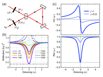
With the polarization degree of freedom included, the cavity reflection coefficient is replaced by a reflection operator acting on the input polarization state . When a post-selection onto state is made, the resulting effective reflection coefficient (Fig. 2a) is given by the weak-value of the reflection operator (see SM [24]):
| (1) |
Here is the laser-cavity frequency detuning, is the full-width cavity linewidth, and . The parameter is a dimensionless constant characterizing the roundtrip losses in the cavity, where , , and can be identified respectively with the under-coupled, impedance-matched, over-coupled, and cavity-gain regimes. The ‘amplification’ parameter depends on the specific post-selection, and it is real-valued for linear polarization states and . While it is a function of polarizer angles, operationally it can be related to the remaining power fraction after post-selection when the light is off-resonant (see SM [24]). The right hand side of Eqn. 1 is of the same form as the reflection from a regular high-finesse cavity, except with a variable loss parameter (at fixed ) instead if the fixed parameter . We demonstrate the variability of experimentally in Figure 2b by observing the post-selection dependence of the reflected power from the cavity.
Tuning the post-selection to the effective impedance-matched (Fig. 2c) configuration reduces noise for frequency stabilization purposes. In this configuration, the non-signal-generating beam components incident on the QPD are strongly attenuated while signal generating parts are attenuated less, effectively increasing error signal slope and reducing sensitivity to beam shape or intensity fluctuations (see SM [24]).
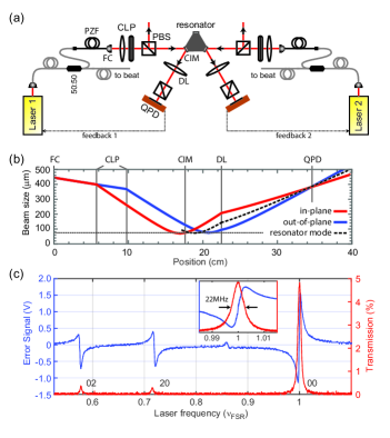
To demonstrate the performance of our stabilization scheme, we build two identical copies of the locking setup (Fig. 3a), and stabilize two separate lasers to two degenerate counter-propagating ‘00’ modes of a triangular ring cavity (see SM [24]). To assess stability, we split-off 50% of the power from the lasers to monitor the beating frequency of the lasers on a fast photodiode using a frequency counter (SRS FS740).
The implementation of the locking scheme relies on beam shaping for achieving opposite beam ellipticities on opposite sides of the resonance (Fig. 1c). This goal requires the phase difference between the ‘00’ and the ‘+’ components of the beam at the QPD location to be radians when the frequency is matched to the ‘00’ resonance. In this configuration the interference of the two components results into a circular beam profile at the QPD, yielding a zero error signal. When the frequency is detuned from resonance, the reflected ‘00’ component acquires an additional phase shift determined by Eqn. 1, directly altering the phase difference at the QPD location. For detunings of opposite sign, the phase-shifted interference results into opposite beam ellipticities, yielding opposite sign error signals. Note that the phase shift recedes to its on-resonance value for large detunings, rendering the beam circular once more far off-resonance. This allows us to do alignment and tuning while off resonance.
The required beam shaping is achieved using a cylindrical lens pair (CLP), through which a circular input beam is astigmatically focused. The distance between the CLP determines the amount of light in the ‘+’ mode, amounting to 10% of the total power () in our demonstration. Lens positions are aligned such that, as the beam propagates it reaches back to a circular profile at the QPD location when the light is off-resonance (Fig. 3b). The size of this circular beam needs to match that of the forward-propagated cavity ‘00’ mode to maximize the signal. For additional details on the design principle of the CLP and its relation to the error signal size, see SM [24].
The cavity utilized in this work has a full-linewidth of 22- and a finesse of for the ‘00’ mode (and a corresponding free spectral range of ). Two independent external cavity diode lasers at are employed to probe the cavity. Each laser has an intrinsic-linewidth of . For a discussion on the effect of laser linewidths on performance, see SM [24]. A typical error signal from this setup is shown in Figure 3c as one varies the frequency of one of the lasers. For reference, the largest peak of the signal here corresponds to a beam aspect ratio of about 1.3. To independently lock the frequencies of the two lasers to a common resonance, the obtained error signals are fed back to the currents of the respective lasers through feedback controllers (see SM [24]).
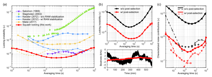
A comparison between different optical frequency stabilization systems can be made by characterizing the performance as a fractional instability with respect to the cavity linewidth – nominally, absolute instabilities will scale proportional to the cavity linewidth since typical sources of problematic instabilities originate from fluctuations in the error signal shape. In Figure 4a, we present the performance of the implemented scheme while locked to a ‘00’ mode resonance, and compare it to the best known implementations of other stabilization methods. It can be seen that we enter the locking instability regime for averaging times between and , surpassing previous state-of-the-art, and reaching instability at averaging. The explicit improvement brought by the post-selection is also illustrated in Figure 4b. Note that prior to this work, the tightest demonstrated laser-cavity locking was achieved using the transmission modulation method [15] (Fig. 4a). For the PDH method, although recent engineering of RAM levels that are almost compatible with our obtained instabilities were reported [34, 35] (Fig. 4a, dashed and dotted lines respectively), a demonstration of an actual laser-cavity locking at such levels had not been reported.
A characterization of various noise sources (Fig. 4c; see SM [24]) reveals that the residual fluctuations of the incident beam shape constitutes the dominant limitation to the currently achieved instability level. A major source of this instability is the thermal-stress induced polarization changes inside the launching fibers, which we observed to directly translate into beam ellipticity fluctuations. In fact, we note that switching from polarization maintaining fibers to polarizing fibers (Fig. 3a) had provided nearly an order of magnitude improvement, allowing us to reach the current results. Further stability improvements will require better control over the input beam shape stability. For the effects of the long-term temperature drifts on stability, see SM [24].
A generic optical-cavity application can integrate ‘squash locking’ as a plug-and-play method, benefiting from simplicity, robustness and performance. The lack of RF modulation, which avoids spectral contamination and electromagnetic interference, makes the technique particularly suited for applications like optical frequency conversion [36] or stabilization of laser injection locking [37]. For high-performance applications, such as space-based laser ranging (including gravitational wave detection) or development of optical frequency standards [9], there are often additional requirements which the technique is capable of delivering: Direct compatibility with low-light level measurements (see SM [24]), and direct integration compatibility with ultralow-vibration-sensitivity cavities (see SM [24]). Recently, utilizing the ‘tilt locking’ technique [18], a modulation-free laser locking system for ranging applications was demonstrated [38], showing compatibility with demanding space mission requirements. With the current technique, such systems could be implemented or improved more easily. Lastly, given its direct compatibility with on-chip systems such as dielectric whispering-gallery cavities (see SM [24]), the technique can benefit industrial optical communication systems requiring narrow linewidth lasers [39].
Acknowledgements.
This work is supported by IST Austria. We thank Rishabh Sahu and Sebastian Wald for technical contributions to the experiment.References
- Bloom et al. [2014] B. J. Bloom, T. L. Nicholson, J. R. Williams, S. L. Campbell, M. Bishof, X. Zhang, W. Zhang, S. L. Bromley, and J. Ye, An optical lattice clock with accuracy and stability at the 10-18 level, Nature 506, 71 (2014).
- Abbott et al. [2016] B. Abbott et al. (LIGO Scientific Collaboration and Virgo Collaboration), Observation of gravitational waves from a binary black hole merger, Phys. Rev. Lett. 116, 061102 (2016).
- Gürlebeck et al. [2018] N. Gürlebeck, L. Wörner, T. Schuldt, K. Döringshoff, K. Gaul, D. Gerardi, A. Grenzebach, N. Jha, E. Kovalchuk, A. Resch, T. Wendrich, R. Berger, S. Herrmann, U. Johann, M. Krutzik, A. Peters, E. M. Rasel, and C. Braxmaier, Boost: A satellite mission to test lorentz invariance using high-performance optical frequency references, Phys. Rev. D 97, 124051 (2018).
- Rudolph et al. [2020] J. Rudolph, T. Wilkason, M. Nantel, H. Swan, C. M. Holland, Y. Jiang, B. E. Garber, S. P. Carman, and J. M. Hogan, Large momentum transfer clock atom interferometry on the 689 nm intercombination line of strontium, Phys. Rev. Lett. 124, 083604 (2020).
- Hosten et al. [2016] O. Hosten, N. J. Engelsen, R. Krishnakumar, and M. A. Kasevich, Measurement noise 100 times lower than the quantum-projection limit using entangled atoms, Nature 529, 505 (2016).
- Kuhn et al. [2015] S. Kuhn, P. Asenbaum, A. Kosloff, M. Sclafani, B. A. Stickler, S. Nimmrichter, K. Hornberger, O. Cheshnovsky, F. Patolsky, and M. Arndt, Cavity-assisted manipulation of freely rotating silicon nanorods in high vacuum, Nano Letters 15, 5604 (2015).
- Aspelmeyer et al. [2014] M. Aspelmeyer, T. J. Kippenberg, and F. Marquardt, Cavity optomechanics, Rev. Mod. Phys. 86, 1391 (2014).
- Kessler et al. [2012] T. Kessler, C. Hagemann, C. Grebing, T. Legero, U. Sterr, F. Riehle, M. J. Martin, L. Chen, and J. Ye, A sub-40-mHz-linewidth laser based on a silicon single-crystal optical cavity, Nature Photonics 6, 687 (2012).
- Matei et al. [2017] D. G. Matei, T. Legero, S. Häfner, C. Grebing, R. Weyrich, W. Zhang, L. Sonderhouse, J. M. Robinson, J. Ye, F. Riehle, and U. Sterr, lasers with sub-10 mHz linewidth, Phys. Rev. Lett. 118, 263202 (2017).
- Barger et al. [1973] R. L. Barger, M. Sorem, and J. Hall, Frequency stabilization of a cw dye laser, Applied Physics Letters 22, 573 (1973).
- Hänsch and Couillaud [1980] T. Hänsch and B. Couillaud, Laser frequency stabilization by polarization spectroscopy of a reflecting reference cavity, Optics Communications 35, 441 (1980).
- Asenbaum and Arndt [2011] P. Asenbaum and M. Arndt, Cavity stabilization using the weak intrinsic birefringence of dielectric mirrors, Opt. Lett. 36, 3720 (2011).
- Moriwaki et al. [2009] S. Moriwaki, T. Mori, K. Takeno, and N. Mio, Frequency Discrimination Method Making Use of Polarization Selectivity of Triangular Optical Cavity, Applied Physics Express 2, 016501 (2009).
- White [1965] A. White, Frequency stabilization of gas lasers, IEEE Journal of Quantum Electronics 1, 349 (1965).
- Salomon et al. [1988] C. Salomon, D. Hils, and J. L. Hall, Laser stabilization at the millihertz level, J. Opt. Soc. Am. B 5, 1576 (1988).
- Drever et al. [1983] R. W. P. Drever, J. L. Hall, F. V. Kowalski, J. Hough, G. M. Ford, A. J. Munley, and H. Ward, Laser phase and frequency stabilization using an optical resonator, Applied Physics B 31, 97 (1983).
- Wieman and Gilbert [1982] C. E. Wieman and S. L. Gilbert, Laser-frequency stabilization using mode interference from a reflecting reference interferometer, Opt. Lett. 7, 480 (1982).
- Shaddock et al. [1999] D. A. Shaddock, M. B. Gray, and D. E. McClelland, Frequency locking a laser to an optical cavity by use of spatial mode interference, Opt. Lett. 24, 1499 (1999).
- Miller and Evans [2014] J. Miller and M. Evans, Length control of an optical resonator using second-order transverse modes, Opt. Lett. 39, 2495 (2014).
- Zullo et al. [2016] R. Zullo, A. Giorgini, S. Avino, P. Malara, P. D. Natale, and G. Gagliardi, Laser-frequency locking to a whispering-gallery-mode cavity by spatial interference of scattered light, Opt. Lett. 41, 650 (2016).
- Zhang et al. [2014] W. Zhang, M. J. Martin, C. Benko, J. L. Hall, J. Ye, C. Hagemann, T. Legero, U. Sterr, F. Riehle, G. D. Cole, and M. Aspelmeyer, Reduction of residual amplitude modulation to 1×10⁻⁶ for frequency modulation and laser stabilization, Opt. Lett. 39, 1980 (2014).
- Sheard et al. [2010] B. Sheard, G. Heinzel, and K. Danzmann, LISA long-arm interferometry: an alternative frequency pre-stabilization system, Classical and Quantum Gravity 27, 084011 (2010).
- Świerad et al. [2016] D. Świerad, S. Häfner, S. Vogt, B. Venon, D. Holleville, S. Bize, A. Kulosa, S. Bode, Y. Singh, K. Bongs, E. M. Rasel, J. Lodewyck, R. Le Targat, C. Lisdat, and U. Sterr, Ultra-stable clock laser system development towards space applications, Scientific Reports 6, 33973 (2016).
- [24] See Supplemental Material at XXX .
- Siegman [1986] A. E. Siegman, Lasers (University Science Books, 1986).
- Slagmolen et al. [2002] B. Slagmolen, D. Shaddock, M. Gray, and D. McClelland, Frequency stability of spatial mode interference (tilt) locking, IEEE Journal of Quantum Electronics 38, 1521 (2002).
- Aharonov et al. [1988] Y. Aharonov, D. Z. Albert, and L. Vaidman, How the result of a measurement of a component of the spin of a spin-1/2 particle can turn out to be 100, Phys. Rev. Lett. 60, 1351 (1988).
- Hosten and Kwiat [2008] O. Hosten and P. Kwiat, Observation of the Spin Hall Effect of Light via Weak Measurements, Science 319, 787 (2008).
- Dixon et al. [2009] P. B. Dixon, D. J. Starling, A. N. Jordan, and J. C. Howell, Ultrasensitive beam deflection measurement via interferometric weak value amplification, Phys. Rev. Lett. 102, 173601 (2009).
- Starling et al. [2010] D. J. Starling, P. B. Dixon, A. N. Jordan, and J. C. Howell, Precision frequency measurements with interferometric weak values, Phys. Rev. A 82, 063822 (2010).
- Xu et al. [2013] X.-Y. Xu, Y. Kedem, K. Sun, L. Vaidman, C.-F. Li, and G.-C. Guo, Phase estimation with weak measurement using a white light source, Phys. Rev. Lett. 111, 033604 (2013).
- Jordan et al. [2014] A. N. Jordan, J. Martínez-Rincón, and J. C. Howell, Technical advantages for weak-value amplification: When less is more, Phys. Rev. X 4, 011031 (2014).
- Torres and Salazar-Serrano [2016] J. P. Torres and L. J. Salazar-Serrano, Weak value amplification: a view from quantum estimation theory that highlights what it is and what isn’t, Scientific Reports 6, 19702 (2016).
- Matei et al. [2016] D. G. Matei, T. Legero, C. Grebing, S. Häfner, C. Lisdat, R. Weyrich, W. Zhang, L. Sonderhouse, J. M. Robinson, F. Riehle, J. Ye, and U. Sterr, A second generation of low thermal noise cryogenic silicon resonators, Journal of Physics: Conference Series 723, 012031 (2016).
- Jin [2021] L. Jin, Suppression of residual amplitude modulation of adp electro-optical modulator in Pound-Drever-Hall laser frequency stabilization, Optics & Laser Technology 136, 106758 (2021).
- Shaddock et al. [2000] D. A. Shaddock, B. C. Buchler, W. P. Bowen, M. B. Gray, and P. K. Lam, Modulation-free control of a continuous-wave second-harmonic generator, Journal of Optics A: Pure and Applied Optics 2, 400 (2000).
- Ottaway et al. [2001] D. Ottaway, M. Gray, D. Shaddock, C. Hollitt, P. Veitch, J. Munch, and D. McClelland, Stabilization of injection-locked lasers using spatial mode interference, IEEE Journal of Quantum Electronics 37, 653 (2001).
- Chabbra et al. [2021] N. Chabbra, A. R. Wade, E. R. Rees, A. J. Sutton, A. Stochino, R. L. Ward, D. A. Shaddock, and K. McKenzie, High stability laser locking to an optical cavity using tilt locking, Opt. Lett. 46, 3199 (2021).
- Al-Taiy et al. [2014] H. Al-Taiy, N. Wenzel, S. Preußler, J. Klinger, and T. Schneider, Ultra-narrow linewidth, stable and tunable laser source for optical communication systems and spectroscopy, Opt. Lett. 39, 5826 (2014).