Feedforward PID Control of Full-Car with Parallel Active Link Suspension for Improved Chassis Attitude Stabilization
Abstract
PID control is commonly utilized in an active suspension system to achieve desirable chassis attitude, where, due to delays, feedback information has much difficulty regulating the roll and pitch behavior, and stabilizing the chassis attitude, which may result in roll over when the vehicle steers at a large longitudinal velocity. To address the problem of the feedback delays in chassis attitude stabilization, in this paper, a feedforward control strategy is proposed to combine with a previously developed PID control scheme in the recently introduced Parallel Active Link Suspension (PALS). Numerical simulations with a nonlinear multi-body vehicle model are performed, where a set of ISO driving maneuvers are tested. Results demonstrate the feedforward-based control scheme has improved suspension performance as compared to the conventional PID control, with faster speed of convergence in brake in a turn and step steer maneuvers, and surviving the fishhook maneuver (although displaying two-wheel lift-off) with 50 mph maneuver entrance speed at which conventional PID control rolls over.
I INTRODUCTION
The suspension system refers to the entire support system consisting of springs and shock absorbers between the vehicle body and tires. The function of the suspension system is to support the body, and improve ride comfort and road holding [1]. The passive suspension is a combination of mechanical components such as springs and dampers, which can only store or dissipate energy. In the modern car market with fierce competition, the performance of passive suspension is beginning to have difficulty to meet customers’ demand in more efficient systems and growing requirements in high-quality ride comfort and road holding automobile performance. Active suspensions started to appear with chassis leveling, vibration attenuation, as well as low energy costs and high reliability requirements, which are compatible with the future electric vehicles.
Many advanced control approaches have been proposed for automobile semi-active and active suspension systems in the past few decades and achieved substantial results. The optimized sliding mode control algorithm combining linear quadratic optimal control algorithm is proposed in [2] to improve active suspension performance. In [3], an active suspension control method based on the multi-agent prediction algorithm is proposed to attenuate the vertical acceleration of the suspension body. A robust optimal control method is designed for the suspension system in [4] to improve the vehicle performances in terms of handling stability and riding comfort. An active suspension controller based on feedback control for half-vehicle model is proposed in [5] to improve the vehicle ride comfort. The Linear parameter varying (LPV) feedforward filter is designed with a preexisting full-vehicle LPV controller in [6] to improve the stability of a vehicle subject to driver-induced roll disturbances. The feedforward compensation control based on steering angle is proposed in [7] to apply an anti-roll moment in advance which prevents the rollover. Apart from the control methods, many mechanical structures of active suspension are widely studied in automotive industry. Bose was first to develop electromagnetic actuators to replace the conventional spring-dampers [8]. Audi A8 introduced the adaptive air suspension, which combines a high-end air suspension with controlled damping. It enables the luxury sedan to remain composed and smooth on all types of uneven road surfaces [9]. The adaptive M suspension developed by BMW use electronically controlled shock absorbers and sensors to calculate the optimal damping forces in a few milliseconds [10]. Mercedes-Benz introduced its Active Body Control (ABC) using hydro-pneumatic suspension [11].
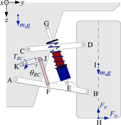
Recently, a novel mechatronic suspension solution, the Parallel Active Link Suspension (PALS), has been proposed in [12, 13]. As shown in Fig. 1, in the PALS the rocker-pushrod assembly (‘K-J-F’) is introduced between the chassis and the lower wishbone (’A-B’), and in parallel with the spring-damper unit (’G-E’). The active segment the rocker (‘K-J’), is driven by a rotary permanent magnet synchronous motor (PMSM) actuator, which delivers a torque () acting from the chassis onto the lower wishbone (via the pushrod) to improve the performance of a double-wishbone suspension. The PALS features i) negligible unsprung mass and small sprung mass increment, ii) low power actuation requirements, with the efficient influence on the vertical tire force increment due to PALS links geometrically optimization and mechanical implementation, iii) simplified structure by the replacement of the anti-roll bar, iv) fail-safe characteristics and v) employment of developed and compact rotary-electromehcanical-actuation mechanics.
Previous work develops the steady-state analysis for the PALS potential in terms of the chassis leveling and proposes the multi-objective PID control for the minimization of both the roll and pitch angles [13]. However, despite these achievements, the previous work does not account for the delay due to the feedback control, which may result in the deterioration of the chassis attitude stabilization. This paper builds two compensation models to compensate the vertical tire force and tackle the feedback control delay through applying the feedforward control with an accurate nonlinear simulation fit based compensation model utilized. The main contributions of this paper are: i) development of two compensation models based on full car steady state analysis and nonlinear simulation fitting, respectively, and selection of the best performing compensation model by comparison of their fitting accuracy, ii) the design of ‘feedforward-PID’ control that combines the nonlinear simulation fit based compensation model developed above with regular PID control, iii) numerical simulations with a nonlinear multi-body model of the PALS-retrofitted SUV full car to assess the effectiveness and robustness of the proposed control scheme, as compared to the passive suspension and the actively controlled PALS by conventional robust control, while the vehicle undergoes different ISO-defined road events. The rest of the paper is organized as follows: Section II illustrates the derivation of the feedforward normal load compensation with polynomial fitting method applied in the nonlinear simulation environment, and with steady state analysis of the full car. Section III introduces a feedforward PID control scheme based on nonlinear simulation fit based compensation model. Section IV performs numerical simulations to assess the performance of the proposed control scheme by comparing the proposed feedforward-PID scheme with conventional PID control in terms of pitch and roll angle minimization. Finally, concluding remarks are discussed in Section V.
II Development of tire force compensation model
In this section, the mathematical steady-state model of the PALS-retrofitted full car that is developed in [13] is briefly illustrated first, which motivates the proposal of one of the feedforward compensation laws. The other feedforward compensation law is introduced based on the relationship obtained by applying polynomial fitting through simulation of nonlinear full car model.
II-A Full car Steady state model and analysis
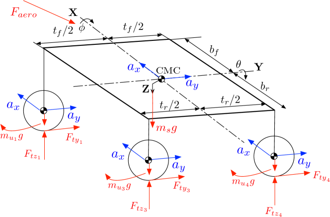
As it can be shown in Fig. 1, the vertical tire force at any given corner can be estimated as follows:
| (1) |
where is the vertical tire force in the nominal configuration, and represent the vertical tire force increments due to longitudinal and lateral acceleration, respectively, and is the force increment caused by the change in aerodynamic force .
For the equilibrium of vertical forces to hold for the whole vehicle and for each axle independently, the following relationships must be satisfied:
| (2) | ||||
where the right subscript refers to the corner number 1 to 4 denoting the front left, front right, rear left and rear right corners, respectively. The vertical tire force increment due to vehicle longitudinal acceleration is obtained by the balance of pitching moments :
| (3) |
where and correspond to the front and rear unsprung mass, respectively, which are not supported by the springs, to the sprung mass which is the rest of the mass of the car, to the height above the ground of the center of the mass of the chassis, and to the front and rear wheelbase and and to the front and rear wheel radius, respectively.
Similarly, the vertical tire force increment influenced by lateral acceleration can be estimated through the balance of rolling moments:
| (4) | ||||
where is defined as the ratio of overturning distribution (OCD) provided by the rear axle.
The vertical tire force increment on both front and rear axles caused by their aerodynamics force can be calculated through:
| (5) | |||
where and are the aerodynamic downforce coefficients for the front and rear axles, respectively, and is the longitudinal velocity of the vehicle.
Based on the steady state vertical tire forces of the full car provided in (1)-(5), the chassis leveling capability of PALS can be achieved as follows.
Applying the principle of virtual work to a corner of the car with rocker-pushrod and the double wishbone linkages with the road wheel taken into account and considering a static chassis yields
| (6) |
where is the vertical coordinate of the road wheel center, is the rocker angle with respect to the horizontal line, is the suspension deflection, and is the linear equivalent actuation force.
Transformation functions between and at each corner can be defined as follows:
| (7) |
For the feedback control system, the controller does not work well until the deviation of the roll angle reaches an ultimate value. However, it is hard to regulate the system when the roll angle deviation is large or the roll rate is increasing which may result in rollover. Therefore, the vehicle’s longitudinal and lateral acceleration shown in (3)-(4) are estimated according to the steering wheel angle, longitudinal speed, gas pedal and brake pedal position. Then, the active suspension produces the vertical tire force in advance to ensure that both roll and pitch angle are minimized.
II-B Nonlinear simulation fit based compensation model
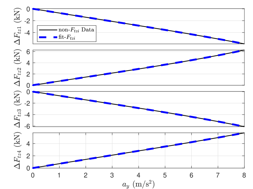
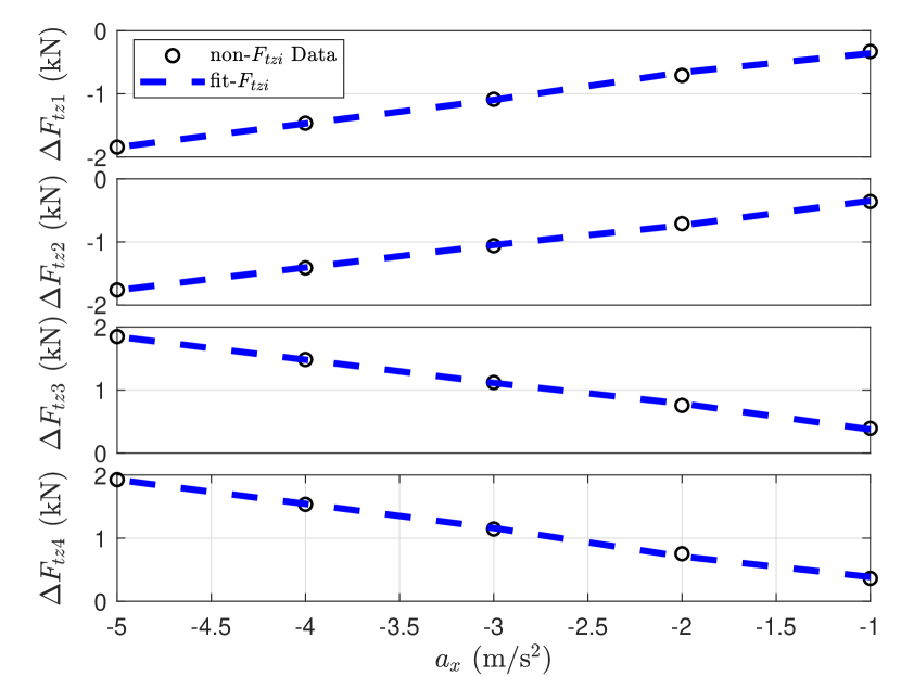
In addition to the steady state model utilized in [13], a new practical approach is introduced in this section which uses a polynomial fitting method in the nonlinear simulation of a high fidelity nonlinear multi-body model developed in [13] to establish the relationship between longitudinal acceleration (), lateral acceleration () and the vertical tire force increments () at each corner. The approach is detailed as follows: i) The steady state cornering maneuver is selected to find the relationship between and only, due to the linear growth of with constant ; ii) similarly, with initial longitudinal speed = 100 km/h, the straight line constant deceleration maneuver is applied to establish the relationship between and . The plots of the aforementioned with regards to and are shown in Fig. 2 and Fig. 3, respectively.
To achieve the best fitting, is selected as a third order polynomial fitting and is chosen as first order polynomial fitting. Hence, the total vertical tire force increment of the selected compensation model is derived as follows:
| (8) |
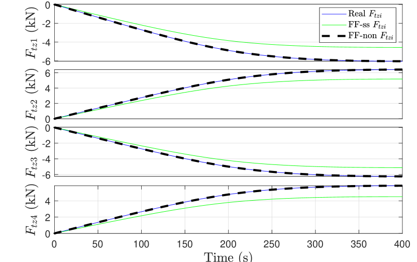
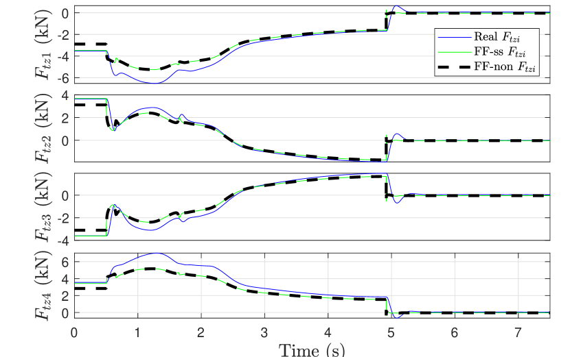
The comparison of vertical tire force increments between the steady state model and the nonlinear simulation fit model in terms of steady state cornering and brake in turn ISO maneuvers are shown below in Fig. 4 and Fig. 5. As it can be seen in these two plots, although the steady state model provides the information on through (1)-(5), the nonlinear simulation fit model offers more accurate results for . Therefore, the nonlinear simulation fit model is selected as the compensation model.
III Control Methodology Development
This section describes the synthesis of the two control schemes with PALS for the chassis leveling contributed by the present work: A) the previously proposed multi-objective PID control [13], and B) the newly proposed feedforward PID control based on nonlinear simulation fit, which is detailed in sec.II-B.
III-A PID control (‘PALS-PID’)
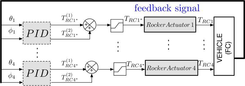
To achieve desirable chassis attitude and driving dynamics, the multi-objective PID control scheme (‘PALS-PID’) is adapted to the PALS-retrofitted full car [13]. As it can be shown in Fig. 6, a group of PID controllers at each corner , are synthesized to deal with pitch and roll angle control, with and denoting feedback signals. The reference rocker torque with pitch angle minimization, at each corner is obtained as follows:
| (9) | ||||
and the reference rocker torque with roll angle minimization is:
| (10) | ||||
with the PID tuning parameters detailed in Table II. The overall reference rocker torque feeding the rotary rocker actuator at each corner is:
| (11) |
Through the inner-loop tracking control at each corner, the is transformed to and then fed to the vehicle system which is detailed in [13].
III-B Nonlinear Feedforward PID (‘FF-PID-non’)
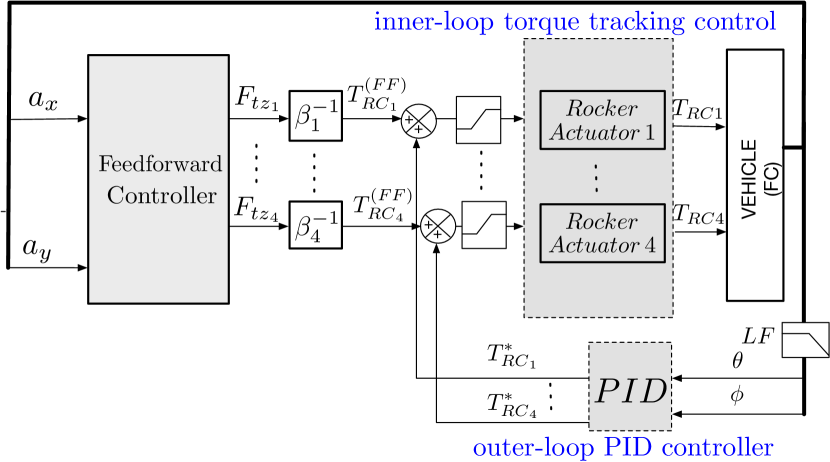
The previous multi-objective PID control loop regulates the output pitch and roll angle of the vehicle plant employing negative feedback. On the other hand, as shown in Fig. 7, with both longitudinal and lateral acceleration measured from the vehicle, the nonlinear Feedforward PID control approach utilizes the feedforward compensation law, proposed in Section II-B.A, to calculate the vertical tire force . Through the conversion block in (7), the are obtained to achieve major compensation of the actuation torques of the rotary actuators. Usually, the feedforward control cannot directly compensate the full information of the output rocker torque and therefore requires combining with the PID feedback control loops. Then the inner loop rocker torque tracking control links the feedforward control and the mechanical system of the PALS full car, where d-q transformation and zero d-axis current controls proposed in [13] are utilized, such that the three-phase PMSMs behave as DC equivalent motors, with the produced torques proportional solely to the q-axis currents.
It is notable that the PID parameters should be retuned in nonlinear feedforward PID (listed in Table II in the Appendix) as compared to those in ‘PALS-PID’ due to the effect of the feedforward control. However, this tuning for PID is time-efficient since feedforward control accounts for nearly 90% of the total , making the PID contribute only marginally to the regardless of aggressive tuning selection.
IV Numerical Simulations with nonlinear multi-body model and analysis
In this section, with the nonlinear multi-body model described in [13] and the control strategies proposed in Section III, a group of ISO driving maneuvers, containing, A) step steer, B) steady-state cornering, C) brake in a turn, D) pure longitudinal braking and acceleration, E) fishhook, and F) continuous sinusoid steer, are tested to evaluate the efficiency and robustness of the synthesized controllers (’PALS-PID’ synthesized in Section III-A and ’FF-PID-non’ synthesized in Section III-B).
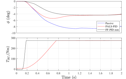
IV-A Step Steer
ISO 7401:2011 details an open-loop test method to determine the transient response behavior of passenger vehicles [15]. Here, the PALS-retrofitted full car is driven at a constant forward speed of 100 km/h, with the steering wheel angle increasing at a constant rate of 500 deg/s from 0 to 48.6 such that the vehicle stabilizes at a lateral acceleration of = 8 m/s2. The reduction in roll angle achieved thanks to the synthesized controllers is presented in Fig. 8, where ‘PALS-PID’ provides 42% mitigation of roll angle RMS value over the passive suspension. The ‘FF-PID-non’ produces even better performance in terms of roll angle RMS value attenuation than ‘PALS-PID’, with 52% mitigation of roll angle over the passive suspension. Furthermore, it does not suffer as the ‘PALS-PID’ does from a positive roll angle slope at approximately 0.7 s, and as Fig. 8 shows, the response of ‘FF-PID-non’ is much faster than that of ‘PALS-PID’ in terms of front-left corner rocker torque .
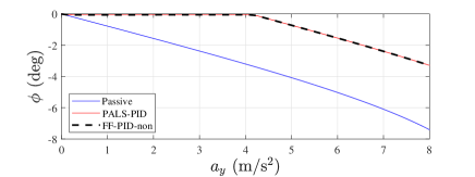
IV-B Steady State Cornering
ISO 4138:2004 defines an open-loop test method to assess the potential of the passenger vehicles for roll mitigation in steady-state circular driving [16].
The vehicle is driven at a constant longitudinal speed of 100 km/h, with the angle of the steering wheel linearly increased from 0 to 60 in 400 s. Fig. 9 depicts that the roll angle is completely neutralised up to lateral accelerations of approximately 4 m/s2 for ‘PALS-PID’. The ‘FF-PID-non’ control strategy presents the same performance enhancement over the passive suspension as ‘PALS-PID’, due to the successful tracking of the saturating reference actuation forces.
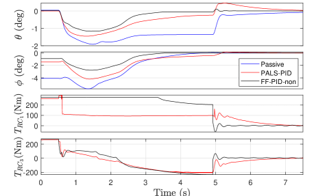
IV-C Brake in a turn
ISO 7975:2006 presents an open-loop test method for determining the steady-state circular response of a vehicle that is altered by a sudden brake. As defined in [17], the PALS-retrofitted full car is initially driven in a circular path of 100 m radius at a constant lateral acceleration of 5 m/s2, corresponding to a constant forward speed of 80 km/h, then the steering wheel is fixed and brakes applied to enable the vehicle to slow down at a constant deceleration of 5 m/s2.
The variations of the roll angle, , and pitch angle, , are shown in Fig. 10. It can be seen that, as compared to the passive suspension, the ‘PALS-PID’ has less overshoot but it takes a longer time to settle in terms of roll angle performance, and its average pitch angle is reduced from -1.5 to -0.4 with a larger overshoot at approximately 5 s before it comes to a stop. ‘FF-PID-non’ has a similar performance to that of ‘PALS-PID’ with slightly smaller overshoot over an initial time period of 0-2 s in terms of pitch angle performance, then it converges much faster to zero without suffering as the ‘PALS-PID’ does from a positive pitch angle spike at approximately 5 s when the car comes to a stop and restores its equilibrium position; and its roll angle is reduced with a much smaller overshoot at approximately 1.5 s and shorter time to settle as compared to ‘PALS-PID’. Fig. 10 also shows the plots of the rocker torque of front left corner () and rear left corner (). As it can be seen, the response of ‘FF-PID-non’ is much faster than that of ‘PALS-PID’ in terms of stopping the vehicle.
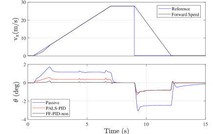
IV-D Pure longitudinal acceleration and braking
The pure longitudinal accelerating and braking maneuver is used to assess the ability of the controlled system for pitch mitigation. In this maneuver, a hard acceleration process starts from 1 km/h to 100 km/h in 6.5 s, which is then followed by a 2 s constant speed period and an emergency stop. Time responses for the PALS full car in this maneuver are shown in Fig. 11. In the top row, the reference and actual speed profiles are compared. As it can be seen, the car follows the acceleration profile closely, and the resulting deceleration rates remain within the 1.05 g to 1.25 g band during the emergency stop. Pitch angle simulation results for different controllers are displayed in the bottom row of Fig. 11, which shows that the ‘PALS-PID’ is capable of maintaining an overall flat pitch angle during the acceleration phase and achieves approximately 35% pitch angle correction during the emergency stop. The ‘FF-PID-non’ achieves almost of the average pitch angle during the acceleration phase and marginally better response during emergency stop as compared to ‘PALS-PID’.
IV-E Fishhook
The fishhook defines an open-loop test procedure to evaluate the vehicle dynamic rollover propensity [18].
The test procedure consists of two stages. In the first one, the PALS-retrofitted full car is driven at a forward speed of 50 miles per hour (mph), while a slow turning maneuver is performed to determine the steering wheel angle required to reach a lateral acceleration of 0.3 g. In the second stage, the vehicle is driven in a straight line at a certain Maneuver Entrance Speed (MES). Then, the throttle pedal is released, and the steering-wheel angle is rotated up to . The steering wheel angle is reversed to - when the roll rate reduces below 1.5 deg/s, staying there for 3 s, after which it reverts to zero over a time period of 2 s. The first manoeuvre is performed with MES=35 mph, then it is repeated with MES=40, 45 and 50 mph.
The passive car survives the fishhook with MES = 35mph, but suffers from rollover at MES = 40mph. The PALS-retrofitted full car with ‘PALS-PID’ control manages to avoid rollover at MES = 40mph and MES = 45mph, while it cannot maintain the roll angle stability at MES = 50mph. In contrast, the feedforward control strategy ‘PALS-PID-non’ is capable of presenting robust and stable performance for all four test values of MES.
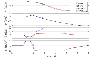
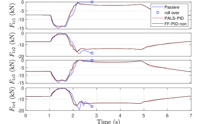
Results for MES = 40mph are presented in the first column of Fig. 12 for the passive and active configurations. In the top-left plot of Fig. 12, both active controllers keep the roll angle below 5 deg in the first steering phase, and the roll angle peaks at around 5 deg in the second. The forward speed, yaw angle and lateral acceleration are also included in the plots to help understand the overall performance. The results of vertical tire force at each corner with different controllers are shown in the bottom-left plot of Fig. 12. The passive suspension displays two-wheel lift at the point indicated by blue circles, and eventually rolls over. The other two active controllers also display two-wheel lift at t = 2.23 s, but regain contact with the ground quickly at t = 2.29 s and remain stable throughout the maneuver.
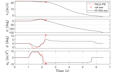
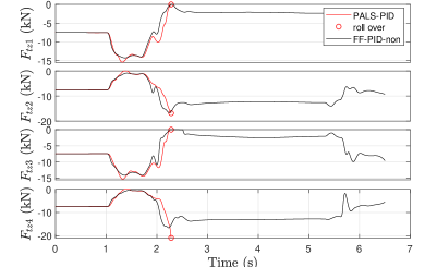
Results for MES = 50mph are shown in the second column of Fig. 13 for active configurations only. The chassis parameters including forward speed, yaw angle, roll angle and lateral acceleration are displayed in the top-right plot of Fig. 12. It is clear that ‘PALS-PID-non’ keeps the roll angle below 5 deg throughout the maneuver. Two-wheel lift occurs at time t = 2.26s, but contact with the ground is reclaimed at time t = 2.38s and the vehicle remains stable until the end of the maneuver which can be verified in the bottom-right plot of Fig. 12. However, ‘PALS-PID’ displays two-wheel lift at t = 2.28s and finally rolls over.
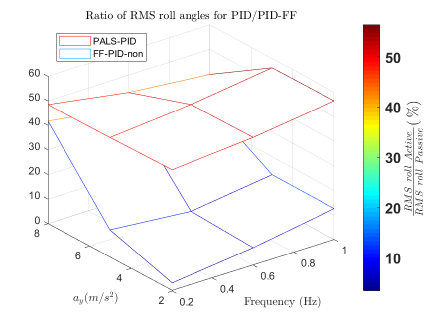
IV-F Continuous sinusoid steer
The continuous sinusoid steer defines an open-loop test procedure to understand the performance of the PALS at various frequencies.
A continuous steering-wheel sinusoid is applied when the vehicle is driven in a straight line at 100 km/h as defined in [15]. Steering frequencies from 0.2 Hz to 1 Hz in 0.2 Hz steps are applied and results obtained with different cases of active suspensions are compared with the passive suspension. The ratios of the RMS roll angle obtained with the two active suspension methods over the one computed with the passive suspension are shown in Fig. 13. This ratio remains around 50% in most of the cases for ‘PALS-PID’, while the ratio for the feedforward controller remains below 20% in most cases and rises to 40% at the whole steering frequency range and large steering-wheel amplitudes which indicate better performance in terms of chassis leveling than ‘PALS-PID’.
V Conclusion
The recently proposed mechatronic suspension of the Parallel Active Link Suspension (PALS) is investigated in the application to a SUV full car [13], with feedforward compensation taken into consideration in the suspension control design, revealing promising potential for chassis leveling and stabilization.
The proposed feedforward PID control strategy with nonlinear polynomial fitting method applied is proposed for PALS low-frequency application, with essential improvement over the passive suspension system and decent enhancement as compared to ‘PALS-PID’ in terms of chassis leveling and speed of convergence over a set of ISO driving maneuvers.
In future work, the PALS performance in higher-frequency road events is to be tested for the integration of control (-synthesis control) developed elsewhere and the proposed feedforward PID control. The ride comfort and road holding related variables (CMC vertical acceleration and the tire deflection) require a more comprehensive assessment of the PALS performance before any on-road experiments.
| Parameters | Value |
|---|---|
| Original vehicle [19, 13] | |
| CMC Height | 0.71 m |
| F/R Weight distribution | 50 / 50 |
| Total/Sprung mass | 2950 / 2700 kg |
| F/R OCD ratio (1 - / ) | 57 / 43 |
| F/R Spring stiffness | 53.5 / 53.1 |
| F/R Tire stiffness | 290 |
| F/R Tire damping | 300 |
| F/R Track width () | 1.677 / 1.696 |
| F/R Wheelbase () | 1.538 / 1.538 |
| F/R Wheel radius () | 0.385 / 0.385 |
| F/R Unsprung mass ( / ) | 62.5 / 62.5 kg |
| PALS retrofit (actuator per corner) [19, 13] | |
| FR Actuator mass | 12 kg |
| FR Gear Ratio | 66 |
| F/R Low speed shaft (LSS) | 166 / 165 |
| continuous torque | |
| F/R LSS peak torque | 273 / 273 |
| Controller | Aim | Axle | P | I | D |
|---|---|---|---|---|---|
| ‘PALS-PID’ | pitch | FR | 1000 | 20000 | 4 |
| roll | FR | 500 | 5000 | 4 | |
| ‘FF-PID-non’ | pitch | FR | 100 | 2500 | 2 |
| roll | FR | 50 | 1500 | 2 |
References
- [1] R. N. Jazar, Vehicle dynamics: theory and application. Springer, 2017.
- [2] S.-A. Chen, J.-C. Wang, M. Yao, and Y.-B. Kim, “Improved optimal sliding mode control for a non-linear vehicle active suspension system,” Journal of Sound and Vibration, vol. 395, pp. 1–25, 2017.
- [3] N. Zhang, Y. He, Y. Whang, and J. Whang, “Active suspension control based on multi-agent predictive algorithm,” in 2020 4th CAA International Conference on Vehicular Control and Intelligence (CVCI), pp. 354–358, IEEE, 2020.
- [4] R. Bai and H.-B. Wang, “Robust optimal control for the vehicle suspension system with uncertainties,” IEEE Transactions on Cybernetics, 2021.
- [5] X. Yang, Z. Wang, and Y. Lu, “Feedforward compensation control based on steering angle for vehicle roll stability,” in 2007 IEEE International Conference on Mechatronics, pp. 1–5, IEEE, 2007.
- [6] J. Zheng, X. Zong, and S. Ma, “Comfort control of active suspension based on state feedback,” in 2021 IEEE 5th Advanced Information Technology, Electronic and Automation Control Conference (IAEAC), vol. 5, pp. 143–147, IEEE, 2021.
- [7] M. Fleps-Dezasse, T. Bünte, F. Svaricek, and J. Brembeck, “Lpv feedforward control of semi-active suspensions for improved roll stability,” Control Engineering Practice, vol. 78, pp. 1–11, 2018.
- [8] T. Van der Sande, B. Gysen, I. Besselink, J. Paulides, E. Lomonova, and H. Nijmeijer, “Robust control of an electromagnetic active suspension system: Simulations and measurements,” Mechatronics, vol. 23, no. 2, pp. 204–212, 2013.
- [9] I. Adcock, “Audi details new a8 active suspension,” SAE International, vol. 14, 2017.
- [10] C. Lischka, “Business athlete–exciting driving dynamics for the all-new bmw 5 series,” in 8th International Munich Chassis Symposium 2017, pp. 83–103, Springer, 2017.
- [11] M. Becker, K.-P. Jaker, F. Fruhauf, and R. Rutz, “Development of an active suspension system for a mercedes-benz coach (o404),” in Proceedings of Joint Conference on Control Applications Intelligent Control and Computer Aided Control System Design, pp. 146–151, IEEE, 1996.
- [12] M. Yu, C. Arana, S. A. Evangelou, D. Dini, and G. D. Cleaver, “Parallel active link suspension: A quarter-car experimental study,” IEEE/ASME Transactions on Mechatronics, vol. 23, no. 5, pp. 2066–2077, 2018.
- [13] M. Yu, S. A. Evangelou, and D. Dini, “Parallel active link suspension: Full car application with frequency-dependent multiobjective control strategies,” IEEE Transactions on Control Systems Technology, pp. 1–16, 2021.
- [14] C. Arana, Active variable geometry suspension for cars. PhD thesis, Imperial College London, 2015.
- [15] ISO, “7401:2011,road vehicles–lateral transient response test methods–open-loop test methods,” 2011.
- [16] ISO, “4138: Passenger cars–steady-state circular driving behaviour–open-loop test methods,” ISO: Geneva, Switzerland, 2012.
- [17] ISO, “7975:2006,passenger cars – braking in a turn – open loop test procedure,” 2006.
- [18] N. H. T. S. Administration et al., “Laboratory test procedure for dynamic rollover: the fishhook maneuver test procedure,” Washington (DC): US, Department of Transportation, 2013.
- [19] C. Arana, S. A. Evangelou, and D. Dini, “Series active variable geometry suspension application to chassis attitude control,” IEEE/ASME Transactions on Mechatronics, vol. 21, no. 1, pp. 518–530, 2016.