Electron acceleration from the interaction of three crossed parallel Alfvén waves
Abstract
We study the non-linear interaction of three parallel Alfvén wave packets (AWP) in an initially uniform plasma using 2.5D particle-in-a-cell (PIC) numerical simulations. We aim to help to explain the observation of suprathermal electrons by multiple Alfvén waves collision in regions where these waves are trapped like IAR (Ionospheric Alfvén Resonator), Earth radiation belts or coronal magnetic loops. In the context of APAWI process that have been described by Mottez (2012, 2015), the interaction of two parallel Alfvén waves (AW) generates longitudinal density modulations and parallel electric field at the APAWI crossing region that can accelerate particles effectively in the direction of the background magnetic field. Our simulations show that when a third parallel AWP of different initial position arrives at the APAWI crossing region, it gives rise to a strong parallel electron beams () at longitudinal cavity density gradients. We suggest that velocity drift from outgoing AW generates interface waves in the transverse direction, which allows propagating waves to develop parallel electric fields by phase mixing process when of the wavy density gradient (oblique gradient) is in the range of the electron inertial length .
1 Introduction
Nonlinear interactions of Alfvén waves play a substantial role in the heating and acceleration of the solar corona and in the auroral acceleration of particles in Earth magnetosphere. The collision between counter-propagating Alfvén waves has been investigated in term of MHD and kinetic plasma by a number of authors (e.g., Zhao et al., 2011; Howes & Nielson, 2013; Nielson et al., 2013; Pezzi et al., 2017; Howes et al., 2018; Verniero & Howes, 2018). However, these studies have been focused mainly on the dynamics of turbulent energy transfer to the small perpendicular scales range.
Acceleration by Parallel Alfvén Waves Interactions (APAWI) described in Mottez (2012, 2015) is a process of nonlinear interaction of two Alfvén wave packets propagating mainly in opposite directions, in an initially uniform plasma, with their wave vectors parallel to the ambient magnetic field. The APAWI process causes a significant modulation of the plasma density giving rise to cavities and electron depletion at the waves crossing region. Alfvén waves with the same circular polarization can generate a parallel magnetic gradient and electric field accelerating electrons in the direction of ambient magnetic field. APAWI can take place in regions associated to trapped Alfvén waves like IAR (Ionospheric Alfvén Resonator) and radiation belts in Earth, or in magnetic loops in solar corona (see Mottez (2015) for discussions). However, in such plasma configuration, waves can suffer from several parallel reflections giving rise to more complex interactions. Therefore, unlike previous studies (Mottez, 2012, 2015) were only two sinusoidal waves or two wave packets were considered, we consider the interaction of a larger number of waves. For simplicity and to understand the basic physics of particle acceleration by multiple Alfvén wave collisions, we have carried out simulations of interaction of three parallel Alfvén waves.
We use a particle in cells (PIC) numerical simulation code (Mottez et al., 1998) to study the interaction of three parallel Alfvén waves packets in an initially homogeneous plasma. First, two wave packets interfere, and behave according to the APAWI process. Then, a third Alfvén wave packet arrives at the crossing region (inhomogeneous plasma) of the two initial Alfvén waves, which, as we will show, is equivalent to the interaction of a single Alfvén wave packet with an inhomogeneous plasma.
A phase-mixing process occurs when an Alfvén wave propagates through a density inhomogeneity that is transverse to the background magnetic field (Heyvaerts & Priest, 1983). Initially, the Alfvén wave propagates in a parallel direction () with a plane surface front. However, when it hits a perpendicular gradient of density like cavity (density depletion), the wavefront is distorted (phase mixing) because of the fast velocity propagation in the low density region than in the outside according to the Alfven velocity , where is the mass density and is the background magnetic field. Therefore the wavefront becomes oblique to the parallel magnetic field and develops a perpendicular wave vector along the transverse density gradients as well as small perpendicular scales. When this transverse scale is of order of the electron inertial length () in the inertial regime where ( is the ratio kinetic pressure over the magnetic pressure), the AW develops a parallel electric field in strong density gradient regions which accelerates electrons in the parallel direction (Génot et al., 1999). The parallel electric field is given by the general equation (Goertz, 1985):
| (1) |
where is the electron plasma frequency, is the speed of light.
For plasma cavity of density , the parallel electric field is obtained by replacing with , where is the spatial derivative of the density in the transverse direction to the parallel magnetic field (Génot et al., 2000).
In the kinetic regime where , a parallel electric field is generated when the reaches the ion gyroradius length () (see Bian & Kontar, 2011).
Some electrons are accelerated to velocities larger than the wave phase velocity. Therefore, they escape from acceleration regions and create a beam. In some case this beam becomes unstable when it interacts with the plasma giving rise to a beam-plasma instability which evolves to small-scale electrostatic structures where particles may be trapped. Electron or phase space holes are an another kind of instability structures that can also stop the acceleration process by trapping particles in their electric field (Mottez, 2001). They are associated to a positive potential perturbation and corresponds to low density of particles trapped by initially low amplitude wave. We identify these structures in the phase space in the form of vortex of dimensions and , where the middle of a vortice is centered at phase velocity and propagating with this velocity.
The outline of the paper is as follows: The simulation setup and parameters are described in section 2. Numerical simulation of crossing of three parallel Alfvén wave packets is presented in section 3. Two cases are discussed in this section: (i) Alfvén waves with the same polarization, (ii) Alfvén waves with different polarizations and initial positions. Finally, discussion and conclusion are presented in the last section.
2 Simulation setup and parameters
All physical variables in the code are dimensionless e.g., the frequency is normalized to electron plasma frequency , charge densities to the electron density , the masses to the mass of the electron , the charges to the electron charge , the velocities to the speed of light . The dimensionless distances and wave vectors are given by the ratios and respectively. The dimensionless background magnetic field is given by the ratio , where is the electron cyclotron frequency. The normalized electric field is
The initial conditions consist of a uniform plasma with identical electron and ion temperatures .
The initialization of the AW and their polarization is based on the resolution of the dispersion equation in the context of bi-fluid theory of the cold plasma. In the case of parallel propagation to the background magnetic field, the fourth order polynomial dispersion equation has four roots; the two with highest frequency are rejected, where the two with lowest frequency corresponds to the right-hand (RH) and left-hand (LH) circularly polarized AW. Then, the other perturbations are set depending on the choice of polarization solution (RH or LH). More details are given in the appendix in Mottez (2008). It is important to note that the phase velocity of the RH wave is larger than the Alfven velocity, whereas it is smaller in the case of LH wave.
The magnetic field can be written as the sum of the uniform along the axis, and the sum of the waves magnetic fields labeled , with .
| (2) | |||||
We write the phase relations in the form
| (3) |
with for linear polarization, for right-handed waves, for left-handed waves. With circularly polarized waves, and we write simply .
The simulation box size is . The cell size is , where and are the Debye length and the electron thermal velocity respectively. The simulations are done in two dimensions (, ). The total duration of the simulations is , where is the time step defined by . For all simulations, the ion to electron mass ratio is reduced to .
Following Mottez (2015), the background magnetic field and the electron thermal velocity are and respectively. With these plasma characteristics, we find which corresponds to a plasma in the inertial regime where . This are the case of large regions in the high altitude auroral zone and inner solar corona. The size of the simulation box is and .
We consider that one wave packet (AWP) is a sum of 16 sinusoidal waves where the maximum of magnetic amplitude is located at it initial position . The waves have a right handed circular polarization (RH) or a left handed circular polarization (LH). The wavelengths are , where and the wave number varies from 1 to 16. The Alfvén velocity is , where the phase velocities varies from 0.2029 for the shortest wave to 0.0855 for the longest one in the case of (RH) AWP, and varies from 0.02846 to 0.07362 in the case of (LH) AWP.
The ratio for (RH) waves of large wavelengths (). This corresponds to the high-frequency part of the MHD Alfvén waves (). With waves of short wavelengths (), the ratio do not corresponds with purely MHD Alfvén wave, but with an electron cyclotron wave (or Whistler wave) which is situated on the upper frequency part of the same dispersion relation branch. All the (LH) waves frequencies are lower than the ion cyclotron frequency ( for and for ). We are still in the high frequency range of the MHD Alfvén waves branches.
According to Buti et al. (2000), the left handed (LH) AWP are unstable and they can collapse or change the polarization in regime, while the (RH) waves are more stable in this regime. Since we are propagating (LH) Alfvén waves in our simulations we have checked this possibility. A simulation of the propagation of a single (LH) wave with initial amplitude of shows a localized wave packet as in the case of (RH) wave. Both AWP propagate without changing their direction and they are not destroyed by the dispersion.
3 Simulation of crossing of three parallel Alfvén wave packets
We present a series of numerical simulations Runs (a),(b),(c) and (d). The table 1 shows the runs and initial conditions. In these simulations, the number of particles per cell is fixed to or for simulations. The first wave packet propagates toward increasing values of (downward direction D), whereas the second one propagates toward decreasing values of (upward direction U). The third wave packet propagates upward.
3.1 Alfvén waves with the same (RH) polarization
3.1.1 Simulation (a)
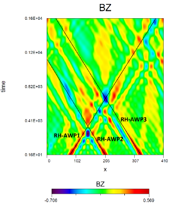
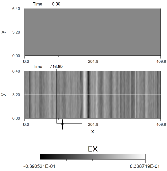
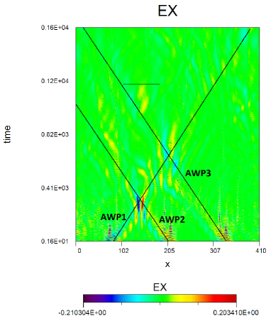
Simulations (a) shows the interaction of two Alfvén wave packets followed by the passage of a third another wave packet. The initial positions of the three wave packets are and 0.8 respectively. Their amplitudes and polarization (RH) are the same. The simulation (a) is shown in Figure 1. The left panel shows the interaction of three wave packets of the same polarization (RH) through the temporal evolution of the component . The oblique lines represent the time-distance path of the three wave packet centres (RH-AWP). In this simulation, the crossing of the two first wave packets occurs from at the position . The third packet interact with the crossing region from at the position . In fact, the third wave will interact initially with one of the initial (RH) waves before its passage through the crossing region. We can observe that the two initial and the third wave packets continue to propagate in their original direction. They are not destroyed after their interactions.
| Run | polar | init positions | Observations | |
|---|---|---|---|---|
| (a) | RH-RH RH | 0.05-0.05 0.05 | 0.2-0.5 0.8 | vortices, electron and ion beams |
| (b) | RH-RH RH | 0.1-0.1 0.1 | 0.2-0.5 0.8 | strong vortices, electron and ion beams |
| (c) | RH-LH LH | 0.05-0.05 0.05 | 0.2-0.5 0.8 | vortices, ion beams |
| (d) | RH RH-LH | 0.05 0.05-0.05 | 0.2 0.5-0.8 | vortices, ion beams |
We have to notice that because of the periodicity of the box in direction, one of the initial waves which has already interacted with the first one reappears in the right side of the box and interacts once again with the first one at leading to what we call ”artificial” interactions mainly visible at the end of simulations.
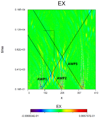
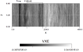
The right panel of Figure 1 shows the temporal evolution of the parallel electric field for simulation (a). A first quasi-stationary parallel electric field is observed at and it is associated to the collision between the two initial Alfvén waves according to APAWI process. While the APAWI electric field vanishes at , a weaker ones emerge mainly for from and they seem follow the propagation of the third AW. These non-APAWI electric fields are faintly visible inside AWP1-AWP2 interaction region circumscribes by the rectangle.
A second APAWI quasi-stationary parallel electric field is observed at from which is associated to the collision between the third AWP with the first initial one .
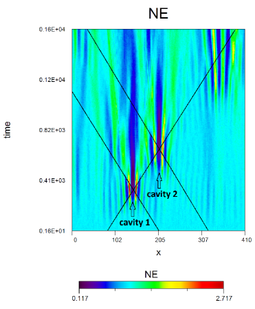
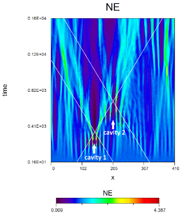
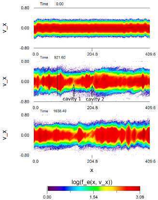
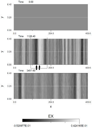
Simulations from Mottez (2012, 2015) have shown the emergence of plasma density perturbation and cavities when two Alfvén waves interact (APAWI). The left panel of Figure 2 shows the temporal evolution of the electron density for simulation (a). As observed by Mottez (2012, 2015), a large part of density modulations that emerge from waves crossing does not dissipate and persist during all our simulations. The crossing of two initial right-hand Alfvén wave packets shows a high amplitude depletion of the electron density at the locus of the interaction between the two waves at (cavity 1). A second cavity observed at results from the interaction of the third wave packet with the first one (cavity 2).
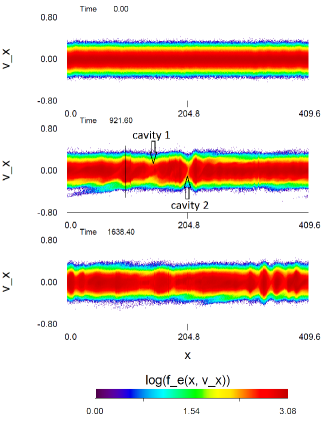
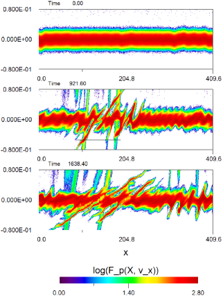
The right panel in Figure 2 shows the parallel distribution function of electrons . At , we observe electron phase space holes in form of vortices ( vortices) inside the rectangle where the AWP3 crosses the cavity 1 (from to ). The typical size of these structures is about . An electron beam of velocity emerges inside the rectangle in the distribution function near the position .
In the left panel of Figure 3, a very narrow size electric field () is observed in the snapshot at the position (see the black arrow). In the right panel of Figure 3, a more large fibril electric fields of slightly less strong strength () are observed in the snapshot at and respectively (see black arrows). The small scale electric field at is visible at the bottom of the rectangle in right panel of Figure 1, where the large size ones are faintly visible from the middle to the top of the rectangle. It is interesting to observe that the electron beam emerges between the locations of the small size electric field and the large ones.
Ion beams are also observed in the region where the third AWP crosses the cavity 1 at (Figure 4).
3.1.2 Simulation (b)
The simulation (b) is the same as the simulation (a) except that the waves amplitude is increased two times (). In the left panel of Figure 5 we observe a larger cavity depletion amplitude at both positions and . This is the consequence of large amplitude propagating waves in comparison to the simulation (a). Larger amplitude electron vortices associated to the AWP3-cavity 1 interaction region were observed in the parallel distribution function of electrons in right panel of Figure 5. This may be the direct consequence of the AW higher amplitude and instabilities which catch more particles of the core distribution and the beams (Mottez, 2001). A tiny and scattered electron beams (Velocity ) emerge from AWP3-cavity 1 crossing region ().
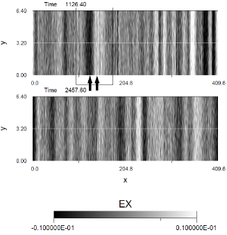
The left panel of Figure 6 shows the temporal variation of parallel electric field . We can observe a non propagative high frequency oscillations at the initial positions of the wave packets. These noises background are caused by an imperfect initialization of the wave modes. They are visible also in the right panel of Figure 1. In comparison to the simulation (a), a larger and stronger APAWI quasi-stationary electric fields are observed at crossing regions of two Alfvén waves. Another electric fields are observed at the region where the third Alfvén wave crosses the first cavity depletion from (the black rectangle region). The stronger ones are clearly visible at the top of the rectangle for . However, the last parallel electric field is more extended in space and it is not stationary as the APAWI ones.
The parallel electric fields associated to AWP3-cavity 1 crossing region are visible in the right panel of Figure 6 at the snapshot (see the black arrows). They are more stronger than those of the simulation (a) () and they show also a fibril structure.
3.2 Alfvén waves with different polarizations and initial positions
3.2.1 Simulations (c) and (d)
The simulation (c) concerns the interaction of a left-hand waves (LH) with two initial Alfvén waves of different polarization (RH-LH). The initial positions of the waves are the same as in simulation (a). The simulation (d) is for the interaction of a right-hand waves (RH) with two initial waves of different polarization (RH-LH). Unlike simulations (a),(b) and (c), the two initial wave packets in simulation (d) are initialized at and , respectively, whereas the third wave packet started at the position . In both simulations (c) and (d), we observe a weaker cavity depletion amplitude and a weaker parallel electric fields strength in comparison to the simulation (a).
3.3 Phase mixing and longitudinal density gradient
Given that, an interesting question emerges: can phase-mixing process explains the observation of the non-APAWI parallel electric fields from the passage of the third Alfvén wave packet through cavity 1 region (density inhomogeneity gradients)?
Phase-mixing has been associated to density depletion or cavity (plasma under-density) in the auroral regions (Génot et al., 1999, 2000; Mottez & Génot, 2011) or more recently in interplume regions (Daiffallah & Mottez, 2017). This mechanism has been associated also to density bump or plasma over-density in the solar coronal loops (Tsiklauri, 2007, 2011, 2012, 2016) or in a solar coronal hole (Wu & Fang, 2003).
However, APAWI density gradients show a longitudinal modulation like profile for all our simulations (see the left panel of Figure 7). The parallel electric fields observed for the simulations (a) and (b) in Figure 3 and the right panel of Figure 6, respectively show similar longitudinal profile.
Phase-mixing process in the case of longitudinal gradient of density is more complex. In the context of resonant mode conversion and using analytic calculations, Xiang, Chen & Wu (2019) showed that kinetic Alfvén wave is hardly excited when , where is the angle between the background parallel magnetic field and the density gradient of the plasma. Génot et al. (1999) demonstrated analytically that a pure parallel electric field is generated in the regions of transverse density gradients, whereas in the regions of longitudinal density gradients, the emerged parallel and perpendicular electric field are coupled. Lysak & Song (2008) have performed simulations where they considered the case of parallel and perpendicular density gradients in the Earth magnetosphere. They observed that a parallel electric field was developed at the gradient regions in the Alfvén speed.
In addition to theoretical possibilities that are cited above, we suggest for our simulation that the passage of the Alfvén waves can induce a relative drift along the discontinuity boundary between the background plasma and the longitudinal APAWI density cavity structure. This will generate an interface waves along the discontinuity which allows the incoming wave to interact with a wavy density gradient (oblique gradient). These wavy fiber-structures can be seen in the left panel of Figure 7 for the simulation (b). When the wave reaches the oblique density cavity, the distorted wave front develops small-scale structures in the transverse -direction. Since we are in inertial regime, when reaches the electron inertial length , a parallel electric field is generated at this transverse gradient by phase-mixing process.
The electrons and ions drift are at the same velocity . Furthermore, the transverse size of our box is large in comparison to the ion gyroradius . This gives an MHD behavior to the plasma in the transverse direction (Faganello & Califano, 2017).
In our simulations, interface waves can be generated when the third wave packet cross the region of longitudinal density (cavity 1) that emerged from APAWI process. Two drift terms can contribute to the creation of small-scale structures () in the transverse direction : the first one is , where is the electric field perturbation of the third AW in the -direction. The second term is , where is the magnetic field perturbation of the third AW in the -direction, and is the parallel electric field that results from the collision between the two initial Alfvén waves (APAWI). This last term which depends on the lifetime of vanish rapidly in comparison to the first term. To compare between the contribution of these two terms we have calculated the ratio of the magnitude of the first term to the magnitude of the second term:
| (4) |
where , is the phase velocity of the incoming third Alfvén wave, or and . In Mottez (2015), the simulation AWC009 is quasi similar to the APAWI part (RH-RH) of the simulation (a) where the maximum of APAWI parallel electric field is about 0.013. In simulation (a), the phase velocitie of the third Alfvén wave packet varies from 0.0855 to 0.2029. Then the ratio in equation 4 for the simulation (a) is between 5.26 and 12.49. This means that in simulation (a), the first drift term is almost predominant in comparison to the second one.
It is possible that interface waves are generated along the longitudinal APAWI density structures earlier when the two initial waves (RH-RH) (or RH-LH) move away after their interaction. Thus, outgoing wave packets will cross a part of the emerged APAWI density generating primordial small-scale structures in the transverse direction before the passage of the third wave packet. Given that, it is interesting to calculate the ratio of the velocity drift magnitude () of a single (RH) Alfvén wave to the velocity drift magnitude of a single (LH) wave. This ratio is about 1.16 () and 7.13 () for waves of the same amplitude, which means that the single (RH) Alfvén wave will induce a more important transversal modulations in the APAWI longitudinal density structures than the single (LH) wave of the same amplitude. This result is in favor of stronger parallel electric field generation in simulations (a) and (b).
In the phase-mixing process, higher incoming wave amplitude can induce more concentration of space charge on the transverse density gradient regions, as well as the creation of a stronger parallel electric fields, which in turn accelerate electrons more efficiently (see Génot et al., 1999; Tsiklauri & Haruki, 2008). This is the case of simulation (b) where the amplitude of the third incoming AW is larger compared to that of the other simulations.
For both simulation (a) and (b), the phase-mixed parallel electric fields associated to longitudinal density gradients shows clearly a wavy fiber-like structures ( for ). In general, these tiny localized structures are difficult to observe, particularly for snapshots where a poor contrast shows mainly the global longitudinal modulation. They are better discernible in simulation (b) for the electron parallel velocity (right panel of Figure 7) at . Different patterns of these structures can be seen depending on the size of the gradient and the wavelength of the perturbation along the transverse direction .
In simulation (a), the horizontal length of the small-scale parallel electric associated to phase-mixing process measured from the left panel of Figure 3 () is about . In simulation (b), the parallel electric field associated to the acceleration region is rather formed by a cluster of small-scale fiber structures (right panel of Figure 6 at ), where the the horizontal length of a single fiber is about . These sizes fit very well the size of the the electron inertial length ().
In conclusion, when the AWP cross the longitudinal APAWI density gradient structure, fiber structures start to oscillate in the transverse direction. Parallel electric fields are generated in each small-structures by phase mixing process as long as the size of the fiber-transverse-section crossed by the wave front is in range of . Then, the large size parallel electric fields associated to the modulations of density is the contribution of all fine-structure parallel electric fields.
4 Discussion and conclusion
APAWI process causes a significant modulation of the plasma density and accelerate particles in the parallel direction. This process have been studied for higher and lower ambient magnetic field by Mottez (2012, 2015), respectively. In the present work we are trying to generalize the APAWI process by interacting a third parallel Alfvén wave packet with the two initial ones. The aim was to explain the observation of high-energy electrons through nonlinear wave-wave interaction model.
We have investigated the nonlinear interaction of three crossed parallel Alfvén wave packets in initially uniform plasma (), by using a particle in cells (PIC) numerical simulation code. The two closest Alfvén waves will collide first in the context of APAWI process giving rise to an inhomogeneous plasma at the APAWI crossing region. Then the third Alfvén wave interact in turn with the emerged density modulations and waves. We observe parallel electric fields and ion beams localized at the APAWI crossing region. We suggest that they result from phase-mixing process between the third Alfvén waves and the APAWI density depletion. This is the case for waves with different polarizations like (RH-LH LH) or (RH RH-LH) configuration, where (RH) and (LH) mean the right and the left circular polarization respectively. However, electron beams () associated to larger parallel electric fields are observed for the interaction (RH-RH RH), particularly when large amplitude propagating Alfvén waves are simulated.
While APAWI density structures show a longitudinal gradients, we explain the transversal modulations to the propagation of interface waves generated mainly by the velocity drift along the boundaries of the emerged longitudinal APAWI density structures, where is the background magnetic field, and is the electric field perturbation of the crossing waves. Our simulations were performed in the inertial regime. Therefore, the transverse size of the small-scale density gradients have to be of order of to produce a strong parallel electric field that can accelerate electrons in the direction of the background magnetic field. We have estimated from simulation (b) that the longitudinal size of the large phase-mixed parallel electric field structure is of order of 6 km in the auroral zone, where the transverse scale length (fine structures) m. The possibility and the observation of electric field structures of comparable size have been discussed in Karlsson et al. (2020). Nevertheless, large amplitude interface waves can evolve to Kelvin Helmholtz instability. In this context, many authors have reported the important role that plays this instability in the Earth magnetosphere dynamics (see Faganello & Califano, 2017, and references therein). Structures and even vortices from this instability have been also observed in the auroral sheet (Hallinan and Davis, 1970).
Actually, the process of interaction of three parallel waves invoked in this study is different from the APAWI one. APAWI process involve simultaneous crossing of parallel counter-propagating Alfvén waves, whereas in the mechanism studied here, the third wave packet arrives with a very short delay compared to the instant when the two initial waves interact. From a geometrical point of view, the two process are comparable since wave packets propagate in the parallel direction to the background magnetic field. Nevertheless, to compare between the two process from physical point of view, the three propagating Alfvén waves have to cross together simultaneously. This can be possible only if the third wave packet propagates obliquely (or three oblique Alfvén waves). However, this involves a further from the oblique propagation in addition to generated from non-linear coupling of the counter-propagating Alfvén waves, which changes a bit the problem. This may be the subject of further study.
It is interesting to notice that because of the periodic horizontal boundary conditions, the complex interaction that happens at the final stage of simulations can give us an idea about phenomena related to multiple reflection of Alfvén waves in a resonant cavity. However, how to justify the presence of waves of different polarization in our simulations since basically we want to study the self-interaction of a single Alfvén wave packet when it undergoes multiple reflection? To answer to this question, we can imagine a situation where a (RH) Alfvén wave packet propagates in () plasma as in our simulation but surrounding by a plasma with (). Using a kinetic approach, Buti et al. (2000) have shown that (RH) Alfvén wave packet is unstable for plasma with and can collapse when it arrives at a turning point depending on the initial amplitude of the wave packet. At this critical point, the (RH) wave packet would change polarization to become like a (LH) wave packet. Given that, this transformed (LH) wave packet can return back from a reflective boundary layer or from strong conditions turning point and cross the initial (RH) wave packet. If this interaction (RH-LH) can occur, then three wave packets (or more) of different polarizations (and amplitudes) can interact also under the same circumstances. The mechanism of conversion from fast magneto-acoustic wave to Alfvén and slow wave above an active region () in low solar corona, including a change in polarizations and amplitudes, offers also a possibility to a single wave to collide with their counter-propagating parts after reflections and damping in regions of rapidly Alfvén speed increases in open magnetic field (Khomenko and Cally, 2012), or in closed magnetic field configuration like coronal magnetic loop (Fletcher and Hudson, 2008). Obviously, the wavelengths of the MHD waves and the size of the resonant cavity have to be in the range where kinetic effects of the plasma can take place.
Alfvén waves propagating through a longitudinal density gradient can undergo a reflection since it propagation velocity changes along the parallel direction. Musielak et al. (1992) have calculated the critical frequency under which incident Alfvén wave can be reflected by a longitudinal gradient. In term of our dimensionless variables, this frequency can be written as , where the prime in this equation indicates the spatial () derivative, and is the Alfvén velocity at the background uniform plasma . The Alfvén velocity for a single wave is calculated along a typical APAWI cavity which we approximate with a longitudinal Gaussian density profile. We assume that the maximum amplitude of a typical moderate cavity and it width are: , , respectively. We have find that . From initial conditions, the frequencies in the (LH) wave packet varies from () to (), and the frequencies in the (RH) wave packet varies from () to (), where is the wave number. Therefore, it is clear that a small part () of the wave packet will undergo a reflection from APAWI longitudinal density cavities. However, the equation for in Musielak et al. (1992) is valid only for linear Alfvén waves of relatively low amplitude and for non-fibril cavity. Furthermore, Alfvén wave packet modulates in time the density gradient making it profile time-dependent, which makes the calculation of the dynamical more complicated.
In addition to the non-linear phase mixing process, it is possible that the reflection of the wave packets from the emerged longitudinal APAWI density gradients contributes to electron heating, it depends on the transmitted wave amplitude (Bose et al., 2019). It is possible also that a part of the parallel Alfvén wave can be trapped between two reflective longitudinal APAWI gradients if it wavelength is smaller than the distance between these two gradients. At the MHD scale, Moore et al. (1991) have shown that the heating of coronal holes is predominantly caused by the reflection and the dissipation of the trapped Alfvén waves rather than of the transmitted waves. By invoking turbulence cascade, similar mechanism could possibly occurs at the kinetic level. However, it is difficult to confirm these possibilities from our simulations since we observe the contribution of three propagating Alfvén waves. In this regard it will be important to carry out simulations of a single parallel Alfvén wave propagation through longitudinal (fibril) density gradients of different sizes. These will be the topics of a forthcoming investigation.
Acknowledgements
I would like to express my sincere gratitude to Fabrice Mottez from Observatoire de Paris for the original idea of the paper, and for years of discussion, inspiration and help. I am also thankful to the anonymous referee for constructive comments and suggestions that improved greatly the quality of the paper.
Declaration of Interests
The authors report no conflict of interest.
Data availability
The data that support the findings of this study are available within the article.
References
- Bian & Kontar (2011) Bian, N. H., & Kontar, E. P. 2011 Parallel electric field amplification by phase mixing of Alfven waves. Astron. Astrophys. 527, A130.
- Bose et al. (2019) Bose, S., Carter, T., Hahn, M., Tripathi, S., et al. 2019 Measured Reduction in Alfvén Wave Energy Propagating through Longitudinal Gradients Scaled to Match Solar Coronal Holes. Astrophys. J. 882(2), 183.
- Buti et al. (2000) Buti, B., Velli, M., Liewer, P. C., Goldstein, B. E., & Hada, T. 2000 Hybrid simulations of collapse of Alfvénic wave packets. Phys. Plasmas. 7(10), 3998–4003.
- Daiffallah & Mottez (2017) Daiffallah, K., & Mottez, F. 2017 Electron acceleration and small-scale coherent structure formation by an Alfvén wave propagating in coronal interplume region. Astron. Nachr. 338(7), 781–789.
- Faganello & Califano (2017) Faganello, M., & Califano, F. 2017 Magnetized Kelvin-Helmholtz instability: theory and simulations in the Earth’s magnetosphere context. J. Plasma Phys. 83(6), 535830601.
- Fletcher and Hudson (2008) Fletcher, L., and Hudson, H.S. 2008 Impulsive Phase Flare Energy Transport by Large-Scale Alfvén Waves and the Electron Acceleration Problem. Astrophys. J. 675(2), 1645.
- Génot et al. (1999) Génot, V., Louarn, P., & Le Quéau, D. 1999 A study of the propagation of Alfvén waves in the auroral density cavities. J. Geophys. Res. 104(A10), 22649.
- Génot et al. (2000) Génot, V., Louarn, P., & Mottez, F. 2000 Electron acceleration by Alfvén waves in density cavities. J. Geophys. Res. 105(A12), 27611.
- Génot et al. (2004) Génot, V., Louarn, P., & Mottez, F. 2004 Alfv´en wave interaction with inhomogeneous plasmas: acceleration and energy cascade towards small-scales. Ann. Geophys. 22(6), 2081.
- Goertz (1985) Goertz, C. K. 1985 Auroral arc formation: kinetic and MHD effects. Space Sci. Rev. 42(3–4), 499.
- Hallinan and Davis (1970) Hallinan, T. J., Davis, T. N. 1970 Small-scale auroral arc distortions. Planet. Space Sci. 18(12), 1735–1737.
- Heyvaerts & Priest (1983) Heyvaerts, J., & Priest, E. R. 1983 Coronal heating by phase-mixed shear Alfven waves. Astron. Astrophys. 117, 220–234.
- Howes & Nielson (2013) Howes, G. G., & Nielson, K. D. 2013 Alfvén wave collisions, the fundamental building block of plasma turbulence. I. Asymptotic solution. Phys. Plasmas. 20(7), 072302.
- Howes et al. (2018) Howes, G. G., McCubbin, A. J., & Klein, K. G. 2018 Spatially localized particle energization by Landau damping in current sheets produced by strong Alfvén wave collisions. J. Plasma Phys. 84(1), 905840105.
- Karlsson et al. (2020) Karlsson, T., Andersson, L., Gillies, D. M., et al. 2020 Quiet, Discrete Auroral Arcs–Observations. Space Sci. Rev. 216(1), 16.
- Khomenko and Cally (2012) Khomenko, E., & Cally, P.S. 2012 Numerical Simulations of Conversion to Alfvén Waves in Sunspots. Astrophys. J. 746(1), 68.
- Lysak & Song (2008) Lysak, R. L., & Song, Y. 2008 Propagation of kinetic Alfvén waves in the ionospheric Alfvén resonator in the presence of density cavities. Geophys. Res. Lett. 35(20), L20101.
- Moore et al. (1991) Moore, R. L., Musielak, Z. E., Suess, S. T., et al. 1991 Alfvén Wave Trapping, Network Microflaring, and Heating in Solar Coronal Holes. Astrophys. J. 378, 347.
- Mottez (2001) Mottez, F. 2001 Instabilities and Formation of Coherent Structures. Astrophys. Space Sci. 277, 59.
- Mottez (2008) Mottez, F. 2008 A guiding centre direct implicit scheme for magnetized plasma simulations. J. Comput. Phys. 227(6), 3260.
- Mottez (2015) Mottez, F. 2015 Plasma acceleration by the interaction of parallel propagating Alfvén waves. J. Plasma Phys. 81(1), 325810104.
- Mottez (2012) Mottez, F. 2012 Non-propagating electric and density structures formed through non-linear interaction of Alfvén waves. Ann. Geophys. 30(1), 81–95.
- Mottez & Génot (2011) Mottez, F., & Génot, V. 2011 Electron acceleration by an Alfvénic pulse propagating in an auroral plasma cavity. J. Geophys. Res.: Space Phys. 116, A00K15.
- Mottez et al. (1998) Mottez, F., Adam, J. C., & Heron, A. 1998 A new guiding centre PIC scheme for electromagnetic highly magnetized plasma simulation. Comput. Phys. Commun. 113(2–3), 109.
- Musielak et al. (1992) Musielak, Z. E., Fontenla, J. M., & Moore, R. L. 1992 Klein-Gordon equation and reflection of Alfvén waves in nonuniform media. Phys. Fluids B 4(1), 13.
- Nielson et al. (2013) Nielson, K. D., Howes, G. G., & Dorland, W. 2013 Alfvén wave collisions, the fundamental building block of plasma turbulence. II. Numerical solution. Phys. Plasmas. 20(7), 072303.
- Pezzi et al. (2017) Pezzi, O., Parashar, T. N., Servidio, S., et al. 2017 Colliding Alfvénic wave packets in magnetohydrodynamics, Hall and kinetic simulations. J. Plasma Phys. 83(1), 705830108.
- Tsiklauri (2007) Tsiklauri, D. 2007 A minimal model of parallel electric field generation in a transversely inhomogeneous plasma. New J. Phys. 9(8), 262.
- Tsiklauri & Haruki (2008) Tsiklauri, D., & Haruki, T. 2008 Physics of collisionless phase mixing. Phys. Plasmas 15(11), 112902.
- Tsiklauri (2011) Tsiklauri, D. 2011 Particle acceleration by circularly and elliptically polarised dispersive Alfven waves in a transversely inhomogeneous plasma in the inertial and kinetic regimes. Phys. Plasmas 18(9), 092903.
- Tsiklauri (2012) Tsiklauri, D. 2012 Three dimensional particle-in-cell simulation of particle acceleration by circularly polarised inertial Alfven waves in a transversely inhomogeneous plasma. Phys. Plasmas 19(8), 082903.
- Tsiklauri (2016) Tsiklauri, D. 2016 Collisionless, phase-mixed, dispersive, Gaussian Alfven pulse in transversely inhomogeneous plasma. Phys. Plasmas 23(12), 122906.
- Verniero & Howes (2018) Verniero, J. L., & Howes, G. G. 2018 The Alfvénic nature of energy transfer mediation in localized, strongly nonlinear Alfvén wavepacket collisions. J. Plasma Phys. 84(1), 905840109.
- Wu & Fang (2003) Wu, D. J., & Fang, C. 2003 Coronal Plume Heating and Kinetic Dissipation of Kinetic Alfvén Waves. Astrophys. J. 596(1), 656–662.
- Xiang, Chen & Wu (2019) Xiang, L., Chen, L., Wu, D. J. 2019 Resonant Mode Conversion of Alfvén Waves to Kinetic Alfvén Waves in an Inhomogeneous Plasma. Astrophys. J. 881(1), 61.
- Zhao et al. (2011) Zhao, J. S., Wu, D. J., & Lu, J. Y. 2011 A nonlocal wave-wave interaction among Alfvén waves in an intermediate- plasma. Phys. Plasmas 18(3), 032903.