- IRS
- Intelligent reflecting surface
- RIS
- reconfigurable intelligent surface
- irs
- intelligent reflecting surface
- PARAFAC
- parallel factor
- TALS
- trilinear alternating least squares
- BALS
- bilinear alternating least squares
- DF
- decode-and-forward
- AF
- amplify-and-forward
- CE
- channel estimation
- RF
- radio-frequency
- THz
- Terahertz communication
- EVD
- eigenvalue decomposition
- CRB
- Cramér-Rao lower bound
- CSI
- channel state information
- BS
- base station
- MIMO
- multiple-input multiple-output
- NMSE
- normalized mean squared error
- 2G
- Second Generation
- 3G
- 3 Generation
- 3GPP
- 3 Generation Partnership Project
- 4G
- 4 Generation
- 5G
- 5 Generation
- 6G
- 6 generation
- E-TALS
- enhanced TALS
- UT
- user terminal
- UTs
- users terminal
- LS
- least squares
- KRF
- Khatri-Rao factorization
- KF
- Kronecker factorization
- MU-MIMO
- multi-user multiple-input multiple-output
- MU-MISO
- multi-user multiple-input single-output
- MU
- multi-user
- SER
- symbol error rate
- SNR
- signal-to-noise ratio
- SVD
- singular value decomposition
Channel Estimation for Intelligent Reflecting Surface Based MIMO Communication Systems via Tensor Modeling
Channel Estimation for Intelligent Reflecting Surface Based MIMO Communication Systems: A Tensor Modeling Approach
Tensor Modeling Approach to Receiver Design for Intelligent Reflecting Surface Assisted MIMO Systems
A Tensor Approach to Intelligent Reflecting Surface Assisted MIMO Systems: Semi-Blind Joint Channel and Symbol Estimation
Semi-Blind Joint Channel and Symbol Estimation in IRS-Assisted MIMO Systems
Semi-Blind Joint Channel and Symbol Estimation in Intelligent Surface Assisted MIMO Systems
Semi-Blind Joint Channel and Symbol Estimation in IRS-Assisted Multi-User MIMO Networks
Abstract
Intelligent reflecting surface (IRS) is a promising technology for beyond 5 Generation of the wireless communications. In fully passive IRS-assisted systems, channel estimation is challenging and should be carried out only at the base station or at the terminals since the elements of the IRS are incapable of processing signals. In this letter, we formulate a tensor-based semi-blind receiver that solves the joint channel and symbol estimation problem in an IRS-assisted multi-user multiple-input multiple-output system. The proposed approach relies on a generalized PARATUCK tensor model of the signals reflected by the IRS, based on a two-stage closed-form semi-blind receiver using Khatri-Rao and Kronecker factorizations. Simulation results demonstrate the superior performance of the proposed semi-blind receiver, in terms of the normalized mean squared error and symbol error rate, as well as a lower computational complexity, compared to recently proposed parallel factor analysis-based receivers.
Index Terms:
Channel estimation, intelligent reflecting surface, MIMO system, PARATUCK decomposition.I Introduction
Intelligent reflecting surface is a promising technology to beyond 5 Generation (5G) of the wireless networks, which may offer high spectral efficiency, while improving the energy efficiency/reliability and reducing the end-to-end latency and cost [1]. An IRS is a two-dimensional array structure composed of a large number of passive (or semi-passive) software-controlled reconfigurable scattering elements, whose electromagnetic response can be dynamically adjusted [2]. In most studied implementations, an IRS operates by applying phase shifts to the incident radio waves in favor of signal reception.
In an IRS-assisted wireless network, the acquisition of instantaneous channel state information (CSI) is an important and challenging task, since the accuracy of the CSI has significant impact on the optimization of the IRS phase shifts. Recent works have proposed different solutions to tackle the channel estimation (CE) problem in IRS-assisted communications in single-user single-antenna/multi-antenna systems [3, 4]. In [3], the CE performance is evaluated by means of a tensor modeling of the received signal using an iterative solution, which increases the complexity. In [4], the authors assume a semi-active IRS structure. This assumption undermines the low-cost structure of the IRS, since radio-frequency (RF) chains are used. Considering a multi-user (MU) scenario, [5] and [6] exploit IRS element grouping and spatial correlation to control the pilot overhead. In both [5] and [6], the authors assume a quasi-static block fading channel model for all the involved links, which leads to a degradation on the performance of CE when some mobility of the user terminal (UT) is considered. In particular, [6] exploits the correlation among the UT-IRS- base station (BS) channels of different users. Note that all these methods are pilot-assisted schemes. In contrast, blind and semi-blind receivers perform CE and data detection without employing pilot sequences.
Approaches based on tensor modeling have been proposed for conventional point-to-point multiple-input multiple-output (MIMO) systems (see, e.g., [7, 8] and the references therein). Specifically, a constrained factor decomposition is derived in [7] to formulate a space-time spreading model, while [8] capitalizes on the PARATUCK111The name PARATUCK is derived from the combination of the PARAFAC and Tucker tensor decompositions. model to derive a semi-blind joint CE and data detection for multi-carrier MIMO systems. In the context of IRS-assisted communications, tensor modeling has been recently proposed in [9] to solve the CE problem in a multi-user multiple-input single-output (MU-MISO) IRS-assisted system, by capitalizing on the multidimensional structure of the signal reflected by the IRS via a pilot-assisted scheme based on the parallel factor (PARAFAC) tensor decomposition. Reference [3] goes in the same direction, by proposing iterative and closed-form CE methods for single-user MIMO IRS-assisted communications. These works, however, can only operate with the use of pilot sequences, at the cost of increasing the end-to-end latency.
This letter222Notation: Scalars are denoted by lowercase letters (), vectors by bold lowercase letters (, matrices by bold capital letters (, and tensors by calligraphic letters . The transpose and Hermitian transpose of a given matrix are denoted by and , respectively. is a diagonal matrix holding the -th row of on its main diagonal. is the Frobenius norm of a matrix. The operator forms a diagonal matrix out of its vector argument, while and denote the Khatri Rao and Kronecker products, respectively. The operator vectorizes an matrix argument, while does the opposite operation. denotes the -th row of the matrix , and is an identity matrix of size . formulates a semi-blind receiver that solves the problem of joint channel and symbol estimation in an IRS-assisted wireless network without the need of a dedicated training stage. We address a realistic scenario, in which the channels between the UT and the IRS undergo shorter term variations compared to the channel between the BS and the IRS. Considering an uplink multi-user multiple-input multiple-output (MU-MIMO) setup, we show that the signals reflected by the IRS and received at the BS follow a generalized PARATUCK tensor model. By exploiting the algebraic structure of this tensor model, we derive a semi-blind receiver algorithm that allows the BS to jointly estimate the multiple uplink UT-IRS channels, the common IRS-BS channel, and the data symbols transmitted by all UTs, in a closed-form way by solving simple rank-one matrix approximation problems.
The proposed two-stage closed-form semi-blind receiver consists of a sequential combination of the Khatri-Rao factorization (KRF) and Kronecker factorization (KF) schemes, and is referred to as KAKF in the sequel. We compare our proposed semi-blind method with a recently proposed PARAFAC-based receiver [9] and with the KRF receiver [3], which are two pilot-assisted methods. The first is an iterative solution that solves two least squares (LS) problems to estimate the involved channel matrices, while the second is a closed-form scheme based on rank-one matrix approximations. Numerical results corroborate the improved CE accuracy, superior symbol error rate (SER) performance, and lower computational complexity offered by the proposed semi-blind receiver.
II System Model
Consider the uplink communication in an IRS-assisted MU-MIMO system, in which the BS is equipped with antennas, the IRS is composed of passive scattering elements, while each of the UTs has antennas333We assume that the users have the same number of antennas for simplicity of exposition. However, the proposed solution can be straightforwardly adapted to users with different numbers of antennas.. We assume that the BS and the IRS are deployed at fixed heights, e.g., on the roof of a building, compared to the moving UTs. In this sense, we assume that the transmitted data is organized into data frames. Each frame is composed of symbol periods, where denotes the number of blocks contained in each frame and is the number of time slots in each block. This transmission structure is illustrated in Fig. 1.
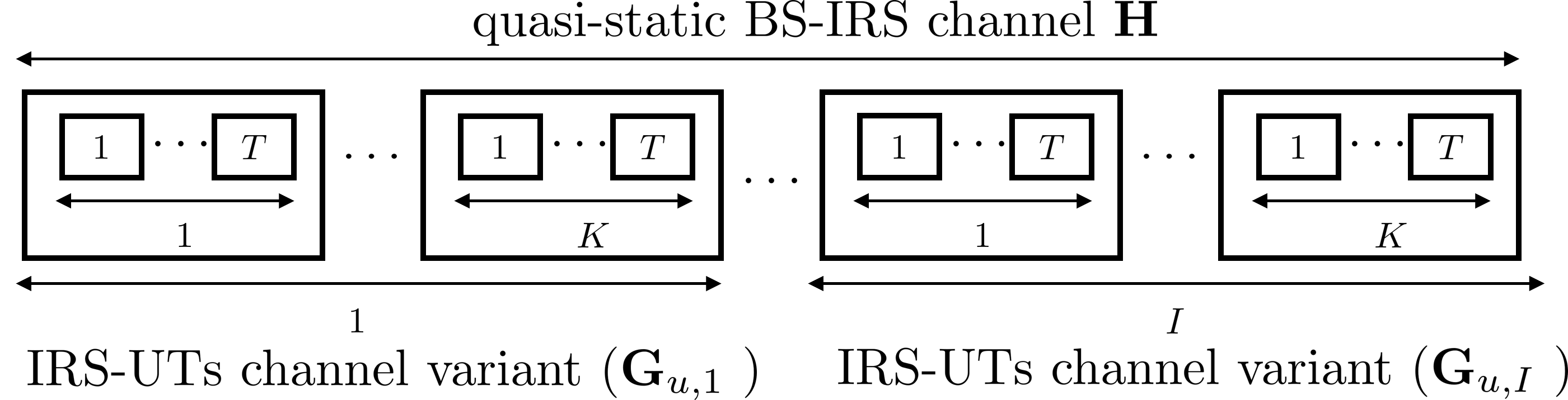
To capture a certain level of UT mobility, we assume that the UT-IRS channels stay constant during a frame, but vary in different frames independently. On the other hand, the IRS-BS channel follows a quasi-static model [10], and is assumed to remain constant during the transmission time. This is a reasonable assumption since the BS and the IRS are assumed to be deployed at fixed positions. We also assume that the direct communication links between the UTs and the BS are weak or not available. Each UT sends data symbol vector that are diagonally coded as , where is the symbol vector transmitted by the -th UT at the -th time slot, , whose entries are drawn from any finite-alphabet constellation. The vector denotes the coding vector associated with the -th UT at the -th block. The quasi-static IRS-BS channel matrix is denoted by , while the time-varying channel matrix between the IRS and the -th UT at frame is denoted as . Therefore, the received signal at the BS coming from the -th UT via IRS is given by
| (1) |
where collects the phase shifts applied by the IRS during the -th block, and denotes the additive white Gaussian noise (AWGN) term. Note that the IRS phase shifts configuration and the coding vectors are known by the BS and remains constant during the time slots within the -th block, but varies between different blocks.
At the BS, the received signal is represented as the superposition of the signals coming from the UTs. Therefore, the total received signal can be expressed as
| (2) |
or, more compactly,
| (3) |
where represents the augmented multi-user uplink channel matrix at frame . Also, collects the transmitted data symbol vectors from all UTs, and collects the coding vectors used by the UTs in block . Defining that collects the received signal vectors during the time slots, we obtain
| (4) |
where is the phase shifts matrix, and . The useful part of the received signal in (4) can be identified as a generalized PARATUCK decomposition of a fourth-order tensor written in terms of its -th matrix slices, where the frame and block dimensions are fixed. Our goal is to jointly estimate in a semi-blind way, i.e., without resorting to a dedicated training stage, the IRS-BS channel , the UTs-IRS channels that make up and the transmitted data symbols from the received signal tensor in (4). To this end, in the following, we formulate the detailed processing stages of the proposed closed-form semi-blind receiver.
III Proposed Semi-Blind KAKF Receiver
The vectorized form of the received signal in (4) as
| (5) |
where , and we have used the Kronecker product property vecvec. Defining that collects the received signals for the -th block, we can rewrite (5) as
| (6) |
where and , with . Resorting again to the property of the Kronecker product, we rewrite (6) more compactly as
| (7) |
Finally, by collecting the received signals , , over the blocks, we have
| (8) |
where From (8), we observe that the LS estimate of the Khatri-Rao product can be obtained. To avoid the pseudo inverse calculation, we assume that is constructed based on a Discrete Fourier Transform factorization design444The design of the phase shifts and the coding matrices is a relevant point, especially in the optimization context. However, the optimization study on these matrices is out of the scope of this work. Further, the structure of and impacts the design of the matrix regarding complexity aspects. as in [11], such that . Note, however, that the orthogonality of is not requirement of our semi-blind receiver. Using estimated from , the individual estimates of (i.e., UTs-IRS channels) and can be obtained by means of the KRF approach, which consists of solving a set of rank-one matrix approximation problems. Sequentially, from , which is estimated via KRF in the previous stage, the individual estimates of and can be obtained using the KF, which consists of solving a single rank-one matrix approximation problem. The KAKF receiver accomplishes joint channel and symbol estimation in closed-form from two stages as detailed in the following.
III-A Khatri-Rao Factorization (KRF) Stage
Considering the noisy version of (8), and exploiting the knowledge of the phase shifts and coding matrices and , respectively (and thus ), the BS firstly applies a linear filtering with , yielding
| (9) |
where represents the equivalent filtered noise term. From (9), the individual estimates of and can be obtained from their noisy Khatri-Rao product by solving
| (10) |
Defining as the -th column of , we have , where is the corresponding column of the noise matrix in (9), and and corresponds to the -th column of the matrices and , respectively. Using the property , Problem (10) can be equivalently recast as
| (11) |
where . Note that can be approximated as a rank-one matrix given by the outer product of and . The solution of (11) is given by the best rank-one approximation obtained from the dominant left and right singular vectors of [12]. Therefore, the KRF stage of the proposed receiver thus consists of solving independent rank one-approximation problems, as summarized in Algorithm 1.
III-B Kronecker Factorization Stage
Recall that the estimate of is delivered from the KRF stage in section III-A. From (5) and (6), we have that can be approximated as the Kronecker product of the transmitted data matrix and IRS-BS channel matrix, i.e.
| (12) |
According to the Kronecker product definition, can be seen as the following block matrix
| (13) |
where each of the sub-matrices represents a scaled version of , i.e.,
| (14) |
for and . Therefore, the individual estimates for and can be obtained from by solving
| (15) |
The matrix can be properly rearranged by stacking the vectorized form of the blocks in (14), as in [13], so that a rank-one matrix is constructed, as follows
| (16) |
Therefore, the problem in (15) becomes equivalent to solving the following rank-one matrix approximation problem
| (17) |
where and . The best estimates to and (and consequently to and ) are obtained by truncating the singular value decomposition (SVD) of to its rank-one approximation. Therefore, the KF stage of the proposed receiver is solved from a single rank-one matrix approximation step, as shown in Algorithm 2.
-
1.
Construct the rank-one matrix from .
-
2.
Reconstruct and by unvec and 4. Remove the scaling ambiguities of and . end
III-C Identifiability Analysis and Computational Complexity
The necessary condition on the identifiability of the proposed KAKF receiver is linked to the linear filtering step in (9). It requires that the designed matrix to be full row-rank, implying that . This condition establishes a lower-bound on the number of transmission blocks necessary for the proposed receiver to jointly estimate the channels and data symbols of all the users. This indicates that the required number of transmission blocks scales with , and at least linearly, as . Note that the computational complexity in both stages (Algorithms 1 and 2) of the proposed KAKF receiver is dominated by the truncated SVD. This truncated SVD can be efficiently obtained from partial QR factorization schemes [14]. The total complexity of KAKF receiver is given by , since the KF stage involves a single rank- approximation step, while the KRF one has rank- approximation steps. It is worth noting that in the KRF stage the factors of the Khatri-Rao product can be estimated independently. Hence, the processing delay can be controlled by executing the estimation steps in parallel processors at the BS. The pilot-assisted method [9], used as benchmark, is an iterative solution where the computational complexity is dominated by the pseudo-inverse calculation such that the total complexity is .
III-D Scaling Ambiguities
Once the rank-one approximations are computed via truncated SVDs, the estimates provided by the KRF and KF stages are unique up to scaling ambiguities. From the KRF stage, the following estimates are obtained and , where and are diagonal matrices that contain the column scaling ambiguities such that To remove these scaling ambiguities, the BS needs to know one row of or . Such a scaling can be handled by assuming that the first row of is known. This is equivalent to assuming that the BS has the knowledge of the first row of and the first row of the BS-IRS channel . In practice, the BS can estimate the first row of based on a simple scheme proposed in [10], where the IRS reflects back pilots sent by the BS.
IV Simulation Results
In this section, the performance of the proposed two-stage KAKF semi-blind receiver is evaluated in terms of the normalized mean squared error (NMSE) of the estimated channels, average SER, and average runtime metrics. Particularly, the NMSE of the BS-IRS CE is defined as , where = or , and represents the estimation of the channel at the -th Monte Carlo run. The results are averaged over independent Monte Carlo runs. We assume that the involved channels follow geometric models such that and (for each UT), in which the number of dominant paths in the IRS-BS and UTs-IRS links are denoted by and 555For simplicity, in the simulations, we assume that each UT contributes with the same number of dominant paths., respectively, while and denote the channel gain vectors. The departure and arrival angles are randomly and uniformly distributed between and , while the path gains follow a complex Gaussian distribution with zero mean and unitary variance. The transmitted data symbols are chosen from a -PSK alphabet, and each UT has a transmission rate of for a given coherence time and data transmission time .
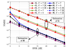
Figure 2a depicts the NMSE performance of the proposed semi-blind KAKF receiver as a function of the signal-to-noise ratio (SNR). As a performance benchmark, we also depict the results of the bilinear alternating least squares (BALS) method proposed in [9], as well as the results of the closed-form KRF solution proposed in [3], which are pilot-assisted methods. Although the competitive methods do not consider UTs-IRS time-varying channels, we adapt them to the time-varying case to ensure a fair comparison. In this experiment, we assume , , , each UT equipped with antennas (). Besides, we consider and . Further, the BS captures UTs-IRS channel variations and . As it can be observed, our proposed semi-blind KAKF receiver significantly outperforms the BALS method in the accuracy of the estimation of the UTs-IRS channel . As for the IRS-BS channel , the BALS method outperforms the proposed receiver in the low signal-to-noise ratio (SNR) regime for . However, in the medium-to-high SNR regime, the two receivers show similar performances. Besides, the BALS estimator, which requires pilot sequences, has a very modest gain for . This is an expected result since the IRS-BS channel is estimated in the second KF stage when using the KAKF receiver. Therefore, it is affected by the error propagation originating from the first KRF stage. This explains its worse performance in estimating in the low SNR regime compared to BALS, in which each channel matrix is estimated in an alternating way, thus avoiding error propagation. Note that the KRF [3] performance is similar to the BALS performance. However, considering the end-to-end channel, our proposed scheme offers a remarkable improvement in the CE accuracy. For an SNR equal to 20 dB, while KAKF and BALS have similar NMSE performances for the estimation of , the proposed scheme offers an order of magnitude improvement in the estimation of (see Fig. 2a).
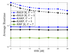
To evaluate the computational complexity of the proposed semi-blind KAKF receiver, we consider the same parameters as in Fig. 2a and plot in Fig. 2b the average runtime as a function of the SNR. Since the KAKF receiver has a closed-form solution, it offers a considerable complexity reduction compared to the iterative BALS receiver [9]. On the other hand, the KRF method [3] is a bit faster than our proposed method, since the KAKF receiver involves an additional processing step to estimate the symbol matrix. Furthermore, the computational complexity of KAKF does not depend on the SNR, unlike BALS, where the number of iterations for convergence increases for lower SNR values. This is an interesting result, since the CE performance and the computational complexity depend on the number of parameters to be estimated, which scales with the number of UTs. In particular, the estimate of is more accurate than that of , since the latter has more coefficients to be estimated. However, even in this situation, KAKF has a much lower runtime compared to the method of [9] and, thus, an improved end-to-end latency, for the same data block length.
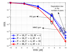
The SER performance is illustrated in Fig. 2c666In practice, in the BALS and KRF methods, optimizing the beamforming weights for data transmission takes place prior to data transmission. However, this optimization step is out of the scope of the present paper. considering different numbers of users , different numbers of antennas , and different numbers of IRS elements . Besides, and . The other parameters are the same as in Fig. 2a. This result shows that the SER decreases as a function of the number of IRS elements. This is an interesting result since no optimization process is carried out, which may further improve the system performance. Fixing , the effect of the number of antennas at the BS and the number of users is shown. By increasing and keeping , the SER improves due to a spatial diversity gain. Changing the roles, i.e., keeping and increasing , the SER degrades as increases. This is intuitive, since the number of channel components to be estimated increases as more users are active in the system.
V Conclusion
We proposed a two-stage closed-form semi-blind receiver for joint channel and symbol estimation in IRS-assisted MU-MIMO systems based on a generalized PARATUCK tensor modeling. The so-called KAKF receiver provides joint estimates of the UTs-IRS and IRS-BS channels and the transmitted symbols with low computational complexity. Compared to its pilot-assisted competitor, KAKF yields more accurate channel estimates while handling time-varying channels.
References
- [1] H. Guo, B. Makki, M. Åström, M.-S. Alouini, and T. Svensson, “Dynamic blockage pre-avoidance using reconfigurable intelligent surfaces,” 2022, arXiv:2201.06659v1 [cs.IT].
- [2] E. Basar and H. V. Poor, “Present and future of reconfigurable intelligent surface-empowered communications [perspectives],” IEEE Signal Process. Mag., vol. 38, no. 6, pp. 146–152, Nov 2021.
- [3] G. T. de Araújo, A. L. F. de Almeida, and R. Boyer, “Channel estimation for intelligent reflecting surface assisted MIMO systems: A tensor modeling approach,” IEEE J. Sel. Topics Signal Process., vol. 15, no. 3, pp. 789–802, Apr 2021.
- [4] X. Chen, J. Shi, Z. Yang, and L. Wu, “Low-complexity channel estimation for intelligent reflecting surface-enhanced massive MIMO,” IEEE Wireless Commun. Lett., vol. 10, no. 5, pp. 996–1000, May 2021.
- [5] B. Zheng, C. You, and R. Zhang, “Intelligent reflecting surface assisted multi-user OFDMA: Channel estimation and training design,” IEEE Trans. Wireless Commun., vol. 19, no. 12, pp. 8315–8329, Dec 2020.
- [6] Z. Wang, L. Liu, and S. Cui, “Channel estimation for intelligent reflecting surface assisted multiuser communications: Framework, algorithms, and analysis,” IEEE Trans. Wireless Commun., vol. 19, no. 10, pp. 6607–6620, Oct 2020.
- [7] A. L. F. de Almeida, G. Favier, and J. C. M. Mota, “A constrained factor decomposition with application to MIMO antenna systems,” IEEE Trans. Signal Process., vol. 56, no. 6, pp. 2429–2442, Jun 2008.
- [8] G. Favier and A. L. F. de Almeida, “Tensor space-time-frequency coding with semi-blind receivers for MIMO wireless communication systems,” IEEE Trans. Signal Process., vol. 62, no. 22, pp. 5987–6002, Nov 2014.
- [9] L. Wei, C. Huang, G. C. Alexandropoulos, and C. Yuen, “Parallel factor decomposition channel estimation in RIS-assisted multi-user MISO communication,” in proc. SAM “2020”, Hangzhou, China, Jun.
- [10] C. Hu, L. Dai, S. Han, and X. Wang, “Two-timescale channel estimation for reconfigurable intelligent surface aided wireless communications,” IEEE Trans. Commun., vol. 69, no. 11, pp. 7736–7747, Nov. 2021.
- [11] B. Sokal, A. L. F. de Almeida, and M. Haardt, “Semi-blind receivers for MIMO multi-relaying systems via rank-one tensor approximations,” Signal Processing, vol. 166, p. 107254, Aug 2019.
- [12] C. Eckart and G. Young, “The approximation of one matrix by another of lower rank,” Psychometrika, vol. 1, no. 3, pp. 211–218, Sep 1936.
- [13] N. P. Pitsianis, “The kronecker product in approximation and fast transform generation,” Ph.D. dissertation, USA, Jan 1997.
- [14] N. Halko, P. G. Martinsson, and J. A. Tropp, “Finding structure with randomness: Probabilistic algorithms for constructing approximate matrix decompositions,” SIAM Review, vol. 53, no. 2, pp. 217–288, 2011.