Superconducting vortex-charge measurement using cavity electromechanics
Abstract
As the magnetic field penetrates the surface of a superconductor, it results in the formation of flux-vortices. It has been predicted that the flux-vortices will have a charged vortex core and create a dipolelike electric field. Such a charge trapping in vortices is particularly enhanced in high-Tc superconductors (HTS). Here, we integrate a mechanical resonator made of a thin flake of HTS Bi2Sr2CaCu2O8+δ into a microwave circuit to realize a cavity-electromechanical device. Due to the exquisite sensitivity of cavity-based devices to the external forces, we directly detect the charges in the flux-vortices by measuring the electromechanical response of the mechanical resonator. Our measurements reveal the strength of surface electric dipole moment due to a single vortex core to be approximately 30 , equivalent to a vortex charge per CuO2 layer of , where is the Bohr radius and is the electronic charge.
The penetration of a magnetic field in type-II superconductors in the form of Abrikosov vortices is well-known [1, 2]. Such vortices have a normal-core of size of the coherence length and each vortex is surrounded by a circulating supercurrent that decays over a characteristic magnetic length scale. It has been predicted that such vortices can trap charges [3, 4, 5, 6]. The origin of the vortex charge can be understood from the difference in the chemical potentials in the superconducting-state and the normal region due to the particle-hole asymmetry. It leads to a redistribution of electrons to maintain the same electrochemical potential across a vortex [7], as shown schematically in Fig. 1(a). Intuitively, the idea of charged vortex core can also be captured by considering the inertial and Lorentz forces acting on the Cooper pairs encircling the normal core, resulting in the depletion of charges from the core [6].
To probe the trapped charge in the vortex core, the high- superconductors (HTS) are particularly attractive. The magnitude of the vortex charge is approximately given by , where is the superconducting gap and is the Fermi energy. The ratio is usually high in HTS . Indeed, in the past, the inference of the charged vortex core has been made on bulk crystals of cuprate superconductors based on techniques probing the sign reversal of Hall coefficient [8], the nuclear quadrupole resonance [9, 10], and instability of the vortex lattice [11]. However, a measurement of the charged vortex core directly measuring its electrostatic field is a challenging task due to its small magnitude and screening by the surrounding charges.
In recent years, nanoelectromechanical systems based approach to probe phase transitions and the thermodynamical properties such as heat capacity, thermal-conductivity, and magnetization have drawn a lot of attention [12, 13, 14, 15, 16]. Particularly, the integration of exfoliated thin flakes into cavity optomechanical and hybrid devices have resulted into enhanced sensitivity to external forces [17, 18, 19]. With these motivations in mind, we apply cavity optomechanical techniques to detect the charges associated with vortices in a high- superconductor by directly probing their electrostatic effect.
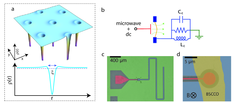
In this work, we use a mechanical resonator of 5 unit cell (UC) thick exfoliated flake of Bi2Sr2CaCu2O8+δ (BSCCO) and integrate it with a microwave cavity to realize a cavity electromechanical device. Due to their low mass, such mechanical resonators have a large coupling with the microwave field of the cavity, which enhances their force sensitivity. Fig. 1(b) shows the electrical equivalent schematic of the device. Such a device is analogous to a Fabry-Perot cavity with a mechanically compliant mirror, where vibrations of the mirror parametrically modulate the resonant frequency of the cavity [20]. We use a superconducting coplanar waveguide-based microwave cavity as shown in Fig. 1(c). The cavity is fabricated by patterning a 200 nm thick sputtered molybdenum and rhenium (MoRe) alloy film on top of intrinsic silicon wafer [21, 22]. The MoRe film has a of 11 K. Near the coupler end of the microwave cavity, a feedline is selectively etched to reduce the MoRe film thickness by 120 nm. The difference in MoRe film thickness provides the clearance to form a suspended mechanical drumhead resonator by the transfer of an exfoliated BSCCO flake. A scanning electron microscopy (SEM) image of the suspended BSCCO flake after the transfer is shown in Fig. 1(d). In this configuration, the BSCCO drumhead-shaped mechanical resonator provides capacitive coupling between the feedline and microwave cavity. In addition, the device design allows application of both alternating current (ac) and direct current (dc) signals through the feedline.
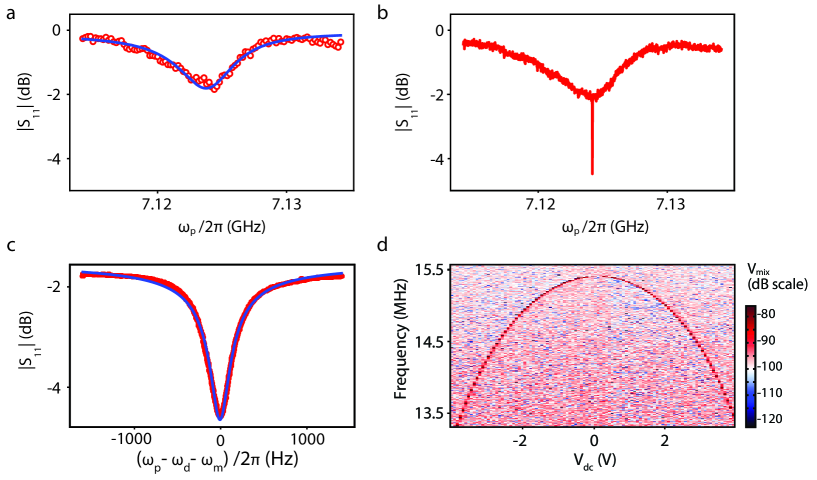
The device is cooled down to 20 mK in a dilution refrigerator with sufficiently attenuated microwave input lines. Additional details of the low-temperature setup are included in the Supporting Information. The reflection from the cavity is measured using a vector network analyzer. Fig. 2(a) shows the measurement of with fundamental resonant mode at 7.124 GHz. The solid line is the fit to the cavity response, yielding the internal and external linewidths of 0.48 MHz and 4.92 MHz, respectively.
For mechanical mode characterization, we drive the BSCCO resonator at its fundamental resonant frequency using the radiation-pressure force. To achieve this, we add a pump signal at along with a weak probe signal near . In the presence of the pump and the probe signals, the mechanical resonator experiences a beating radiation-pressure force near its resonant frequency which drives it coherently [23, 24, 17]. The mechanical motion of the resonator, in turn, modulates the intracavity pump field, resulting in an upconverted signal exactly at the probe frequency. As a coherent process, the upconverted signal interferes with the original probe signal and therefore results in an interference feature with linewidth set by the mechanical losses. Such interference in the cavity reflection is referred to as optomechanically induced absorption (OMIA) [24, 17].
The OMIA interference appears as a sharp absorption feature in the cavity response as shown in Fig. 2(b). A narrow span measurement of the absorption feature is shown in Fig. 2(c). The absorption dip directly manifests the coherently driven mechanical response, and thus allows the complete characterization of the mechanical resonator. From this measurement, we determine the fundamental mechanical mode frequency of 15.383 MHz and linewidth of 165 Hz, corresponding to a quality factor of . The high quality factor is a direct indication of the low contact resistance between the MoRe film and BSCCO [22]. For the cavity-electromechanical device studied here, we estimated the single photon coupling rate to be 30 Hz, where is the quantum zero-point motion of the BSCCO resonator.
Due to the novel electrical design of the device, we can add a dc voltage across the capacitor formed by the BSCCO resonator and the MoRe feedline underneath. While such a scheme has a significant advantage for probing the vortex charge [7], it allows characterization of the BSCCO resonator by an independent technique. A dc signal, , and an ac signal, , can be used to actuate the resonator by a force , where is the separation between BSCCO and the bottom electrode. By using the cavity as an interferometer, the mechanical mode is detected by demodulating the reflected microwave signal from the cavity. Fig. 2(d) shows the plot of demodulated signal as is varied. We observe a quadratic tuning of the mechanical resonant frequency due to capacitive spring softening [25].
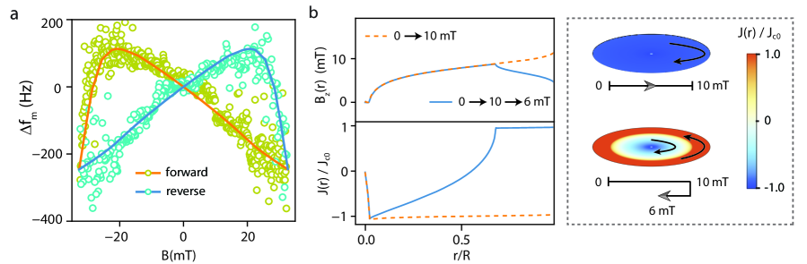
Having described the experimental technique, we measure the electromechanical response when a small magnetic field, perpendicular to the CuO2 plane of the BSCCO crystal is applied. It is represented in Fig. 1(d). We perform OMIA measurements while sweeping the magnetic field in the forward and reverse directions. In the presence of the magnetic field, both the cavity frequency and the mechanical resonant frequency can change. Therefore, we first record the cavity response and readjust the pump frequency based on the measurement of . Fig. 3(a) shows the plot of the mechanical resonant frequency shift at V. We limit the measurements in the range of 32.6 mT due to the reduction in the cavity quality factor at higher fields, which obscure the OMIA feature.
The hysteresis in suggests the role of flux-pinning, the Lorentz force of vortex transferring to the lattice and hence the irreversibility of the frequency shift, similar to the magnetostriction measurements on bulk single crystal of BSCCO [26]. For quantitative analysis, we use the critical state model, which is widely used to explain the magnetization of HTS [27, 28]. Here the maximum sheet current is capped at a critical current which in general could be magnetic field dependent [29, 30]. Due to this sheet current and the local magnetic field , the flake experiences a Lorentz force in the lateral direction. It results in a magnetic field dependent tension in the flake and hence a change in the mechanical resonant frequency as observed in Fig. 3(a).
We use a local critical sheet current as , where is the local magnetic field in the BSCCO plane, and the maximum critical current and characteristic magnetic field are two model parameters [29, 30]. We note that here BSCCO resonator thickness (5 UC) is much smaller than the London penetration length [31]. Therefore, a small field can push the flux-front, the boundary between the Meissner phase and the mixed phase, to nearly the center of the BSCCO flake. We assume that the steady-state critical currents remain confined to the boundaries of the BSCCO flake. To keep the calculations simple, we treat BSCCO as a thin circular plate. Calculation for the realistic geometry would only results in a scaling factor. Our model neglects geometrical [32] or Bean-Livingston barrier [33]. Furthermore, we assume no interaction between the vortex lines passing through the MoRe film (bottom capacitor plate) and BSCCO resonator (top capacitor plate).
To calculate the force experienced by the suspended part of the BSCCO flake, we first calculate the radial profile of the sheet current density and [34]. The Lorentz force on the suspended part of the BSCCO flake is then estimated by , resulting in a net stress in the flake. The stress can be compressive or tensile depending on the sign of the integral. The Lorentz-force induced stress can be used to compute the frequency shift of mechanical resonator, as shown by the solid lines in Fig. 3(a). The radial profiles of the local magnetic field and the normalized critical current are shown in Fig. 3(b). For these calculations, we have used the critical current density of [35, 36] and mT [37]. Additional details of the model are included in the Supporting Information..
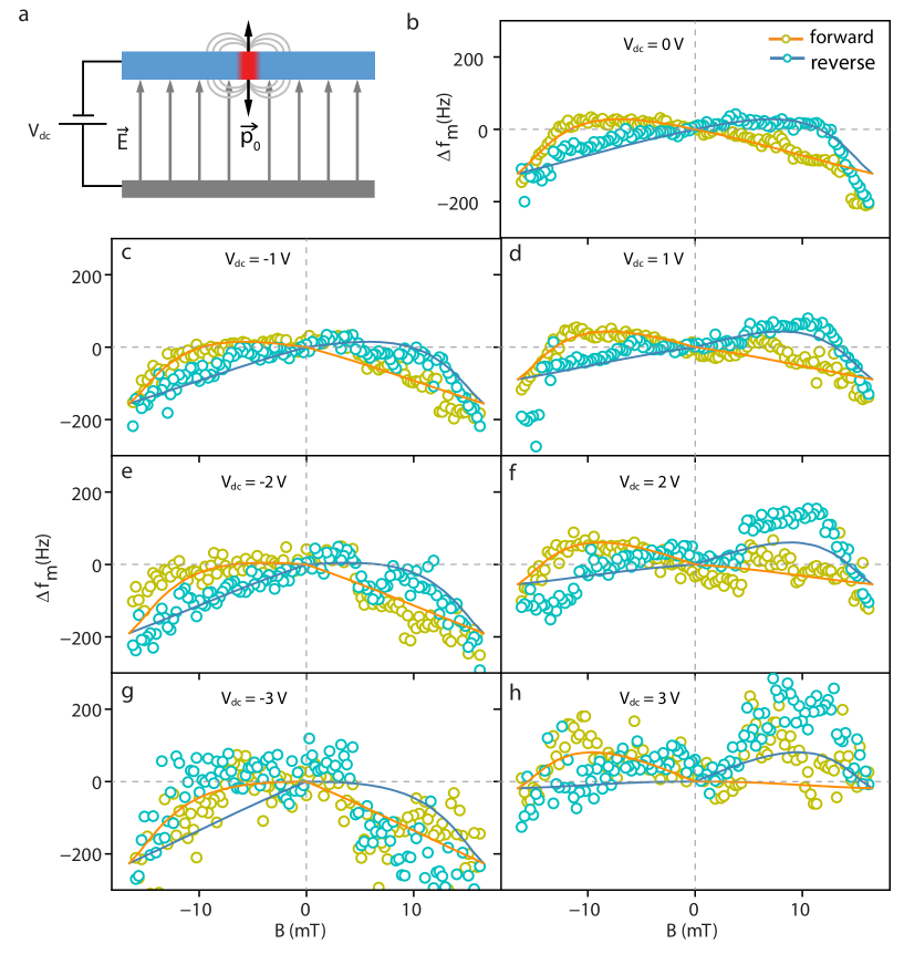
To probe the charge associated with vortices, their interaction with the electrostatic field setup by a dc voltage plays a crucial role. Therefore, we now turn our focus on the mechanical response when is applied as shown schematically in Fig. 4(a). The plots of at different applied across the BSCCO resonator are shown in Fig. 4(b-h). For these measurements, we sweep the magnetic field in 16.3 mT range due to the reduction in the mechanical quality factor at higher , which limits the measurement of mechanical response using OMIA technique. The measurement of shows a clear asymmetry depending on the sign of . In addition, the overall dispersion with the magnetic field is enhanced at large negative dc voltages as compared to the case when is positive. The asymmetry in the electromechanical response with respect to the sign of (left vs right panels in Fig. 4(b-h) clearly suggests an electrostatic origin. This could be explained by considering the charge trapped in the vortex core. The charge per copper-oxide layer inside the vortex core is given by [4, 7]. Using , and a CuO2-plane spacing of 0.75 nm for BSCCO [38], a typical estimate of can be made. It is equivalent to a line charge density of 0.013 /nm.
In the limit , where is the thickness of BSCCO, the net effect of the vortex line charge can effectively be captured by considering an equivalent surface electric dipole [7]. To understand our observations, we consider the interaction of surface dipoles with the electric field set up by . A dc voltage across the capacitor modifies the interaction energy by , where is the electric field between the capacitor plates, and hence leads to an electromechanical coupling. As magnetic field is increased, the number of vortices penetrating the suspended part of the BSCCO increases, as , where is the superconducting flux quantum and is the radius of the suspended part of BSCCO. By considering a uniform distribution of the vortices on a triangular lattice across the BSCCO resonator, their contribution to the electromechanical energy can be calculated by summing over all the vortices present in the suspended part.
We include the electric dipole contribution along with the elastic, and the capacitive contribution to the total electromechanical energy . Therefore, the effective spring constant and hence the mechanical resonant frequency can be determined. The solid lines in Fig. 4(b-h) show the calculated by including a dc voltage dependent energy in the electromechanical response. Here the curves are plotted taking a dipole magnitude of with a positively charged core, where m is the Bohr radius. It is important to point out here that the sign of the vortex core charge is determined by the oxygen doping level in the BSCCO crystal. For an overdoped (oxygen-rich) crystal, it is expected to be positive [39]. For a positively charged vortex core, the surface dipole moment points in an outward direction from the BSCCO surface regardless to the direction of the applied magnetic field. Therefore, the electromechanical response is expected show an asymmetry with respect to the electric field created by . For a positively charged vortex core, the mechanical resonant frequency is expected to show a softening (hardening) behavior for negative (positive) voltages as observed in the measurement. Details of the electromechanical spring constant calculation are provided in the Supporting Information. In next paragraph, we calculate the line charge density equivalent to this surface dipole moment and make a comparison with the values reported in the literature.
Following ref. [7], the charge density profile across a vortex core can be written as , where is the Bohr radius, and is the particle-hole asymmetry parameter. The line charge density in the vortex core, therefore, is given by . Such a charge redistribution is equivalent to a surface dipole pointing normal to the superconducting surface and having a magnitude of . Therefore, the line charge can be related to the dipole moment as , where is the effective mass ratio of the charge carrier. Using nm [40], [41], and nm, we obtain /nm, which is equivalent to a charge of per CuO2 layer.
Our estimation of the charge per copper oxide layer is consistent with the earlier measurements made on YBCO using the nuclear quadrupole resonance technique [9]. Both the experiments reveal a larger value of the vortex charge than that obtained via the theoretical predictions. The difference between the vortex charge magnitude from the experiments and the theory can have several interesting origins. First, it suggests that the gap anisotropy and Fermi surface curvature might be playing an important role [42]. Second, given the ultralow temperature in this experiment, the quantum effects in the vortex could become relevant. Finally, the nature of the vortex core could be different from the metallic phase [43, 44].
To summarize, we show clear evidence for the trapped-charges in the vortex core probed using a cavity optomechanical device. The magnitude of the equivalent dipole is higher than the estimates from the BCS-theory while considering Thomas-Fermi screening. Such a difference opens up new possibilities to revisit the vortex-charge problem in atomically thin superconductors. Furthermore, our experiment and novel device approach show the advantages of integrating exfoliated thin flake into the cavity optomechanical devices for sensitive measurement of the thermodynamical properties. With minor modifications in the design, such technique could further be extended to other systems involving topological charge [45] or bosonic Landau levels [46]. This work thus opens up a new avenue to study quantum phase transitions as external parameters are varied.
.1 Acknowledgment
The authors thank Eli Zeldov, Subir Sachdev and Vijay Shenoy for insightful discussions. The authors also thank D. Jangade and A. Thamizhavel for their help during the crystal growth. M.M.D. acknowledges the Department of Atomic Energy of the Government of India under Grant No. 12-RD-TFR-5.10-0100, DST Nanomission under Grant No. SR/NM/NS-45/2016 and SERB CORE grant CRG/2020/003836. V.S. acknowledges the research support under the Core Research Grant CRG/2018/001132 by DST and ISTC-0395 by STC-ISRO. S.K.S. acknowledges device fabrication facilities at the Department of Physics, and CeNSE, IISc-Bangalore funded by Department of Science and Technology (DST), Government of India.
References
- Ketterson and Song [1999] Ketterson, J. B.; Song, S. N. Superconductivity; Cambridge University Press: Cambridge, 1999.
- Abrikosov [2004] Abrikosov, A. A. Nobel Lecture: Type-II superconductors and the vortex lattice. Reviews of Modern Physics 2004, 76, 975–979.
- Caroli et al. [1964] Caroli, C.; De Gennes, P. G.; Matricon, J. Bound Fermion states on a vortex line in a type II superconductor. Physics Letters 1964, 9, 307–309.
- Khomskii and Freimuth [1995] Khomskii, D. I.; Freimuth, A. Charged Vortices in High Temperature Superconductors. Physical Review Letters 1995, 75, 1384–1386.
- Feigel’man et al. [1995] Feigel’man, M.; Geshkenbein, V.; Larkin, A.; Vinokur, V. M. Sign change of the flux-flow Hall effect in HTSC. JETP Letters 1995, 62, 834–840.
- Koláček et al. [2001] Koláček, J.; Lipavský, P.; Brandt, E. H. Charge Profile in Vortices. Physical Review Letters 2001, 86, 312–315.
- Blatter et al. [1996] Blatter, G.; Feigel’man, M.; Geshkenbein, V.; Larkin, A.; van Otterlo, A. Electrostatics of Vortices in Type-II Superconductors. Physical Review Letters 1996, 77, 566–569.
- Hagen et al. [1991] Hagen, S. J.; Lobb, C. J.; Greene, R. L.; Eddy, M. Flux-flow Hall effect in superconducting films. Physical Review B 1991, 43, 6246–6248.
- Kumagai et al. [2001] Kumagai, K.-i.; Nozaki, K.; Matsuda, Y. Charged vortices in high-temperature superconductors probed by NMR. Physical Review B 2001, 63, 144502.
- Mitrović et al. [2001] Mitrović, V. F.; Sigmund, E. E.; Eschrig, M.; Bachman, H. N.; Halperin, W. P.; Reyes, A. P.; Kuhns, P.; Moulton, W. G. Spatially resolved electronic structure inside and outside the vortex cores of a high-temperature superconductor. Nature 2001, 413, 501–504.
- Mounce et al. [2011] Mounce, A. M.; Oh, S.; Mukhopadhyay, S.; Halperin, W. P.; Reyes, A. P.; Kuhns, P. L.; Fujita, K.; Ishikado, M.; Uchida, S. Charge-induced vortex lattice instability. Nature Physics 2011, 7, 125–128.
- Bolle et al. [1999] Bolle, C. A.; Aksyuk, V.; Pardo, F.; Gammel, P. L.; Zeldov, E.; Bucher, E.; Boie, R.; Bishop, D. J.; Nelson, D. R. Observation of mesoscopic vortex physics using micromechanical oscillators. Nature 1999, 399, 43–46.
- Schwab et al. [2000] Schwab, K.; Henriksen, E. A.; Worlock, J. M.; Roukes, M. L. Measurement of the quantum of thermal conductance. Nature 2000, 404, 974–977.
- Chen et al. [2016] Chen, C.; Deshpande, V. V.; Koshino, M.; Lee, S.; Gondarenko, A.; MacDonald, A. H.; Kim, P.; Hone, J. Modulation of mechanical resonance by chemical potential oscillation in graphene. Nature Physics 2016, 12, 240–244.
- Morell et al. [2019] Morell, N.; Tepsic, S.; Reserbat-Plantey, A.; Cepellotti, A.; Manca, M.; Epstein, I.; Isacsson, A.; Marie, X.; Mauri, F.; Bachtold, A. Optomechanical Measurement of Thermal Transport in Two-Dimensional MoSe2 Lattices. Nano Letters 2019, 19, 3143–3150.
- Šiškins et al. [2020] Šiškins, M.; Lee, M.; Mañas-Valero, S.; Coronado, E.; Blanter, Y. M.; van der Zant, H. S. J.; Steeneken, P. G. Magnetic and electronic phase transitions probed by nanomechanical resonators. Nature Communications 2020, 11, 2698.
- Singh et al. [2014] Singh, V.; Bosman, S. J.; , B. H.; Blanter, Y. M.; Castellanos-Gomez, A.; Steele, G. A. Optomechanical coupling between a multilayer graphene mechanical resonator and a superconducting microwave cavity. Nature Nanotechnology 2014, 9, 820–824.
- Weber et al. [2014] Weber, P.; Güttinger, J.; Tsioutsios, I.; Chang, D. E.; Bachtold, A. Coupling Graphene Mechanical Resonators to Superconducting Microwave Cavities. Nano Letters 2014, 14, 2854–2860.
- Reserbat-Plantey et al. [2016] Reserbat-Plantey, A.; Schädler, K. G.; Gaudreau, L.; Navickaite, G.; Güttinger, J.; Chang, D.; Toninelli, C.; Bachtold, A.; Koppens, F. H. L. Electromechanical control of nitrogen-vacancy defect emission using graphene NEMS. Nature Communications 2016, 7, 10218.
- Aspelmeyer et al. [2014] Aspelmeyer, M.; Kippenberg, T. J.; Marquardt, F. Cavity optomechanics. Reviews of Modern Physics 2014, 86, 1391–1452.
- Singh et al. [2014] Singh, V.; Schneider, B. H.; Bosman, S. J.; Merkx, E. P. J.; Steele, G. A. Molybdenum-rhenium alloy based high-Q superconducting microwave resonators. Applied Physics Letters 2014, 105, 222601.
- Sahu et al. [2019] Sahu, S. K.; Vaidya, J.; Schmidt, F.; Jangade, D.; Thamizhavel, A.; Steele, G.; Deshmukh, M. M.; Singh, V. Nanoelectromechanical resonators from high- superconducting crystals of . 2D Materials 2019, 6, 025027.
- Weis et al. [2010] Weis, S.; Rivière, R.; Deléglise, S.; Gavartin, E.; Arcizet, O.; Schliesser, A.; Kippenberg, T. J. Optomechanically Induced Transparency. Science 2010, 330, 1520–1523.
- Zhou et al. [2013] Zhou, X.; Hocke, F.; Schliesser, A.; Marx, A.; Huebl, H.; Gross, R.; Kippenberg, T. J. Slowing, advancing and switching of microwave signals using circuit nanoelectromechanics. Nature Physics 2013, 9, 179–184.
- Kozinsky et al. [2006] Kozinsky, I.; Postma, H. W. C.; Bargatin, I.; Roukes, M. L. Tuning nonlinearity, dynamic range, and frequency of nanomechanical resonators. Applied Physics Letters 2006, 88, 253101.
- Ikuta et al. [1993] Ikuta, H.; Hirota, N.; Nakayama, Y.; Kishio, K.; Kitazawa, K. Giant magnetostriction in single crystal in the superconducting state and its mechanism. Physical Review Letters 1993, 70, 2166–2169.
- Bean [1962] Bean, C. P. Magnetization of Hard Superconductors. Physical Review Letters 1962, 8, 250–253.
- Brandt [1996] Brandt, E. H. Superconductors of finite thickness in a perpendicular magnetic field: Strips and slabs. Physical Review B 1996, 54, 4246–4264.
- Chen and Goldfarb [1989] Chen, D.; Goldfarb, R. B. Kim model for magnetization of type‐II superconductors. Journal of Applied Physics 1989, 66, 2489–2500.
- Senoussi et al. [1988] Senoussi, S.; Osséna, M.; Collin, G.; Campbell, I. A. Exponential and decay of the critical current density in single crystals. Physical Review B 1988, 37, 9792–9795.
- Harshman et al. [1991] Harshman, D. R.; Kleiman, R. N.; Inui, M.; Espinosa, G. P.; Mitzi, D. B.; Kapitulnik, A.; Pfiz, T.; Williams, D. L. Magnetic penetration depth and flux dynamics in single-crystal . Physical Review Letters 1991, 67, 3152–3155.
- Zeldov et al. [1994] Zeldov, E.; Larkin, A. I.; Geshkenbein, V. B.; Konczykowski, M.; Majer, D.; Khaykovich, B.; Vinokur, V. M.; Shtrikman, H. Geometrical Barriers in High-Temperature Superconductors. Physical Review Letters 1994, 73, 1428–1431.
- Bean and Livingston [1964] Bean, C. P.; Livingston, J. D. Surface Barrier in Type-II Superconductors. Physical Review Letters 1964, 12, 14–16.
- Shantsev et al. [1999] Shantsev, D. V.; Galperin, Y. M.; Johansen, T. H. Thin superconducting disk with -dependent : Flux and current distributions. Physical Review B 1999, 60, 13112–13118.
- You et al. [2005] You, L. X.; Yurgens, A.; Winkler, D. Superconducting critical current of a single plane in a single crystal. Physical Review B 2005, 71, 224501.
- Stangl et al. [2021] Stangl, A.; Palau, A.; Deutscher, G.; Obradors, X.; Puig, T. Ultra-high critical current densities of superconducting thin films in the overdoped state. Scientific Reports 2021, 11.
- Sunwong et al. [2011] Sunwong, P.; Higgins, J. S.; Hampshire, D. P. Angular, Temperature, and Strain Dependencies of the Critical Current of DI-BSCCO Tapes in High Magnetic Fields. IEEE Transactions on Applied Superconductivity 2011, 21, 2840–2844.
- Zhao et al. [2019] Zhao, S. F.; Poccia, N.; Panetta, M. G.; Yu, C.; Johnson, J. W.; Yoo, H.; Zhong, R.; Gu, G.; Watanabe, K.; Taniguchi, T.; Postolova, S. V.; Vinokur, V. M.; Kim, P. Sign-Reversing Hall Effect in Atomically Thin High-Temperature Superconductors. Physical Review Letters 2019, 122, 247001.
- Chen et al. [2002] Chen, Y.; Wang, Z. D.; Zhu, J.-X.; Ting, C. S. Vortex Charges in High-Temperature Superconductors. Physical Review Letters 2002, 89, 217001.
- Naughton et al. [1988] Naughton, M. J.; Yu, R. C.; Davies, P. K.; Fischer, J. E.; Chamberlin, R. V.; Wang, Z. Z.; Jing, T. W.; Ong, N. P.; Chaikin, P. M. Orientational anisotropy of the upper critical field in single-crystal and . Physical Review B 1988, 38, 9280–9283.
- Orlando et al. [2018] Orlando, M. T. D.; Rouver, A. N.; Rocha, J. R.; Cavichini, A. S. Correlation among the effective mass (), and of superconducting cuprates in a Casimir energy scenario. Physics Letters A 2018, 382, 1486–1491.
- Ueki et al. [2016] Ueki, H.; Kohno, W.; Kita, T. Vortex-Core Charging Due to the Lorentz Force in a -Wave Superconductor. Journal of the Physical Society of Japan 2016, 85, 064702.
- Arovas et al. [1997] Arovas, D. P.; Berlinsky, A. J.; Kallin, C.; Zhang, S.-C. Superconducting Vortex with Antiferromagnetic Core. Physical Review Letters 1997, 79, 2871–2874.
- Knapp et al. [2005] Knapp, D.; Kallin, C.; Ghosal, A.; Mansour, S. Antiferromagnetism and charged vortices in high- superconductors. Physical Review B 2005, 71, 064504.
- Jiang et al. [2017] Jiang, W.; Zhang, X.; Yu, G.; Zhang, W.; Wang, X.; Benjamin Jungfleisch, M.; Pearson, J. E.; Cheng, X.; Heinonen, O.; Wang, K. L.; Zhou, Y.; Hoffmann, A.; te Velthuis, S. G. E. Direct observation of the skyrmion Hall effect. Nature Physics 2017, 13, 162–169.
- Devarakonda et al. [2021] Devarakonda, A.; Suzuki, T.; Fang, S.; Zhu, J.; Graf, D.; Kriener, M.; Fu, L.; Kaxiras, E.; Checkelsky, J. G. Signatures of bosonic Landau levels in a finite-momentum superconductor. Nature 2021, 599, 51–56.