Channel Estimation with Simultaneous Reflecting and Sensing Reconfigurable Intelligent Metasurfaces
Abstract
Reconfigurable Intelligent Surfaces are envisioned to play a key role in future wireless communications, enabling programmable radio propagation environments. They are usually considered as nearly passive planar structures that operate as adjustable reflectors, giving rise to a multitude of implementation challenges, including an inherent difficulty in estimating the underlying wireless channels. In this paper, we propose the concept of Hybrid RISs (HRISs), which do not solely reflect the impinging waveform in a controllable fashion, but are also capable of sensing and processing a portion of it via some active reception elements. We first present implementation details for this novel metasurface architecture and propose a simple model for its operation, when considered for wireless communications. As an indicative application of HRISs, we formulate and solve the individual channels identification problem for the uplink of multi-user HRIS-empowered systems. Our numerical results showcase that, in the high signal-to-noise regime, HRISs enable individual channel estimation with notably reduced amounts of pilots, compared to those needed when using a purely reflective RIS that can only estimate the cascaded channel.
Index terms— Reconfigurable intelligent surfaces, metasurfaces, channel estimation, sensing, smart radio environments.
I Introduction
An emerging technology for the future sixth Generation (6G) of wireless communications, enabling dynamically programmable signal propagation over the wireless medium [1], is the RISs [2, 3]. Those planar structures typically consist of multiple metamaterial elements, whose ElectroMagnetic (EM) properties can be externally controlled in a nearly passive manner, allowing them to realize various reflection and scattering profiles [4].
The passive nature of RISs implies that they can only act as adjustable reflectors, thus, they can neither receive nor transmit their own data. While RISs enable smart programmable environments [1], their purely passive operation also induces notable challenges on the communicating entities. For instance, the introduction of an RIS implies that a signal transmitted from each User Terminal (UT) to the Base Station (BS) undergoes at least two channels: the UT-RIS and RIS-BS channels. Estimating these individual channels is a challenging task due to the passive nature of RISs. Consequently, the common approach in the field of RIS-empowered networks is to estimate only the entangled combined effect of these channels, known as the cascaded channel [5, 6], which limits the transmission scheme design and restricts network management flexibility [7]. For example, the individual channels between UT-RIS and RIS-BS are needed for some precoding designs, as discussed in [8]. In fact, it was recently proposed to equip RISs with minimal receive Radio-Frequency (RF) chains to overcome the communication challenges associated with their purely passive counterparts [9, 10].
Active metasurfaces have recently emerged as a appealing technology for realizing low-cost and low-power large-scale Multiple-Input Multiple-Output (MIMO) antennas [11]. Dynamic Metasurface Antennas pack large numbers of tunably radiative metamaterials on top of waveguides, resulting in MIMO transceivers with advanced analog processing capabilities [12, 13, 14]. While the implementation of DMAs differs from passive RISs, the similarity in the structure of the metamaterial elements between them indicates the feasibility of designing hybrid reflecting and sensing elements. This motivates studying the benefits from such a hybrid metasurface architecture, as an efficient means of facilitating RIS-empowered wireless communications.
In this work, we present an initial study on the potential gains of using Hybrid reflecting and sensing RISs (HRISs) in multi-user wireless communications. To that aim, we begin by discussing the feasibility of the concept of hybrid metamaterials, providing a high-level description of their design. Then, we propose a model for HRISs which captures their ability to simultaneously reflect and receive the incoming signal in an element-by-element controllable manner. To quantify the benefits of HRISs, we study the individual channels estimation problem. Our results show that, in the high Signal-to-Noise Ratio (SNR) regime, HRISs yield achievable Mean-Squared Error (MSE) performance using smaller numbers of pilot signals than those typically required in networks with reflective RISs to estimate solely the cascaded channel [5]. Our numerical evaluations also characterize the inherent tradeoff between the ability to estimate the individual channels and tunable reflection, which is balanced by the HRIS configuration.
Throughout the paper, we use boldface lower-case and upper-case letters for vectors and matrices, respectively. Calligraphic letters are used for sets. The vectorization operator, transpose, conjugation, Hermitian transpose, trace, and expectation are written as , , , , , and , respectively. denotes a block diagonal matrix with diagonal blocks given by .
II HRISs and System Modeling
II-A Hybrid Metasurfaces
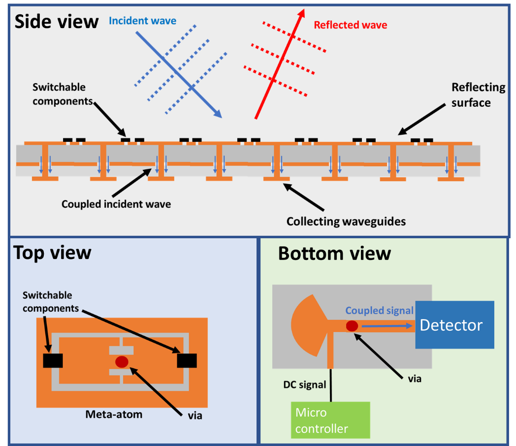
A rich body of literature has examined the implementation of solely reflective RISs. A variety of implementations has been recently presented in [4], ranging from RISs that change the wave propagation inside a multi-scattering environment for improving the received signal, to those which realize anomalous reflection, such that the reflected beam does not follow Snell’s law and is directed towards desired directions. In all these efforts, the RIS is not designed to sense the impinging signal. Nonetheless, metasurfaces can be designed to operate in a hybrid reflecting and sensing manner. Such hybrid operation requires that each metarsurface element is capable of simultaneously reflecting a portion of the impinging signal and receiving a portion of it in a controlable manner. As illustrated in Fig. 1, a simple mechanism for implementing such an operation is to couple each element to a waveguide. The signals coupled to the waveguides are then measured by receive RF chains and used to determine the necessary information about the channel. A detailed description of the practical implementation of such hybrid metamaterials can be found in [15]. In this paper, we are interested in examining the potential benefits of HRISs in wireless communications. To this end, we present in the sequel a simple model capturing their simultaneous reflecting and sensing operation.
II-B HRIS Operation Modeling
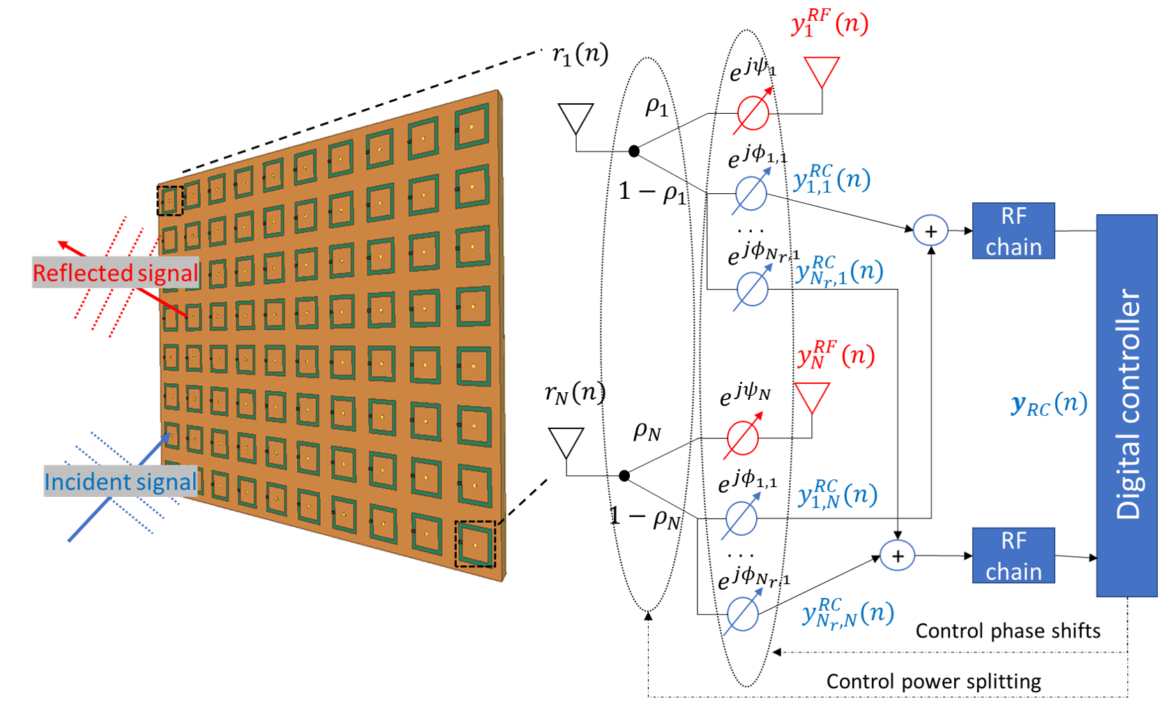
To model the dual reflection-reception operation of HRISs, we consider a hybrid metasurface comprised meta-atom elements, which are connected to a digital controller via receive RF chains. Let denote the radiation observed by the -th HRIS element () at the -th time instance. A portion of this signal, dictated by the parameter , is reflected with a controllable phase shift , and thus the reflected signal from the -th element can be mathematically expressed as:
| (1) |
The remainder of the observed signal is locally processed, via analog combining and digital processing. The signal forwarded to the -th RF chain via combining, with , from the -th element is consequently given by
| (2) |
where is the adjustable phase that models the joint effect of the response of the -th meta-atom and the subsequent analog phase shifting. The proposed HRIS operation model is illustrated in Fig. 2. It is noted that the operation of the conventional passive and reflective RISs can be treated as a special case of our proposed Hybrid Reconfigurable Intelligent Surface (HRIS) architecture, by setting all ’s in (1) equal to 1. Meanwhile, compared to existing relay techniques, there are two major advantages with our novel architecture. First, HRISs allow full-duplex operation (i.e., simultaneous reflection and reception) without inducing self interference, which is unavoidable in full-duplex relay systems. Second, HRISs require low power consumption since they do not need active power amplifiers.
The resulting signal model at HRIS can be expressed in vector form, as follows. By stacking the received and the reflected signals at the vectors and , respectively, it follows from (1) that
| (3) |
with . Similarly, by letting be the reception output vector at HRIS, it holds that
| (4) |
where the matrix represents the analog combining carried out at the HRIS receiver. When the -th meta-atom element is connected to the -th RF chain, then , while when there is no such connection (e.g., for partially-connected combiners) it holds .
The reconfigurability of HRISs implies that the parameters ’s and the phase shifts ’s and ’s are externally controllable. It is noted that when an element is connected to multiple receive RF chains, then additional dedicated analog circuitry (e.g., conventional networks of phase shifters) is required to allow the signal to be forwarded with a different phase shift to each RF chain, at the possible cost of additional power consumption. Nonetheless, when each element feeds a single RF chain, then the model in Fig. 2 can be realized without such circuitry by placing the elements on top of separated waveguides (see, e.g., [11]).
II-C HRIS-Assisted Channel Estimation
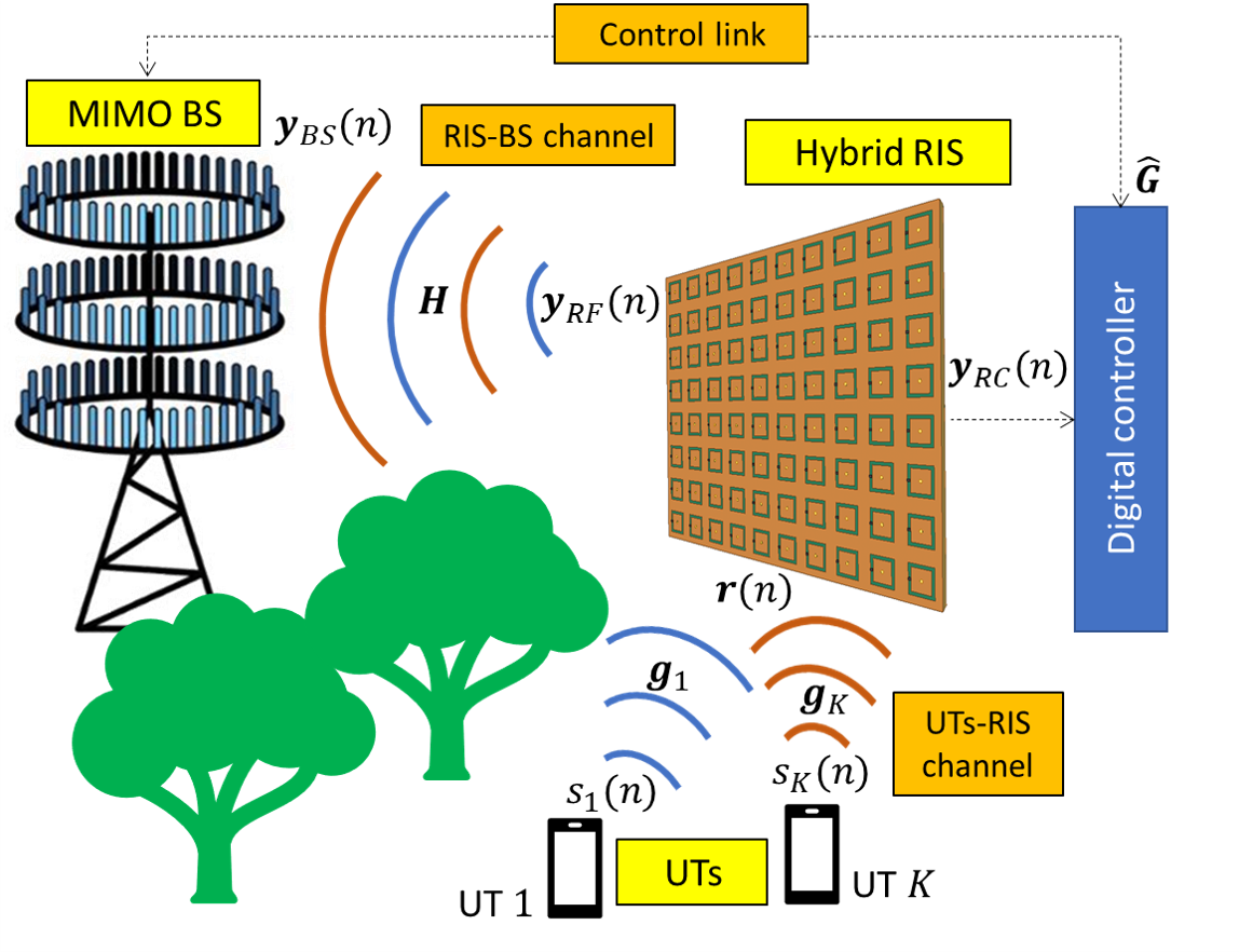
In order to investigate the capabilities of the proposed HRIS architecture in facilitating multi-user wireless communications, we henceforth consider the problem of channel estimation in HRIS-empowered systems, being one of the main challenges associated with conventional nearly passive and reflective RISs [7]. In particular, we consider an uplink multi-user MIMO system, where a BS equipped with antenna elements serves single antenna UTs with the assistance of a HRIS. This setup is graphically presented in Fig. 3. We assume that there is no direct link between the BS and any of UTs, and thus communication is done only via the HRIS. Let be the channel between the BS and HRIS, and be the channel between the -th user () and HRIS. We consider independent and identically distributed (i.i.d.) Rayleigh fading for all channels with and having i.i.d. zero-mean Gaussian entries with variances and , respectively, denoting the pathlosses.
Channel estimation with an HRIS can be carried out in a time division duplexing fashion using orthogonal pilots with . The signal observed by the HRIS is given by the vector with and . The signal locally processed by the HRIS is given by (4) after being corrupted by additive white Gaussian noise (AWGN), which models the thermal noise induced in signal acquisition. Consequently, the signals received at the HRIS at the -th channel estimation instance are given by:
| (5) |
where is the AWGN with entries of variance . Note that in (5), the configuration of the HRIS combining parameters, e.g., and , are allowed to change over time. Similarly, the signal received at the BS using (3) during the channel estimation phase can be expressed as:
| (6) |
where is AWGN with entries of variance .
As in conventional RIS-empowered wireless networks, e.g., [2], we assume that the BS maintains a high-throughput direct link with the HRIS. For passive RISs, this link is used for controlling the RIS reflection pattern. In HRISs which have receiving capabilities, this link is also used for conveying information from the HRIS to the BS. Therefore, we focus on channel estimation carried out at both the HRIS side as well as by the BS. Our goal is to characterize the achievable MSE in recovering the UTs-HRIS channel from (5); along with the MSE in estimating at the BS from (6) and from the estimate of , denoted , provided by the HRIS.
III Identification of Individual Channels
III-A Channel Estimation without Noise
We begin by considering communications carried out in the ideal case, where the noise terms in (5) and (6) are negligible, i.e., . In such scenarios, one should be able to fully recover both and from the observed signals and . The number of pilots required to achieve accurate recovery is stated in the following proposition (its proof will be provided in the extended version of this paper):
Proposition 1.
In the high SNR regime, and can be accurately recovered when the number of pilots satisfies
| (7) |
Proposition 1 reveals the intuitive benefit of HRISs in facilitating channel estimation from reduced number of pilots, as compared to existing techniques for estimating the cascaded UTs-RIS-BS channels (e.g., [5]). For instance, for a multi-user MIMO system with BS antennas, HRIS RF chains, UTs, and HRIS elements, the adoption of an HRIS allows recovering and separately using pilots. For comparison, the method proposed in [5] requires transmitting over pilots to identify the cascaded channel coefficients and . This reduction in pilot signals is directly translated into improved spectral efficiency, as less pilots are to be transmitted in each coherence duration.
III-B Channel Estimation with Noise
The characterization of the number of required pilots in Proposition 1 provides an initial understanding of the HRISs’ capability in providing efficient channel estimation. However, as Proposition 1 considers an effectively noise-free setup, it is invariant of the fact that HRISs split the power of the received signal between the reflected and received components. In the presence of noise, this division of the signal power may result in SNR degradation. Therefore, we next study channel estimation using HRISs in the presence of noise.
Let be the vector generated by stacking and define . It holds from (5) that can be written as a linear function of the UTs-HRIS channel , as follows:
| (8) |
where results from stacking , while the entries of the matrix are given and by . Similarly, by letting and be the stacking of and , respectively, and defining , we obtain
| (9) |
In (9), the matrix is consisting of the entries: .
We next use the latter expressions formulations to quantify the achievable MSE in estimating the individual UTs-HRIS and HRIS-BS channels for a fixed HRIS configuration , , and . We focus here on the case where these parameters remain constant during the channel estimation phase, and the noise powers at the HRIS and BS are of the same level, i.e., . We begin by characterizing the achievable MSE performance in recovering , denoted by .
Theorem 1.
The UTs-HRIS channel can be recovered with the following MSE performance:
where and , with denoting each UT’s transmit power for pilots.
Theorem 1 allows to compute the achievable MSE in estimating at the HRIS side for a given configuration of its reception phase profile, determined by and . The estimated will be conveyed to the BS (via their control link), and is used along with the observed reflected by the HRIS to recover . When is accurately estimated, the BS can recover up to the MSE stated in the following theorem.
Theorem 2.
The HRIS-BS channel can be recovered with the following MSE performance with :
Theorems 1 and 2, whose proofs will be given in the extended version of this paper, allow to evaluate the achievable MSE in recovering the individual channels and . The fact that these MSEs are given as functions of the HRIS parameters enables us to numerically optimize its configuration. In Section IV, our numerical evaluation of the MSEs reveals the fundamental tradeoff between the ability to recover and , which is dictated mostly by the parameter determining what portion of the impinging signal is reflected.
III-C Discussion
The fact that HRISs require less pilots naturally follows from their ability to provide additional receive ports, while simultaneously acting as a reflector. It is noted that our results in the previous subsections are obtained assuming that the UTs-HRIS channel is estimated at the HRIS, and its estimate is forwarded to the BS. For this reason, Proposition 1 relies on having the HRIS configuration change over time, as for static and , one can only recover via (5), from which cannot be computed when the HRIS has less RF chains than elements, i.e., . Furthermore, exploiting the HRIS as an additional non-co-located receive port can also facilitate data transmission once the channels are estimated, though in this case one would also have to account for possible rate limitations on the HRIS-BS link. We leave the study of these additional usages of HRISs for future research.
The majority of the existing literature about channel estimation in RIS-empowered communications has mainly focused on estimating the cascaded channel, which represents the joint effect of the UTs-RIS and RIS-BS channels in an entangled manner. Estimating the cascaded channel using reflective RISs typically requires a large amount of pilots in each coherence duration of the channel. Furthermore, knowledge of the individual channels enables the design of flexible and improved transmission and management schemes, compared to knowing solely the cascaded channel [7]. In fact, several hardware architectures were proposed to provide some information processing to be carried out at the RIS side, by adding dedicated reception-only hardware [9]-[10], The HRIS architecture balances reception and reflection in a controllable manner. In particular, HRISs can be configured to be divided into purely reflective and purely receptive elements, as in [10], while providing additional degrees of freedom due to the ability to adjust the power splitting coefficients .
The study of HRISs, combined with the numerical evaluations in Section IV, only reveal a portion of the potential of HRISs in facilitating wireless communication over programmable environments. To further understand the contribution of HRISs, one should also study their impact on data transmission, as well as consider the presence of an additional direct channel between the UTs and the BS. Furthermore, the simplified model used in this work is based on the hybrid metamaterial model presented in [15], and additional experimental studies of this model are required to formulate a more accurate physically-compliant model for the behavior of HRISs. These extensions are left for future work.
IV Numerical Results
In this section, we numerically evaluate the channel estimation performance of the proposed HRIS-empowered multi-user MIMO systems. In our simulations, a BS with antennas serves UTs via an HRIS with elements. The pathlosses of the individual channels and are modeled as and , where dB denotes a constant pathloss at the reference distance m, while and are the distances from the HRIS to BS and the th UT, respectively. The pathloss factors were set as and . We consider a 2D Cartesian coordinate system in which the BS and the HRIS are respectively located at points (0, 0) and (0, 50 m), while the users are randomly generated in an area centered at (30 m, 50 m) with a radius of m.
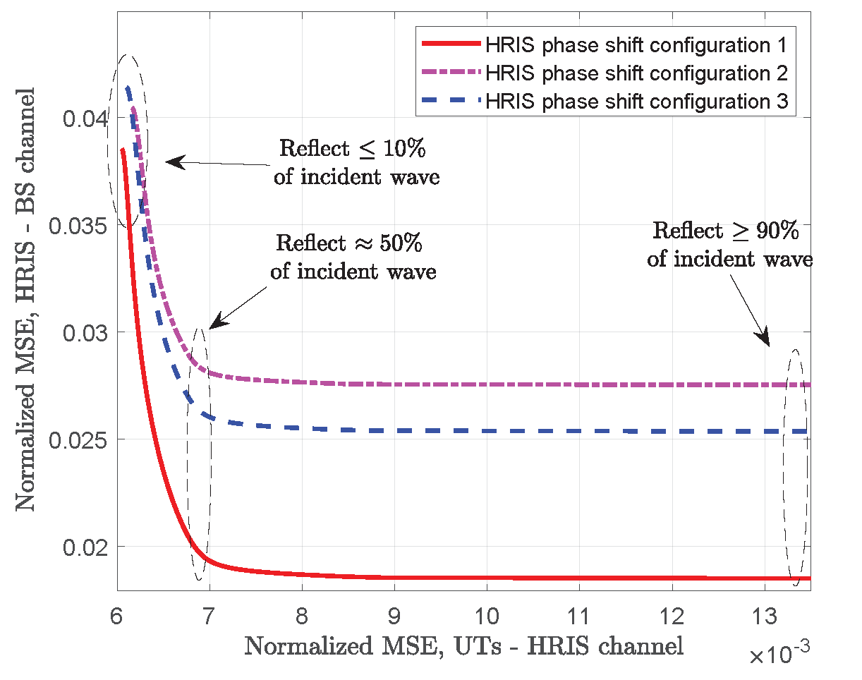
In Fig. 4, we show the trade-off between the normalized MSE performances when estimating the UTs-HRIS channel at the HRIS and the HRIS-BS channel at the BS for different values of the power splitting parameter and dB of transmit SNR. Each curve corresponds to a different random setting of the individual phase shift at each HRIS meta-atom element. As observed, there exists a clear trade-off between the accuracy in estimating each of the individual channels, which is dictated by how the HRIS splits the power of the impinging signal. While the MSE values depend on the HRIS phase configuration, we observe that increasing the portion of the signal that is reflected in the range of up to notably improves the ability to estimate the HRIS-BS channel, while having only a minor effect on the MSE in estimating the UTs-HRIS channel. However, further increasing the amount of power reflected, notably degrades the MSE in estimating the UTs-HRIS channel, while hardly improving the accuracy of the HRIS-BS channel estimation.
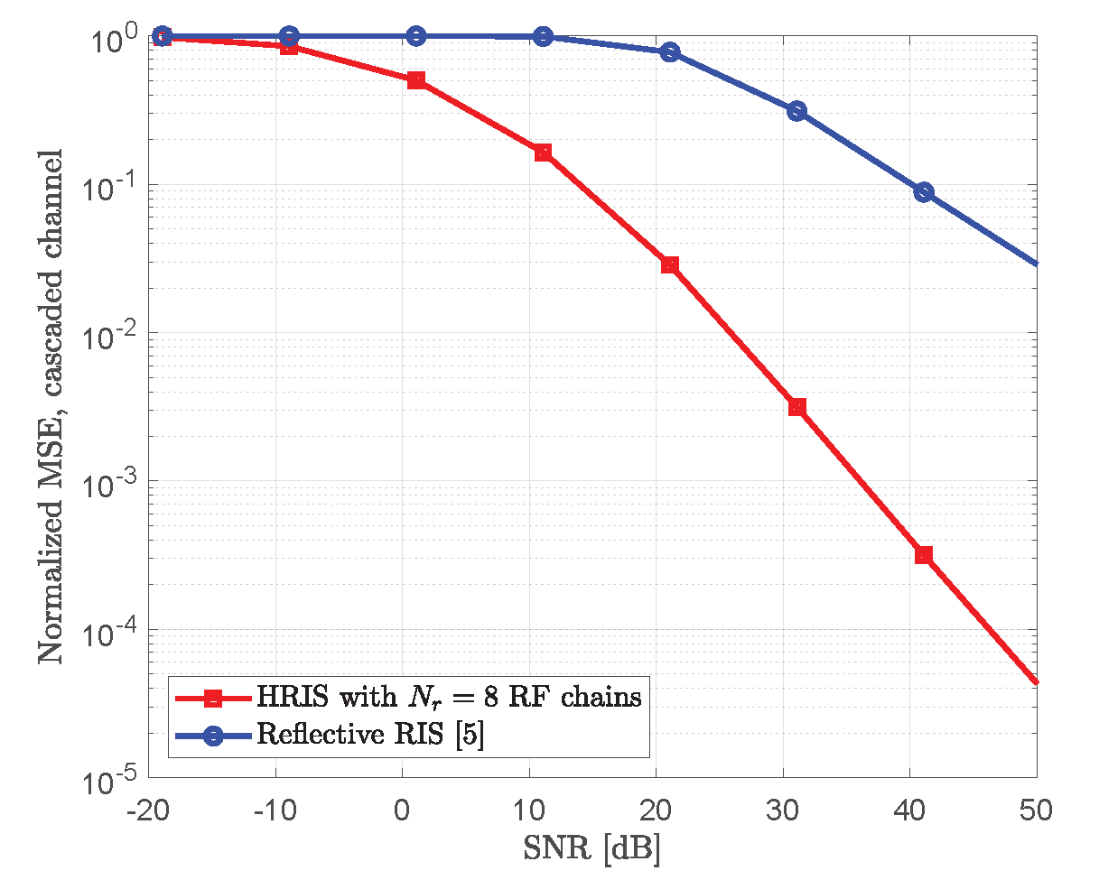
The normalized MSE performance in estimating the cascaded channel for the setup in Fig. 4 with an HRIS, which reflects on average of the received signal, is compared to the method of [5] for reflective RISs in Fig. 5. The cascased channel of our HRIS is calculated based on the individually estimated UTs-HRIS and HRIS-BS channels. The method in [5] requires over pilots, and thus we set the pilot length . As shown in the figure, the HRISs sensing capability is translated into improved cascaded channel estimation accuracy, compared to the state of the art. In particular, the considered HRIS with receive RF chains achieves an SNR gain of over dB, though at the cost of higher power consumption and hardware complexity.
V Conclusions
In this paper, we presented the novel concept of HRISs, which are metasurfaces capable of simultaneously reflecting and sensing impinging signals in a dynamically controllable manner. We presented a simple model for their operation in HRIS-empowered multi-user MIMO communications systems, and investigated their potential to facilitate channel estimation, as an indicative application. We showed that at high SNRs, HRISs enable to significantly save pilot overhead compared to that required by purely reflective RISs. We also quantified the achievable estimation error performance for noisy channels. Our simulation results showcased the impactful role HRISs in RIS-empowered communications in estimating the individual channels as well as the cascaded channel over existing methods relying on nearly passive and reflective RISs.
References
- [1] E. Calvanese Strinati, G. C. Alexandropoulos et al., “Wireless environment as a service enabled by reconfigurable intelligent surfaces: The RISE-6G perspective,” in Proc. Joint EuCNC & 6G Summit, 2021.
- [2] C. Huang, A. Zappone, G. C. Alexandropoulos, M. Debbah, and C. Yuen, “Reconfigurable intelligent surfaces for energy efficiency in wireless communication,” IEEE Trans. Wireless Commun., vol. 18, no. 8, pp. 4157–4170, Aug. 2019.
- [3] Q. Wu and R. Zhang, “Towards smart and reconfigurable environment: Intelligent reflecting surface aided wireless network,” IEEE Commun.Mag., vol. 58, no. 1, pp. 106–112, Jan. 2020.
- [4] C. Huang, S. Hu, G. C. Alexandropoulos, A. Zappone, C. Yuen, R. Zhang, M. Di Renzo, and M. Debbah, “Holographic MIMO surfaces for 6G wireless networks: Opportunities, challenges, and trends,” IEEE Wireless Commun., vol. 27, no. 5, pp. 118–125, Oct. 2020.
- [5] Z. Wang, L. Liu, and S. Cui, “Channel estimation for intelligent reflecting surface assisted multiuser communications: Framework, algorithms, and analysis,” IEEE Transactions on Wireless Communications, vol. 19, no. 10, pp. 6607–6620, 2020.
- [6] H. Liu, X. Yuan, and Y.-J. A. Zhang, “Matrix-calibration-based cascaded channel estimation for reconfigurable intelligent surface assisted multiuser MIMO,” IEEE J. Sel. Areas Commun., vol. 38, no. 11, pp. 2621–2636, Nov. 2020.
- [7] C. Hu, L. Dai, S. Han, and X. Wang, “Two-timescale channel estimation for reconfigurable intelligent surface aided wireless communications,” IEEE Trans. Commun., early access, 2021.
- [8] J. Ye, S. Guo, and M.-S. Alouini, “Joint reflecting and precoding designs for SER minimization in reconfigurable intelligent surfaces assisted MIMO systems,” IEEE Trans. Wireless Commun., vol. 19, no. 8, pp. 5561–5574, Aug. 2020.
- [9] A. Taha, M. Alrabeiah, and A. Alkhateeb, “Enabling large intelligent surfaces with compressive sensing and deep learning,” IEEE Access, vol. 9, pp. 44 304–44 321, 2021.
- [10] G. C. Alexandropoulos and E. Vlachos, “A hardware architecture for reconfigurable intelligent surfaces with minimal active elements for explicit channel estimation,” in Proc. IEEE ICASSP, May 2020.
- [11] N. Shlezinger, G. C. Alexandropoulos, M. F. Imani, Y. C. Eldar, and D. R. Smith, “Dynamic metasurface antennas for 6G extreme massive MIMO communications,” IEEE Wireless Commun., vol. 28, no. 2, pp. 106–113, 2021.
- [12] N. Shlezinger, O. Dicker, Y. C. Eldar, I. Yoo, M. F. Imani, and D. R. Smith, “Dynamic metasurface antennas for uplink massive MIMO systems,” IEEE Trans. Commun., vol. 67, no. 10, pp. 6829–6843, 2019.
- [13] H. Wang, N. Shlezinger, Y. C. Eldar, S. Jin, M. F. Imani, I. Yoo, and D. R. Smith, “Dynamic metasurface antennas for MIMO-OFDM receivers with bit-limited ADCs,” IEEE Trans. Commun., vol. 69, no. 4, pp. 2643–2659, 2020.
- [14] H. Zhang, N. Shlezinger, F. Guidi, D. Dardari, M. F. Imani, and Y. C. Eldar, “Beam focusing for near-field multi-user MIMO communications,” arXiv preprint arXiv:2105.13087, 2021.
- [15] G. C. Alexandropoulos, N. Shlezinger, I. Alamzadeh, M. F. Imani, H. Zhang, and Y. C. Eldar, “Hybrid reconfigurable intelligent metasurfaces: Enabling simultaneous tunable reflections and sensing for 6G wireless communications,” [Online] https://arxiv.org/abs/2104.04690, 2021.