Beam pointing stabilization of an acousto-optic modulator with thermal control
Abstract
Diffraction beams generated by an acousto-optic modulator (AOM) are widely used in various optical experiments, some of which require high angular stability with the temporal modulation of optical power. Usually, it is difficult to realize both angular stability and high-power modulation in a passive setup without a servo system of radio-frequency compensation. Here, we present a method to suppress the angular drift and pointing noise only with the thermal management of the AOM crystal. We analyze the dependence of the angular drift on the refractive index variation, and find that the angular drift is very sensitivity to the temperature gradient which could induce the refractive index gradient inside the AOM crystal. It reminds us such angular drift could be significantly suppressed by carefully overlapping the zero temperature gradient area with the position of the acousto-optic interaction zone. We implement a water-cooling setup, and find that the angular drift of an AOM is reduced over 100 times during the thermal transient, and the angular noise is also suppressed to 1/3 of the non-cooled case. It should be emphasized that this thermal control method is a general to suppress the beam drift in both the diffraction and the perpendicular-to-diffraction directions. The refractive index thermal coefficient of tellurium dioxide crystal at 1064 nm determined by this angular drift-temperature model is 1610-6 K-1 consistent with previous studies. This thermal control technique provides potential applications for optical trapping and remote sensoring that demand for intensity ramps.
1 Introduction
Acousto-optic modulators are widely used to precisely control light intensity and frequency, in which a traveling acoustic wave, generated by a piezoelectric transducer, creates a modulated refractive index and results in the Bragg diffraction of the incoming light [1]. In ultracold gas experiments, AOMs are often applied to tune the light intensity of a high power laser to generate an optical dipole trap (ODT) with time-dependent trap depth for evaporative cooling or parametric cooling [2, 3]. These applications demand for minimizing the pointing noise of the diffracted beam so that the wide-band pointing noise will not parametrically heat ultracold atoms [3, 4]. Meanwhile, slow angular drifting should also be avoided, which causes the instability of optical trapping, especially for a cross-beam ODT [5]. Previously, a large thermal effect on the diffracted beam, induced by radio-frequency (RF) driving, has been observed in many ODT experiments [6, 7, 8, 9]. It has also been verified that the angular drift problem is more serious for the high-power applications, companying with a larger AOM crystal as well as higher RF driving power [6].
There have been several methods to reduce the angular drift, such as keeping the total RF power constant with multiple-frequency components during thermal transient [7, 4], passing AOM twice to cancel out the angular drift [6], RF servo schemes [9, 10] et. al. However, there are still some drawbacks existing in these methods, such as constant RF driving at high power causing the beam shape into elliptical [11], double-passing setup decreasing 25 of the output power. Especially, most of the above methods can not compensate the angular drift along the perpendicular axis of the diffraction direction, for example Piggott detected a 0.1 mrad angular drift of CrystalTech 3080-197 AOM in the vertical direction [8].
In this paper, we theoretically modeled the temperature distribution in the undiffractive direction and measured the refractive index thermal coefficient of tellurium dioxide crystal. We then proposed and demonstrated a method to reduce the angular drift by water-cooling. The angular drift of an AOM has been reduced over 100 times during the thermal transient comparing with the non-cooling case, and the angular noise is also suppressed to 1/3 accordingly. Furthermore, we also find this thermal control method is general to the angular drift suppression in the diffraction direction.
2 Experimental setup and theoretical model

The schematic of the angular drift measurement is shown in Fig. 1a. The separation angle between the zeroth and first order diffracted beams is determined by , where is the wavelength of the incoming light, is the radio-frequency (RF) of the acoustic wave, and is the acoustic-velocity of the medium. The first order diffraction beam is picked and measured by a beam profiler at the far end. The exposure time of the beam profiler is limited to sub-millisecond with the sampling rate of 10 Hz. We fit the beam profile in the horizontal and vertical direction with a 2D Gaussian profile, and use the center of the Gaussian fitting as the beam position . Therefore, it is easy to get X(Y), where X(Y) is the position shift related to the initial position at the far end. The AOM (IntraAction, ATM-804DA6B, tellurium dioxide) has an aperture size of 3 mm. A cartoon structure of the AOM is illustrated in Fig. 1b. AOM is driven by a 80 MHz RF wave along the horizontal direction. The highest diffraction efficiency of the first order is about 92% at 4.5 Watt RF power. The Bragg diffraction angle is around 10 mrad at 1064 nm wavelength. T and T are measured by two thermal couples from 15 to 25 ℃ with 0.1 ℃ precision.
We measured of the AOM caused by thermal transients, as shown in Fig. 2. For a non-cooled AOM, the beam position in vertical direction is slowly drifted to one side in about 10 s. The magnitude of is almost linear proportion to the RF driving power. With the increase of the RF power, T increases slower than T because a copper mount is used in the down side to mount the AOM.
The temperature space-temporal distribution of the AOM crystal can be approximated by a 1D heat diffusion equation [12]
| (1) |
The RF driving generates an uniform energy per unit volume inside the AOM. is the thermal diffusivity, and is the thermal conductivity. When , the system reaches to a steady state. The temperature distribution along the direction is [13]
| (2) |
where is the height of the crystal.
When the RF driving is turned on, the thermal transient inside the crystal can be simplified as
| (3) |
where is the initial temperature difference. The temperature difference affects the refraction of the crystal. The refractive index as a function of radius and time can be obtained from as expressed
| (4) |
where is the refractive index at the initial temperature. This equation assumes a decrease in refractive index with increased temperature.
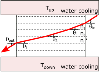
Fig. 3 illustrates the angular drift model for the refraction gradient. We simplify the practical case by assuming 1D temperature gradient, so that , and results in the relation between the input and output angle
| (5) |
With small angle approximation, the angular shift is given by
| (6) |
where is the length of the crystal.
It is notable that we ignore the beam displacement effect at the AOM in Eq. 6. The reason is that, when , the position shift inside the crystal is much smaller than the position shift after the AOM. We confirm this by measuring the angular shift at different values of . The result turns out the beam displacement effect is too small to be considered.
3 Results
3.1 Refractive index thermal coefficient determination
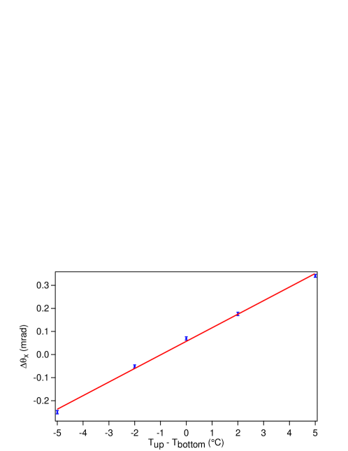
We fix to 20 ℃ and change from 15 to 25 ℃. Then the steady angular drift of the beam is measured with a constant RF power. The result is presented in Fig. 4. The linear dependence of on the temperature difference supports the theoretical model.
In this static measurement, can be ignored. We simulate with Eq. 2, and get , which means the temperature gradient is constant. From Eq. 6, we can easily obtain with at 20 ℃ [14], =20 mm, =6 mm, which is closed to previous results [15].
3.2 Reduce the angular drift
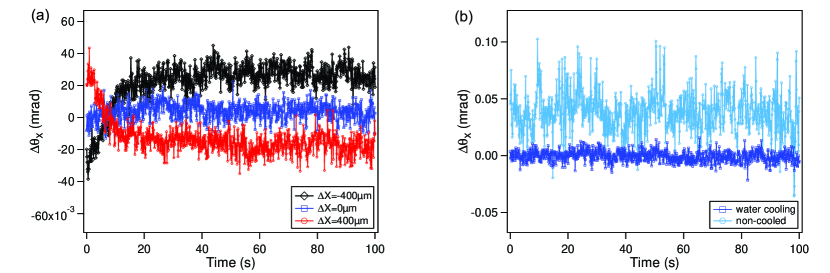
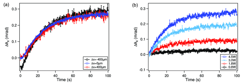
In order to minimize the angular drift of the AOM, we operate the experiments with water cooling, and ℃. From Eq. 2, we can get a parabolic-like temperature distribution with the highest temperature and zero temperature gradient in the middle point, resulting in null in this spot as shown in Fig. 5, the angular shift is reduced from 0.60 mrad to zero mrad level from non-cooling case to cooling-case. From Fig. 5a and Fig. 2a, we can estimate that the magnitude of the refractive index gradient in the middle point is reduced about 10 times by water-cooling. Fig. 5b shows that the water-cooled AOM has 3 times lower angular noise than the non-cooled one, which could be explained by weakening the heating of the crystal [10]. Using the water cooling scheme, our AOM system could be suitable for cooling in micro-ODT [16] and lattice trap [17], both of which highly demand pointing stability and noise reduction.
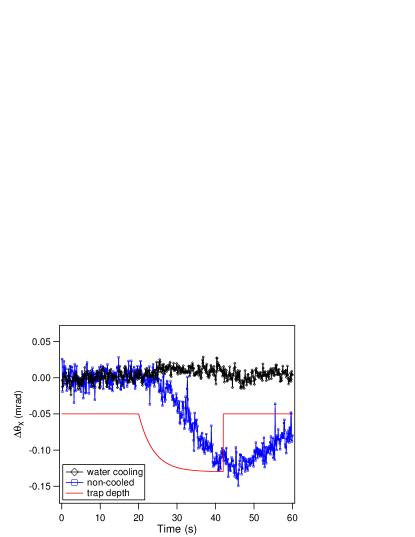
We test the evaporative cooling with the water-cooled AOM [18]. The result is shown in Fig. 6, indicating that the cooling setup could solve the angular drift problem fairly well.
We also use the cooling scheme to suppress the angular drift along the diffraction direction. Different with the perpendicular direction, there is an attached piezoelectric transducer at one side of the diffracting direction, which can not be water-cooled. The solution is that we can control the temperature of the other side to the same temperature as the transducer side by thermal control to make an symmetry temperature distribution along the diffraction direction [6]. The result is shown in Fig. 7.

4 Conclusions
We studied the angular drift and noise of the AOM with RF power ramps. A thermal-control setup is applied to reduce the angular drift significantly as well as the pointing-noise. The results agree with the the refractive index-temperature model of the AOM crystal very well. This technique opens a route for high-precision beam control for laser cooling and trapping with micro-ODT and lattice trap.
Funding
National Natural Science Foundation of China (NSFC) under Grant No.11804406, Fundamental Research Funds for Sun Yat-sen University 18lgpy78. Science and Technology Program of Guangzhou 2019-03-01-05-3001-0035. NSFC No.11774436. SunYat-sen University Discipline Construction Fund, Guangdong ProvinceYouth Talent Program under Grant No.2017GC010656.
References
- [1] I. C. Chang, “I. acoustooptic devices and applications,” \JournalTitleIEEE Transactions on Sonics and Ultrasonics 23, 2–21 (1976).
- [2] R. Grimm, M. Weidemüller, and Y. B. Ovchinnikov, “Optical dipole traps for neutral atoms,” \JournalTitleAdvances In Atomic, Molecular, and Optical Physics 42, 95 – 170 (2000).
- [3] J. Li, J. Liu, W. Xu, L. de Melo, and L. Luo, “Parametric cooling of a degenerate fermi gas in an optical trap,” \JournalTitlePhys. Rev. A 93, 041401 (2016).
- [4] L. Luo, “Entropy and superfluid critical parameters of a strongly interacting fermi gas,” Ph.D. thesis, Duke University (2008).
- [5] C. S. Adams, H. J. Lee, N. Davidson, M. Kasevich, and S. Chu, “Evaporative cooling in a crossed dipole trap,” \JournalTitlePhys. Rev. Lett. 74, 3577–3580 (1995).
- [6] J. Kobayashi, Y. Izumi, M. Kumakura, and Y. Takahashi, “Stable all–optical formation of bose–einstein condensate using pointing–stabilized optical trapping beams,” \JournalTitleApp. Phys. B 83, 21–25 (2006).
- [7] B. Fröhlich, T. Lahaye, B. Kaltenhäuser, H. Kübler, S. Müller, T. Koch, M. Fattori, and T. Pfau, “Two-frequency acousto-optic modulator driver to improve the beam pointing stability during intensity ramps,” \JournalTitleReview of Scientific Instruments 78, 043101 (2007).
- [8] A. Piggot, “Angular drift of crystaltech 3080–197 aoms due to thermal transients,” (2010).
- [9] W. R. Mcgehee, “Transport and disorder-induced localization of unltracold fermi gases,” Ph.D. thesis, University of Illinois at Urbana-Champaign (2015).
- [10] V. I. Balakshy, V. B. Voloshinov, V. A. Karasev, V. Y. Molchanov, and V. Semenkov, “Compensation of thermal effects in acousto-optic deflector,” \JournalTitleProc. SPIE 2713, 164–171 (1996).
- [11] “We measured three aoms, such as intraaction model atm-804da6b, isomet model m1306-t80l-4 and model m1135-t80l-3. all of their diffraction beams become elliptical when the high driving power reaches half of the maximum diffraction efficient,” .
- [12] S. J. Sheldon, L. V. Knight, and J. M. Thorne, “Laser-induced thermal lens effect: a new theoretical model,” \JournalTitleAppl. Opt. 21, 1663–1669 (1982).
- [13] F. P. Incropera, D. P. Dewitt, and T. L. Bergman, Fundamentals of heat and mass transfer (John Wiley Sons, 2007).
- [14] N. Uchida, “Optical properties of single-crystal paratellurite (te),” \JournalTitlePhys. Rev. B 4, 3736–3745 (1971).
- [15] H. Li, J. Lousteau, W. N. MacPherson, X. Jiang, H. T. Bookey, J. S. Barton, A. Jha, and A. K. Kar, “Thermal sensitivity of tellurite and germanate optical fibers,” \JournalTitleOpt. Express 15, 8857–8863 (2007).
- [16] A. N. Wenz, G. Zürn, S. Murmann, I. Brouzos, T. Lompe, and S. Jochim, “From few to many: Observing the formation of a fermi sea one atom at a time,” \JournalTitleScience 342, 457–460 (2013).
- [17] S. Blatt, A. Mazurenko, M. F. Parsons, C. S. Chiu, F. Huber, and M. Greiner, “Low-noise optical lattices for ultracold ,” \JournalTitlePhys. Rev. A 92, 021402 (2015).
- [18] K. M. O’Hara, M. E. Gehm, S. R. Granade, and J. E. Thomas, “Scaling laws for evaporative cooling in time-dependent optical traps,” \JournalTitlePhys. Rev. A 64, 051403 (2001).