ROS georegistration: Aerial Multi-spectral Image Simulator for the Robot Operating System
Abstract
This article describes a software package called ROSgeoregistration intended for use with the Robot Operating System (ROS) and the Gazebo 3D simulation environment. ROSgeoregistration provides tools for the simulation, test and deployment of aerial georegistration algorithms and is made available with a link provided in the paper. A model creation package is provided which downloads multi-spectral images from the Google Earth Engine database and, if necessary, incorporates these images into a single, possibly very large, reference image. Additionally a Gazebo plugin which uses the real-time sensor pose and image formation model to generate simulated imagery using the specified reference image is provided along with related plugins for UAV relevant data. The novelty of this work is threefold: (1) this is the first system to link the massive multi-spectral imaging database of Google’s Earth Engine to the Gazebo simulator, (2) this is the first example of a system that can simulate geospatially and radiometrically accurate imagery from multiple sensor views of the same terrain region, and (3) integration with other UAS tools creates a new holistic UAS simulation environment to support UAS system and subsystem development where real-world testing would generally be prohibitive. Sensed imagery and ground truth registration information is published to client applications which can receive imagery synchronously with telemetry from other payload sensors, e.g., IMU, GPS/GNSS, barometer, and windspeed sensor data. To highlight functionality, we demonstrate ROSgeoregistration for simulating Electro-Optical (EO) and Synthetic Aperture Radar (SAR) image sensors and an example use case for developing and evaluating image-based UAS position feedback, i.e., pose for image-based Guidance Navigation and Control (GNC) applications.
EO-to-EO, EO-to-SAR, Flight Simulation, Georegistration, Image Generation, Robot Operating System (ROS), Vision-Based Navigation.
1 Introduction
Visual sensors have long been used to aid navigation in many autonomous and semi-autonomous flights systems. Concepts like visual odometry [1] and simultaneous localization and mapping (SLAM) [2] can be used to help bound drift inherent in inertial navigation systems [3]. Other more recent approaches such as the multi-state constrained Kalman filter (MSCKF) [4] and pose-graph optimizations as an alternative to filter-based SLAM [5] have been introduced to further improve estimation accuracy, robustness, and/or computational efficiency. Some approaches have leveraged georegistered reference maps and try to match imagery taken in flight to these reference maps to provide the estimator with measurements or factors such as bearings-to-known-features [6] or even direct position updates via sensor pose recovery from corresponding image points [7], or similar. Regardless of the exact approach, there is a long legacy of visual aiding for autonomous navigation that is continuing to expand with machine learning and related developments [8] and an exploration beyond standard electro-optical (EO) and infra red (IR) and into a wide range of sensing modalities including passive millimeter wave [9], synthetic aperture radar (SAR) imaging [10], other RF-based techniques, and more.
This paper presents an academic research and development (R&D) resource which provides a flight environment modeling and simulation (M&S) capability for unmanned aerial systems (UAS) including fixed-wing and multi-rotor systems. Specifically, this work places an emphasis on providing EO and SAR image M&S capabilities to compliment inertial measurement unit (IMU) data and associated truth data to facilitate academic navigation and associated image processing R&D efforts. The intent of this work is to help address the difficulty many researchers face regarding GPS-denied/degraded navigation R&D, namely access to relevant data.
The software packages here provide means to generate the relevant data (images, IMU, truth) for desired flight profiles, assuming a reasonable height above ground. The environment also provides a means to develop and test navigation relevant vision processing concepts while using stand-ins (e.g., UAV and camera truth data) where desired, or to run a complete image-aided navigator pipeline in real-time within the ROS/Gazebo environment, real-time playback, or with non-real-time log files.
The code-base for ROSgeoregistration can be found out: [11] and the authors hope the visual simulation environment, with its tie-ins to effective and efficient vehicle modeling and related simulation capabilities, provides an effective launching point for additional development, both for image processing and navigation within this environment, but also for expanding the underlying simulation capability as well. As an example, the utility of this simulator is demonstrated on SAR and EO georegistration applications and several other potential use cases are highlighted.
The contributions of this work are:
-
1.
Linking the massive multi-spectral imaging database of Google’s Earth Engine to the Gazebo simulator,
-
2.
Simulating geospatially and radiometrically accurate imagery from multiple sensor views for the same terrain region,
-
3.
Integration with other quality UAS tools within a single UAS simulation environment to broadly support UAV and image/signal processing development.
The code used in this paper can be found at: https://github.com/uncc-visionlab/rosgeoregistration.
The rest of the paper is organized as follows: Section 2 describes prior work on simulation environments and related work which can benefit from such tools. Methodology, including integration of core components and new developments, is discussed in section 3. Section 4 provides the results of this work including examples of the data content and imagery produced and example use case. Finally, a conclusion is provided in section 5.
2 Prior and Related Work
This section briefly describes relevant prior work pertaining to simulation for use in image processing development, especially with ties into navigation, and some of the relevant image processing and navigation concepts this simulation environment can help facilitate.
2.1 Vehicle Simulation and Image Generation
A host of prior simulation environments and tools have been made available by the community, however, thorough literature searches found no widely available simulator that integrates flight simulation capability at this level (ROSflight [12], ROSplane [13], ROScopter [14], etc.) with real EO imagery and real SAR measurements.
Some very useful developments provide a ROS environment with reasonable flight dynamics, often for quadrotors [15], some of which have outdoor vision environments [16]. These resources have the advantage of allowing low altitude flight, but are they generally not based on real imagery and would not allow for multi-spectral implementations.
Other vision simulators such as AirSim [17] and WorldWind [18] provide image generation capability. The latter includes camera models leveraging real image data, but has a limited interface and does not appear to have been integrated with ROS vehicle and sensor modeling. The lack of “full stack” vehicle and camera, especially realistic camera data, continues to lead to data set generation [19, 20]. These data sets are highly valuable, especially those with non-simulated data; however the reality is most researchers do not have control over the content, the format, the flight plans, and the data sets are generally fairly limited (by necessity). There is a need for a more customizable, and potentially scalable approach.
To the best of the authors’ knowledge, this is the first “full stack” simulation with real EO imagery and real SAR measurements, especially for the case were realistic models for flight vehicle dynamics, autopilot, and additional sensing (IMU, etc.) is also readily available to support a wide range of developments.
2.2 Image Processing and Navigation
A wide range of image processing capabilities are already available which can used in conjunction with the image generation capabilities provided here. This includes the widely used OpenVC [21] and existing work specifically look at matching EO images to EO satellite data [22], frame to frame feature tracking [23], as well as classic structure from motion [24].
A wide range of past work has looked and image processing to aid navigation [4, 6] and some specifically leveraged ROS and associated simulation capabilities for development prior to hardware implementations [25]. The environment presented in this paper includes highly flexible image model framework, discussed in section 3, and is intended to increase the fidelity of the referenced prior works and allow their expansion to include seasonal variations, multi-spectral matching, e.g., SAR-to-EO [26] or SAR-to-IR [27], and more.
2.3 SAR Simulation Considerations
This simulator provides researchers access to investigate UAS imaging technologies not otherwise possible due to prohibitive SWaP-C (Size, Weight, Power and Cost) requirements. As such, ROSgeoregistration makes it possible for researchers to explore how these data can enhance UAS capabilities and potentially provide insight on how satellite imagery can be used to facilitate UAS applications.
As an example, consider the Sentinel-1 C-band SAR data made available through this effort. In this case, while there has been some work on SAR simulation [28], there is no open-source solutions that enable researchers to generate realistic SAR imagery. Further, federal regulations, platform requirements and the procurement and maintenance costs required to deploy these sensors makes real-world systems prohibitively difficult for most research teams. These barriers to entry discourage SAR image research and slow the development of this technology which shows significant promise for GNC applications since SAR sensors can “see through” clouds, smoke, rain and other atmospheric conditions that block the view of visible light sensors. ROSgeoregistration provides researchers capabilities to leverage SAR data from existing databases and process this data to represent degraded SAR processing due to INS errors which has applications in SAR image formation algorithms for static [29], or moving targets [30] and a wide range of other contexts.
3 Methodology
ROSgeoregistration integrates with existing UAS simulation tools, e.g., ROSflight, ROSplane, ROScopter, to allow a rich variety of sensor fusion applications that may fuse IMU, GPS/GNSS, barometer, and wind-speed sensor data with image registration results. ROSgeoregistration consists of three components/contributions:
-
1.
A Google Earth Engine client to construct multi-spectral terrain models for Gazebo (§ 3.1),
-
2.
A ROS+Gazebo plugin that generates sensor images from the terrain models (§ 3.2),
-
3.
A collection of core components that integrate with the ROS+Gazebo plugin to provide telemetry from other important UAS payload sensors (§ 3.3).
These three components work together in real time to enable a UAS simulation of hypothetical (or real) UAS systems that have sensor imaging capabilities outside (and inside) the visible frequency spectrum, e.g., IR, radio-frequency (RF).
3.1 Google Earth Engine client
The Google Earth Engine client performs a number of tasks that would be time-consuming and prone to error if performed manually. Specifically, it automates the time-consuming process of aggregating and downloading the requested image data, merging image tiles, outputting the required text files and populating these files with the correct information to create a metrically accurate representation of the scene as a Gazebo model. The google earth engine client requires users to specify the following inputs:
-
•
The image data set of interest,
-
•
The location, (latitude,longitude), of the image center and the dimension of the desired image (in meters),
-
•
Any data set search refinement parameters, e.g., cloudy/clear visibility days, time of year, etc.
From these parameters, the Earth Engine client will access Google’s image database system and create the required service requests to obtain the image data and generate the Gazebo model.
Google’s Earth Engine system allows researchers to use software tools to search massive data repositories [31] to make new discoveries. While our discussion is limited to describing multi-spectral applications, we see a wide possibility of applications for the software using alternative data set types. Another desirable aspect of these data are the annotations that add value for selecting specific measurement contexts which allow researchers to find images based on the date/time-of-day (Sentinel 1-3), see table 1, atmospheric conditions, e.g., “cloudy” [32, 33] and many other useful criteria such as quality, time of day, grazing angle, etc., see table 2. Note, each entry from the following tables can be accessed via the Earth Engine website [31] by searching for the associated ‘Name’ entry.
| Name | Wavelengths | Resolution |
|---|---|---|
| skysat | RGB | 0.8m |
| NAIP | RGB | 1.0m |
| landsat-8 | 11 wavelengths | 30m |
| Sentinel-1 | 5.4GHz 4 polarities | 10m |
| Sentinel-2 | 11 wavelengths | 20m |
| Sentinel-3 | 21 wavelengths | 0.0139465 |
Table 1 provides a subset of the multi-spectral image data sources available from Google Earth Engine. Creation of multiple ROSgeoregistration nodes for the same 3D planar model allows researchers to simulate sensing UAS sensor payloads that currently reside only on sophisticated satellite systems. Simulation tools allow researchers to explore the potential classification, navigational and operational capabilities these sensors can provide for more advanced UAS systems.
| Name | Units | Range |
|---|---|---|
| Hourly Surface temp. | Kelvin | 223.6∘- 304∘ |
| Monthly Precipitation | m | 0 - 0.02m |
| Monthly Wind | m/sec | 11.4∘ |
| Vegetation | classes | 584 types |
| Elevation | m | .33 arc seconds |
Table 2 provides a subset of additional image data sources that can also be georegistered and used in conjunction with the aforementioned spectral data. These metadata products could provide key attributes for more reliable recognition or key insights on measurement data to discover unknown correlations between scene reflectance and other phenomena.
3.2 ROS+gazbeo plugin
To maximize the benefit of prior work, ROSgeoregistration, depends on the core ROS UAS simulation tools. Specifically, ROSgeoregistration uses the core as a mechanism to create a vehicle with an arbitrary sensor payload and navigate that vehicle in a simulated 3D environment. ROSgeoregistration then provides additional simulation telemetry that is highly-valuable for conceiving, developing and evaluating algorithms that may seek to leverage recorded sensor image data from the UAS platform for pose or derivative, e.g., velocity or acceleration estimation.
ROSgeoregistration parameters
ROSgeoregistration is a plugin for Gazebo that allows multiple textures to be mapped to a polygonal model within the Gazebo world. Each instance of the plugin creates an application thread, also referred to as a ROS node, that uses the current sensor pose and image formation parameters to generate image telemetry.
Each downloaded terrain model is linked into the Gazebo world (.world file) using an “include” directive to place the model geometry and texture into the 3D Gazebo scene. An instance of the simulation plugin is required to generate a simulated view of the terrain model. Hence, simulation of simultaneous EO, IR, and RF imagery of the terrain requires (3) threads where each thread uses the same model geometry but distinct reference image textures.
Telemetry is generated by finding the projective transformation that maps pixels in the reference image to the pixels of the sensor image. This is accomplished via geometric optics. Specifically, we use the relative geometry of the terrain model and the sensor pose in conjunction with the sensor/camera image formation parameters (aperture, focus, distortion, etc) to determine the world coordinates measured/viewed by the sensor.
Simulating Sensed Images
As with most image sensors, our simulator uses a rectangular image sensor model for image formation whose measurements are recorded on a discrete rectangular grid where each pixel denotes a rectangular cell of this grid. The rectangular sensor geometry imposes a pyramidal view frustum into the simulated 3D environment and our simulator computes the intersection of this view frustum with the 3D planar model containing the reference image data. The intersection locations are used to establish a correspondence, in the form of a projective transformation, between the reference image and the sensed image.
In general, the eight unknown values of the perspective transformation between the reference image and the sensed image require four correspondences between image points and their corresponding locations from the terrain model. The four correspondences are sufficient to solve for the unknowns of the projective transformation by solving a linear system (or by using least-squares when more than four correspondences are provided). This task is common in computer vision image matching applications such as stereo 3D reconstruction. Hence we use the solution to this problem provided by the OpenCV library made available via the cv::getPerspectiveTransform() function.
Sensor-Terrain Model Boundary Conditions
While any four image points will suffice to estimate the perspective transformation, we use the corners of the image to detect when the view of the sensor does not completely fall within the reference terrain model. This can occur when the vehicle flight path causes the sensor view to deviate from the reference image model and typically occurs when the vehicle is not flying over the reference image plane or when vehicle path-following maneuvers, e.g., rolls or pitches, cause the sensor view to exceed the boundary of the terrain reference model. In cases when the entire sensor image cannot be simulated, the simulator does not output image telemetry.
Coordinate Systems
All coordinates from ROSgeoregistration originate from Google Earth Engine. As such, the local world coordinate system is directly linked to standard geospatial coordinate systems, e.g., EPSG:4326 (the Mercator projection) and EPSG:3857 (the Web Mercator projection). With proper parameter specification this allows local values to transfer seamlessly to geospatial coordinate frames, e.g., (latitude, longitude). This is typically easily accomplished by collocating the origin with the center of the georeference source image data.
3.3 Core Components
To deploy ROSgeoregistration, one must first install and configure the simulator “core” dependencies. The ROSgeoregistration packages use the core components to provide real-time simulated sensor image data that is consistent with other simulated vehicle telemetry. This allows the simulated ground truth projective transformations and ground truth sensor poses generated to be fused with other sensor telemetry from the simulated UAS flight. The simulator core components consist of the following ROS packages:
-
•
ROSflight+ROSflight plugins [12]: a suite of ROS packages to allow UAS flight. Plugins add simulated UAS sensor telemetry.
-
•
ROSplane [13]: a suite of ROS packages to allow flight of real or simulated fixed wing aircraft.
-
•
ROScopter [14]: a suite of ROS packages to allow flight of real or simulated multi-rotor drones, e.g., quadcopters.
Collectively the core components allow users to simulate a UAS realized as either a fixed wing or multi-rotor aircraft. The aircraft will be placed in a Gazebo virtual environment which uses the bullet physics engine to simulate standard rigid-body Newtonian forces, e.g., friction, collisions, gravity, inertia, etc. The ROSflight package and, depending on the vehicle, ROSplane or ROScopter packages provide additional forces including lift, wind forces and flight dynamics associated with the chosen vehicle model.
Flight dynamics simulation with ROSflight
The ROSflight software described in [12] provides a suite of ROS packages. For simulation, ROSflight adds forces of flight dynamics into the simulator for both fixed wing aircraft and for muti-rotor drones, e.g., quadcopters. The ROSflight also has plugins that simulate telemetry from important sensors including GPS, airspeed, barometric pressure, an Inertial Measurement Unit (IMU) and a magnetometer. Also included are XML format files (.xacro files) that allow client applications to easily incorporate these sensors into their virtual robot representation by including these sensors in their specific Universal Robot Description File (URDF).
Fixed wing aircraft simulation with ROSplane
The ROSplane ROS package described in [13] provides path planning, path following algorithms and the associated state estimators, e.g., Extended Kalman Filters (EKFs), and controllers required to fly simulated or real fixed wing aircraft. In addition, ROSplane provides enhanced simulation components that incorporate additional forces into the simulation environment and also publish the ground truth state of the fixed wing aircraft.
Quadcopter or drone simulation with ROScopter
The ROScopter ROS package described in [14] provides path planning, path following algorithms and the associated state estimators and controllers required to fly simulated or real multi-rotor aircraft. In addition, ROScopter provides enhanced simulation components that incorporate additional forces into the simulation environment and also publish the ground truth state of the multi-rotor aircraft.
4 Results and Future Work
For results, we describe the new outputs made available by ROSgeoregistration and discuss a use-case experiment where we apply this tool to view a terrain model represented in both the EO (visible light; 400–790 THz) and RF (C-band; 5.4GHz) frequency ranges.
4.1 Experimental Setup
In our example experiment the user wishes to develop, design and evaluate different algorithms for image-based guidance, control and dynamics (GNC) using real-world EO and SAR image data sourced from Google Earth Engine. Generically, a user must complete the steps listed below to run a simulation:
-
1.
Choose a latitude and longitude location of interest and size for the terrain model,
-
2.
Choose the specific Google Earth Engine (or Google Maps) source data and data set parameters for analysis,
-
3.
Use the Google Earth Engine client to locate, download and construct a Gazebo model of the scene as a collection of georeferenced images,
-
4.
For each sensor of each vehicle define the sensor mounting locations and the sensor image formation model,
-
5.
For each vehicle, choose a vehicle a flight path and navigational controller to traverse the path.
-
6.
Run the ROSgeoregistration simulator.
-
7.
Image-based GNC algorithms take in images and compute GNC relevant outputs, e.g., vehicle sensor pose.
In the following paragraphs we detail our path through these steps.
In steps (1,2) we use the UNC Charlotte ECE building roof (35.395703N, -80.535865E) as the UAS launch site and downloaded Google Earth EO satellite data (as provided in Google Maps) and Sentinel-1 SAR data.
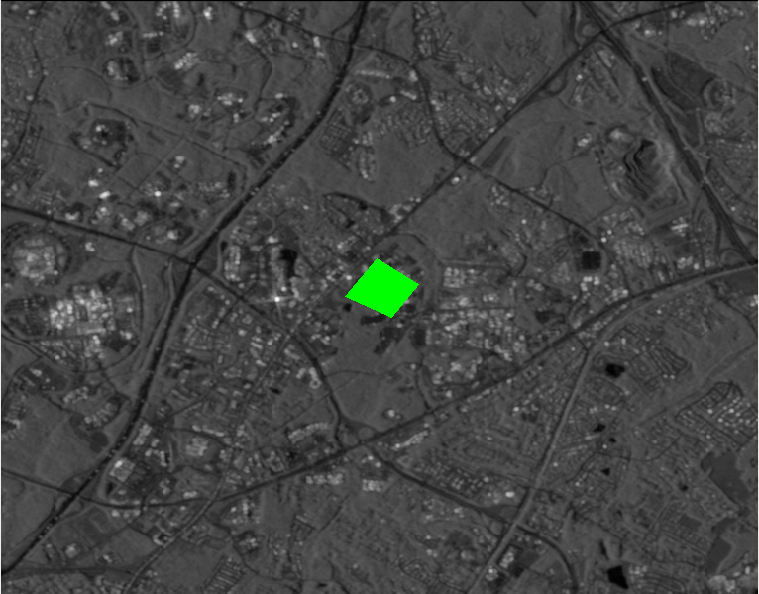
In step (3) the Google Earth Engine client merged EO image from 100 high-quality and unobstructed (not cloudy) EO image tiles to generate a image with resolution of 64006150 pixels spanning a 7643m.7345m. region (1m/pixel resolution). The client extracted Sentinel-1 SAR data (see table 1) for the same region of the Earth’s surface generating a image with resolution 765600 pixels spanning the same region (10m/pixel resolution).
In steps (4,5) we selected a fixed-wing aircraft platform and mounted a virtual downward looking RGB sensor and SAR sensor by modifying the robot URDF. We then used the standard path following controller and path management software from ROSplane to control the flight surfaces and propulsion to traverse a sequence of way-points.
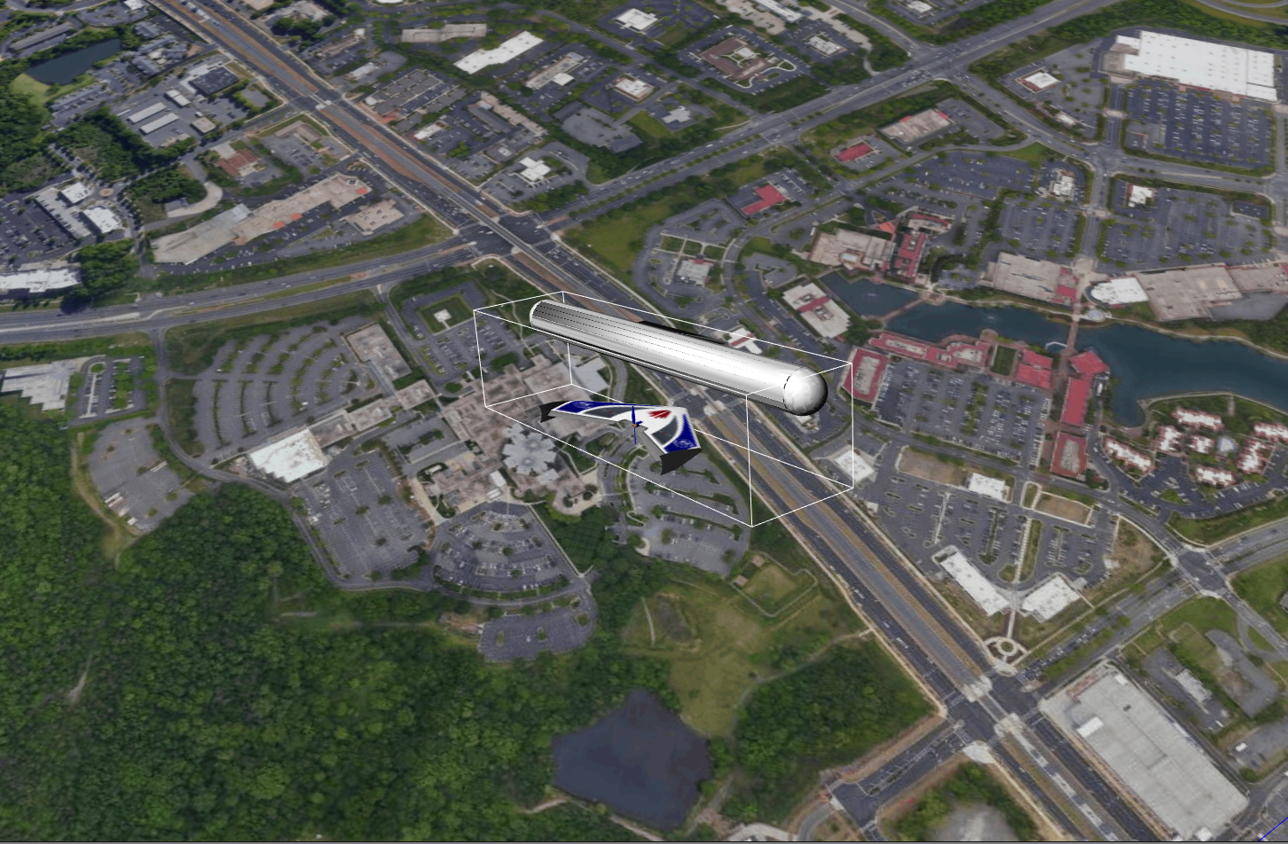
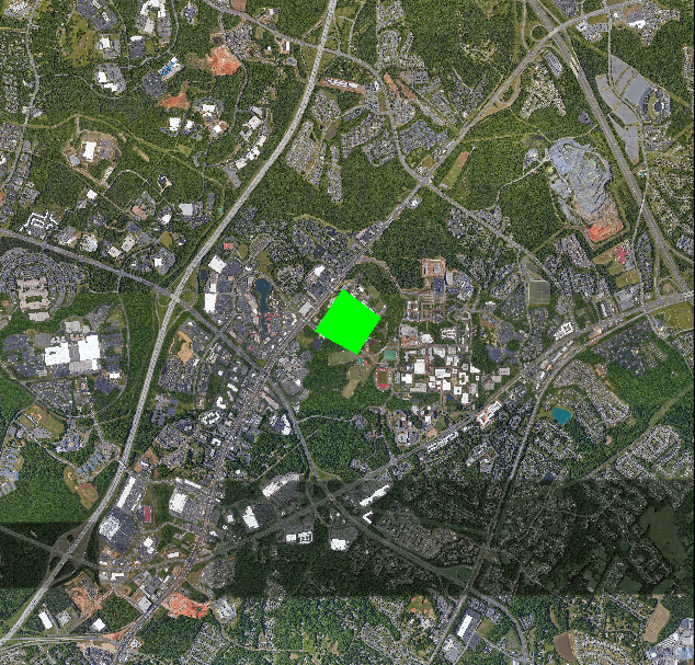
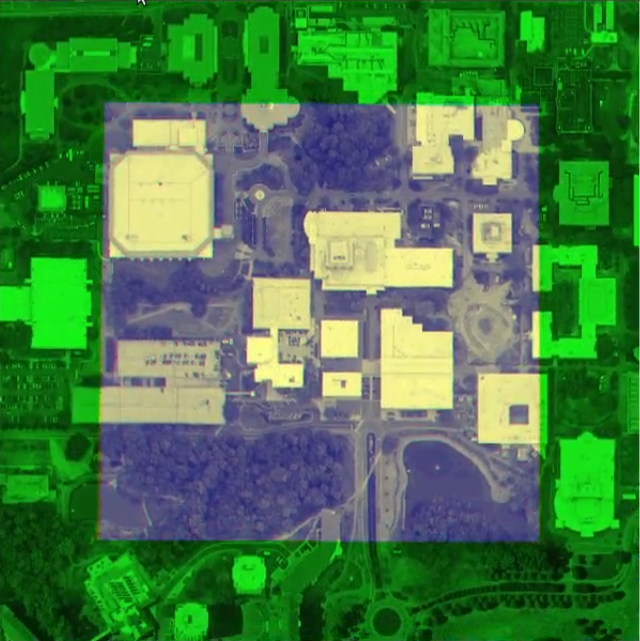
In step (6) we modified the Gazebo world to included the terrain models and added the required “node” elements to the xml of the ROS simulation “launch” file. This file initiates the necessary commands to start the simulation and the ROSgeoregistration plugins to simulate the EO and SAR image data as the vehicle flies through the simulated environment. A rendering of the simulation scene, and one showing the UAV in the Gazebo environment are shown in figure 1. A typical sensor rendering for both EO and SAR are shown in 2.

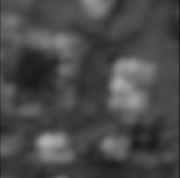
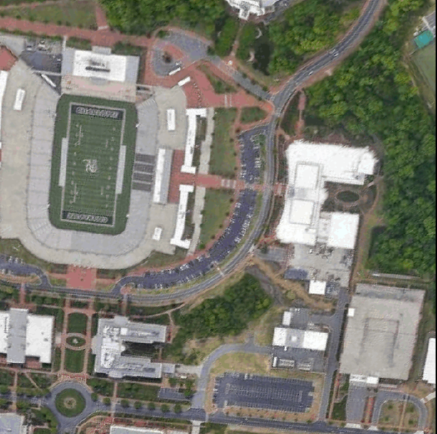
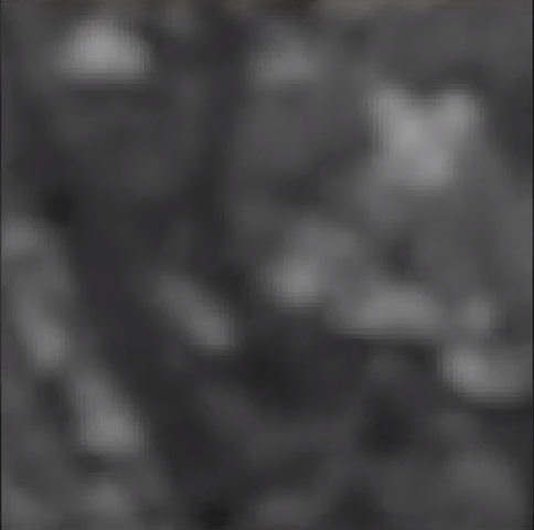
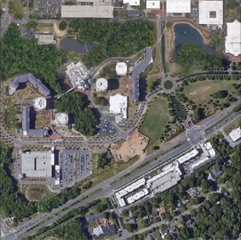
In step (7) we apply the simulated images to evaluate the performance of two image registration algorithms. Fig. 2 shows corresponding views of the same spatial region in the RF band (a) and EO band (b). The stadium and building structures are seen to be in correspondence. Fig. 3(a,b) show image regions extracted from SAR and EO terrain model to generate the images of Fig. 2.
4.2 Example Application
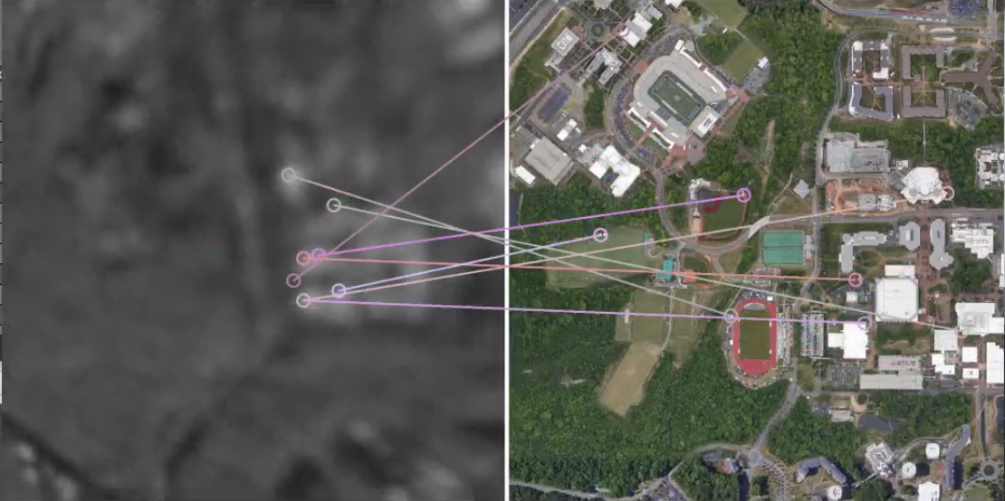
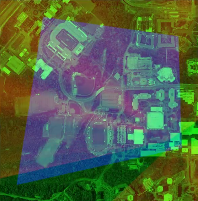
We apply the simulator to evaluate the performance of two registration algorithms: (1) feature-based registration and (2) mutual-information registration. Our application uses these algorithms to match sensed EO and SAR images to a georeferenced EO image stored on the UAS. Registration results can then be used in conjunction with camera calibration parameters to estimate the sensor/vehicle pose (see [7]).
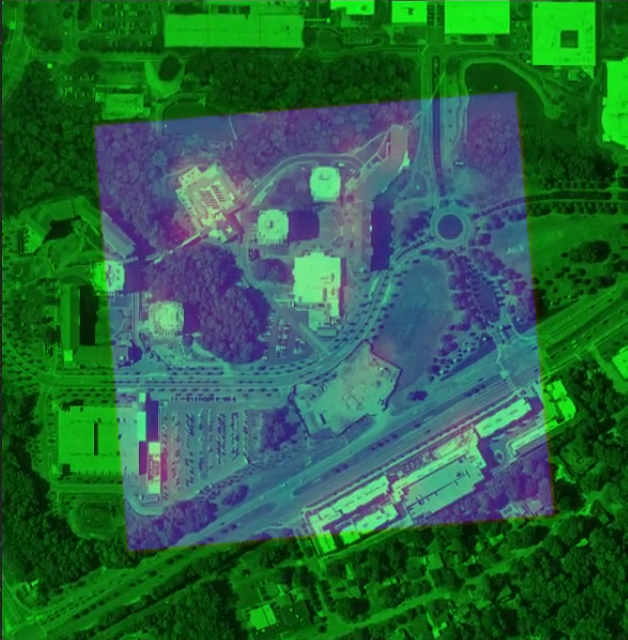
Figure 4 shows homography results where camera/sensor image (left) is matched to a portion of the onboard georeferenced EO image. Effectively the inverse problem of generating the image in the first place, but without access to truth data. In this case, ORB features [34] were matched using RANSAC to find EO-to-EO image correspondences and solve the projective transform that maps pixels of the camera image to the locations in georeferenced EO image [35]. The quality of the solution is depicted as a fused RGB image where the image components are (red=matched intensities sensed EO image, green=georeferenced EO intensities, blue=quadrangular region of the ground truth homography). We find that feature-based matching works well for EO-to-EO imagery having similar scales (see Fig. 4(a,b)). However, this approach fails when used on SAR-to-EO matching problems (see Fig. 4(c,d)). In contrast, the mutual information registration approach is more successful in estimating SAR-to-EO homographies (see Fig. 4(e,f)).

In addition to the simulated image data, the ROSgeoregistration publishes important additional data to client applications to facilitate ground truth based assessment by client applications. This information includes the camera intrinsic parameters, the camera pose, scene footprint (corner) locations of the camera aperture/view, and locations of the footprint within the planar geometry, i.e., analogous to texture coordinates.
4.3 Future Work
One clear drawback of the current approach is the lack of terrain elevation. While this is not a significant concern for many high altitude UAV applications including those likely to leverage SAR as in our example, it does limit the realism for lower altitude flights. Tying vision reference maps into digital terrain elevation data (DTED) would require additional computation when generating camera images, but would result in more realistic view irregularities for camera image to reference map registration.
While the tool currently produces SAR imagery commensurate with a well known trajectory, additional functionality could be added to the SAR image retroactively to approximate effects of navigation error [29], or moving targets [30], as mentioned previously. This manipulation could be done independently to support SAR-to-EO matching, etc., or in-the-loop with image modification being a function of the partnered navigators current state errors.
5 Conclusion
This article introduces a new simulation tool, ROSgeoregistration, to simulate high-altitude, multi-spectral aerial image sensor data. The software represents a novel integration of Google’s Earth Engine with the ROS+Gazebo 3D simulation environment to provide new tools to UAS researchers. Our client to Google Earth Engine greatly reduces the complexity of leveraging the massive multi-spectral imaging database of Google’s Earth Engine to generate terrain models usable by the Gazebo simulator by automatically downloaded the needed data, addressing the coordinate frame transformations, and stitching together image tiles as needed for large reference maps/simulation environments. Our ROS+Gazebo plugin simulates geospatially and radiometrically accurate imagery from multiple sensor views of the same terrain region, and does so accurately, i.e., EO and SAR reference images (and their simulated camera/sensor outputs) are self-consistent. Finally, EO and SAR image generation capabilities were developed to integrate with other ROS vehicle simulation tools provide rich telemetry data, e.g., IMU, GPS, air speed and magnetometer, for data fusion applications. It is hoped that the combination of these tools in one centralized toolkit provides researchers with relevant data for a range of R&D activities including image and multi-spectral processing, navigation, and much more.
6 Acknowledgment
This research is sponsored by an AFRL/National Research Council fellowship and results are made possible by resources made available from AFRL’s Autonomous Vehicles Laboratory at the University of Florida Research Engineering Education Facility (REEF) in Shalimar, FL.
References
- [1] O. Amidi, T. Kanade, and K. Fujita, “A visual odometer for autonomous helicopter flight,” Robotics and Autonomous Systems, vol. 28, no. 2, pp. 185–193, 1999. Intelligent Autonomous Systems (IAS-5).
- [2] M. Bryson and S. Sukkarieh, “Observability analysis and active control for airborne slam,” IEEE Transactions on Aerospace and Electronic Systems, vol. 44, no. 1, pp. 261–280, 2008.
- [3] Z. Wang, W. Wang, C. Hu, X. Si, and J. Li, “A real-time prognostic method for the drift errors in the inertial navigation system by a nonlinear random-coefficient regression model,” Acta Astronautica, vol. 103, pp. 45–54, 2014.
- [4] A. I. Mourikis and S. I. Roumeliotis, “A multi-state constraint kalman filter for vision-aided inertial navigation,” in Proceedings 2007 IEEE International Conference on Robotics and Automation, pp. 3565–3572, 2007.
- [5] F. Youyang, W. Qing, and Y. Gaochao, “Incremental 3-d pose graph optimization for slam algorithm without marginalization,” International Journal of Advanced Robotic Systems, vol. 17, no. 3, 2020.
- [6] M. J. Veth and J. F. Raquet, Image-Aided Navigation - Concepts and Applications, pp. 1571–1595. 2021.
- [7] R. Hartley and A. Zisserman, Multiple View Geometry in Computer Vision. New York, NY, USA: Cambridge University Press, 2 ed., 2003.
- [8] B. S. Chiel and J. Baillieul, “Visual gps-denied multi-agent localization terrain classification,” in 2018 IEEE Aerospace Conference, pp. 1–12, 2018.
- [9] H. Suss, K. Gruner, and W. J. Wilson, “Passive millimeter-wave imaging a tool for remote-sensing,” Alta Frequenza, vol. 58, pp. 457–465, 9 1989. 2nd International Workshop on Millimeter Waves, U. Perugia, Perugia, Italy, April 19-21, 1989.
- [10] O. Montenbruck, R. Kahle, S. D’Amico, and J.-S. Ardaens, “Navigation and Control of the TanDEM-X Formation,” Journal of the Astronautical Sciences, vol. 56, pp. 341–357, 7 2008. Symposium Honoring Byron Tapley’s 50 Years of Contributions.
- [11] “Rosgeoregistration.” github.com/uncc-visionlab/ros_georegistration.
- [12] J. Jackson, G. Ellingson, and T. McLain, “Rosflight: A lightweight, inexpensive mav research and development tool,” in 2016 International Conference on Unmanned Aircraft Systems (ICUAS), pp. 758–762, 2016.
- [13] G. Ellingson and T. McLain, “Rosplane: Fixed-wing autopilot for education and research,” in 2017 International Conference on Unmanned Aircraft Systems (ICUAS), pp. 1503–1507, 2017.
- [14] “Roscopter.” https://github.com/byu-magicc/roscopter. Accessed: 2021-02-20.
- [15] “tum_simulator.” http://wiki.ros.org/tum_simulator. Accessed: 2021-02-20.
- [16] “hector_quadrotor.” http://wiki.ros.org/hector_quadrotor. Accessed: 2021-02-20.
- [17] “Airsim.” https://microsoft.github.io/AirSim/. Accessed: 2021-02-20.
- [18] “Worldwind.” https://worldwind.arc.nasa.gov/java/]. Accessed: 2021-02-20.
- [19] R. Jurevičius and V. Marcinkevičius, “A data set of aerial imagery from robotics simulator for map-based localization systems benchmark,” International Journal of Intelligent Unmanned Systems, vol. 8, pp. 177–186, sep 2019.
- [20] “Ethz data sets.” https://projects.asl.ethz.ch/datasets/doku.php?id=koptinspection:koptinspection. Accessed: 2021-02-20.
- [21] “Opencv.” https://opencv.org/. Accessed: 2021-02-20.
- [22] A. Cesetti, E. Frontoni, A. Mancini, A. Ascani, P. Zingaretti, and S. Longhi, “A visual global positioning system for unmanned aerial vehicles used in photogrammetric applications,” Journal of Intelligent and Robotic Systems, vol. 61, pp. 157–168, 03 2011.
- [23] G. Zhang and P. A. Vela, “Good features to track for visual slam,” in 2015 IEEE Conference on Computer Vision and Pattern Recognition (CVPR), pp. 1373–1382, 2015.
- [24] E. Mouragnon, M. Lhuillier, M. Dhome, F. Dekeyser, and P. Sayd, “Generic and real-time structure from motion,” in British Machine Vision Conference 2007 (BMVC 2007), 2007.
- [25] G. Ellingson, K. Brink, and T. McLain, “Relative navigation of fixed-wing aircraft in gps-denied environments,” Navigation, vol. 67, no. 2, pp. 255–273, 2020.
- [26] S. Paul and U. C. Pati, “High-resolution optical-to-SAR image registration using mutual information and SPSA optimisation,” IET Image Processing, Dec 2020.
- [27] X. Huang, R. Netravali, H. Man, and V. Lawrence, “Multi-Sensor Fusion of Infrared and Electro-Optic Signals for High Resolution Night Images,” Sensors, vol. 12, pp. 10326–10338, Aug 2012.
- [28] S. Auer, R. Bamler, and P. Reinartz, “RaySAR - 3d SAR simulator: Now open source,” in 2016 IEEE International Geoscience and Remote Sensing Symposium (IGARSS), pp. 6730–6733, IEEE, July 2016.
- [29] Y. Li, M. Xing, and Z. Bao, “A new method of motion error extraction from radar raw data for sar motion compensation,” in 2006 CIE International Conference on Radar, pp. 1–4, 2006.
- [30] H. Zhang and R. Yang, “Simulation of multi-channel sar raw data based on real single channel sar data,” in 2006 CIE International Conference on Radar, pp. 1–4, 2006.
- [31] “Earth engine.” https://developers.google.com/earth-engine/datasets/catalog. Accessed: 2021-02-20.
- [32] “landsat-8.” https://developers.google.com/earth-engine/datasets/catalog/landsat-8. Accessed: 2021-02-20.
- [33] “landsat#simple-cloud-score.” https://developers.google.com/earth-engine/guides/landsat#simple-cloud-score. Accessed: 2021-02-20.
- [34] E. Rublee, V. Rabaud, K. Konolige, and G. Bradski, “ORB: An efficient alternative to SIFT or SURF,” in 2011 International Conference on Computer Vision, IEEE, nov 2011.
- [35] A. Goshtasby, 2-D and 3-D image registration for medical, remote sensing, and industrial applications. Hoboken, N.J: John Wiley & Sons, 2005.