Polar Coded Merkle Tree: Improved Detection of Data Availability Attacks in Blockchain Systems
Abstract
Light nodes in blockchain systems are known to be vulnerable to data availability (DA) attacks where they accept an invalid block with unavailable portions. Previous works have used LDPC and 2-D Reed Solomon (2D-RS) codes with Merkle Trees to mitigate DA attacks. While these codes have demonstrated improved performance across a variety of metrics such as DA detection probability, they are difficult to apply to blockchains with large blocks due to generally intractable code guarantees for large codelengths (LDPC), large decoding complexity (2D-RS), or large coding fraud proof sizes (2D-RS). We address these issues by proposing the novel Polar Coded Merkle Tree (PCMT) which is a Merkle Tree built from the encoding graphs of polar codes and a specialized polar code construction called Sampling-Efficient Freezing (SEF). We demonstrate that the PCMT with SEF polar codes performs well in detecting DA attacks for large block sizes.
I Introduction
Decentralization and security properties of blockchains have led to their applications in a wide variety of fields [1, 2, 3, 4, 5, 6, 7]. A blockchain is an immutable ledger of transaction blocks. Full nodes in a blockchain system store the entire ledger and validate transactions. However, for better scalability, blockchains also run light nodes who store the header of each block and cannot validate transactions. Light nodes rely on honest full nodes for fraud proofs [8] in order to reject invalid blocks.
Blockchains where light nodes are connected to a majority of malicious full nodes are vulnerable to data availability (DA) attacks [8, 9]. In this attack, a malicious full node (i.e., an adversary) generates a block with invalid transactions and hides the invalid portion of the block from other nodes. This action prevents honest nodes from sending fraud proofs to the light nodes. Light nodes, in this scenario, randomly request/sample chunks of the block from the block generator and detect a DA attack if any request is rejected. To improve the detection of a DA attack by light nodes, erasure coding has been proposed to encode the block [8] which forces the adversary to hide a larger fraction of the encoded block. However, erasure coding allows the adversary to carry out an incorrect-coding (IC) attack by incorrectly generating the coded block, in which case honest full nodes can send an IC proof to the light nodes to reject the block [8], [9]. Recently, [10] proposed a technique to mitigate DA attacks without requiring IC-proofs, however [10] employs complex cryptographic computations. We remark that channel coding has been considered to mitigate a variety of issues in blockchains [11, 12, 13, 14, 15, 16, 17, 18, 19, 20, 21, 22, 23, 24, 25].
The first paper to address DA attacks via coding used 2D Reed-Solomon (RS) codes to encode each block [8]. Their method was recently optimized in [26]. While offering a high probability of detecting DA attacks, 2D-RS codes result in large IC proof sizes and decoding complexity. Large IC-proof sizes can be exploited by the adversary to congest the network and cause issues such as denial of service attacks, reduced transaction throughput, etc.. To improve upon 2D-RS codes, authors in [9] proposed the Coded Merkle Tree (CMT): a Merkle tree [1] where each layer is encoded using a Low-Density Parity-Check (LDPC) code. LDPC codes reduce the IC proof size compared to 2D-RS codes due to their sparse parity check equations. LDPC codes also allow the use of a low complexity peeling decoder [27] for decoding the CMT where the probability of failure to detect DA attacks depends on the minimum stopping set size of the LDPC code [9].
Application of coding has to be carefully considered depending on the size of the transaction blocks in blockchains which can range from a few MBs (small block size), e.g., Bitcoin [28], Bitcoin Cash[29], to hundreds of MBs (large block size), e.g., Bitcoin SV[30]. For large block sizes, large code lengths are required since large code lengths allow for smaller partitioning of the block, thereby reducing the network bandwidth requirement. In regard to the CMT, previous work in [9] has considered random LDPC codes for large code lengths. However, due to the random construction, the approach has a non-negligible probability of generating bad codes [9] which undermines the security of the system. At the same time, works in [11, 12] have provided deterministic LDPC codes with short code lengths based on the PEG algorithm [31] that result in a low probability of failure. However, the NP-hardness of determining the minimum stopping set size of LDPC codes [32] makes it difficult to provide an efficiently computable guarantee on the probability of failure for large code lengths. As such, designing a CMT with LDPC codes at large code lengths/block sizes is difficult. To mitigate these issues, we propose Polar Coded Merkle Tree (PCMT): a CMT built using the encoding graph of polar codes [33] (we refer to a CMT built using LDPC codes as an LCMT). Although polar codes have dense parity check matrices [34], they have sparse encoding graphs, which result in a small IC proof size in the PCMT. We provide a specialized polar code construction called Sampling-Efficient Freezing (SEF) Algorithm that i) provides a low probability of failure to detect DA attacks; ii) allows flexibility in designing polar codes of any lengths. We demonstrate that SEF Polar codes have an efficiently computable guarantee on the probability of failure which simplifies system design at large block sizes. We then demonstrate that for large block sizes, a PCMT built using SEF Polar codes result in a lower probability of failure compared to LDPC codes designed by the PEG algorithm.
The rest of this paper is organized as follows. In Section II, we provide the preliminaries and the system model. In Section III, we provide our construction method for the PCMT. We present the SEF algorithm in Section IV. Finally, we provide simulation results and performance comparisons in Section V.
II Preliminaries and System Model
Notation: Let and . For a vector , let and denote the th element and th smallest value of , respectively. Let denote the th Kronecker power. Let be the cardinality of set . All logarithms are with base 2. For integers and define , , and , where elements in the three sets are integers.
II-1 Coded Merke Tree preliminaries
A CMT, like a regular Merkle Tree [1], is a cryptographic commitment generator that is used to check the integrity of transactions in the block [9]. Additionally, erasure coding allows to check for data availability via random sampling. In this section, we provide a general framework for the CMT construction that captures its key properties. Later in Section III, we present the PCMT within the general CMT framework.
A CMT parametrized by is a coded version of a Merkle tree [1]. It has layers where is the base layer and is the CMT root. has coded symbols, where . Let be the coded symbols of , where and are the set of data and parity symbols of , respectively. The coded symbols in the CMT are formed as follows: Set the data symbols of the base layer to the chunks of the transaction block. For : a) form the parity symbols from the data symbols using a rate systematic linear code via a procedure ; b) form the data symbols from the coded symbols by a procedure .
The formParent procedure has the property that each data symbol in contains the hashes of coded symbols of . Finally, forms the root Root of the CMT and is the commitment to the block.
Each coded symbol in the CMT has a Merkle proof Proof() which can be used to check the integrity of the symbol given the Root using Verify-Inclusion(, Proof(), Root). The CMT is decoded using a hash-aware decoder which decodes the tree from the root to the base layer. Each layer is decoded using a procedure and the hash of the decoded symbols are matched with their hash provided in the parent layer of the CMT. Assume that the decoded CMT symbols satisfy a degree parity check equation (of the erasure code used for encoding). Of these symbols, if there exists a symbol whose hash does not match with the hash provided by the parent of in the CMT, an IC attack is detected. In this case, an IC proof consists of the following: the symbols and their Merkle proofs, and the Merkle proof of . The IC proof is verified by first verifying that each symbol , , satisfies Verify-Inclusion(, Proof(), Root), then decoding from the remaining symbols (as they form a parity check equation) and then checking that does not satisfy Verify-Inclusion(, Proof(), Root).
We consider a blockchain system similar to [9, 12] with full nodes and light nodes where full nodes produce new blocks. Light nodes only store the CMT root of each block and use it to verify the Merkle proof of CMT symbols and IC proofs. Similar to [8, 9, 11, 12], we assume that light nodes are honest, are connected to at least one honest full node, but can be connected to a majority of malicious full nodes. For the purposes of a DA attack, consider one layer of the CMT having coded symbols. A malicious full node causes a DA attack by a) generating an invalid block and producing its CMT; b) hiding coded symbols (of the coded symbols) such that no honest full node is able to decode back all the coded symbols. Light nodes detect this DA attack by anonymously and randomly requesting (sampling) a small number of coded symbols from the block producer and accepting the block if all the requested samples are returned. A malicious node only returns coded symbols that it has not hidden [8, 9, 11, 12]. Let , which we call the undecodable threshold, be the minimum number of coded symbols that a malicious node must hide to prevent honest full nodes from decoding all the coded symbols. Then, the probability of failure for a light node to detect a DA attack using random i.i.d. samples is . Note that we focus on the security of the system on a per client basis similar to [8],[9]. The following metrics are of importance for a CMT: i) IC proof size (must be small in comparison to the original block size since this proof is communicated to all light nodes and can be used to congest the network), ii) undecodable threshold, iii) complexity of computing the undecodable threshold (which is important at large CMT code length ), and iv) decoding complexity. In this paper, we will demonstrate a construction of CMT using polar codes called the PCMT that performs well on all these metrics when the size of the block is large.
II-2 Polar Codes preliminaries
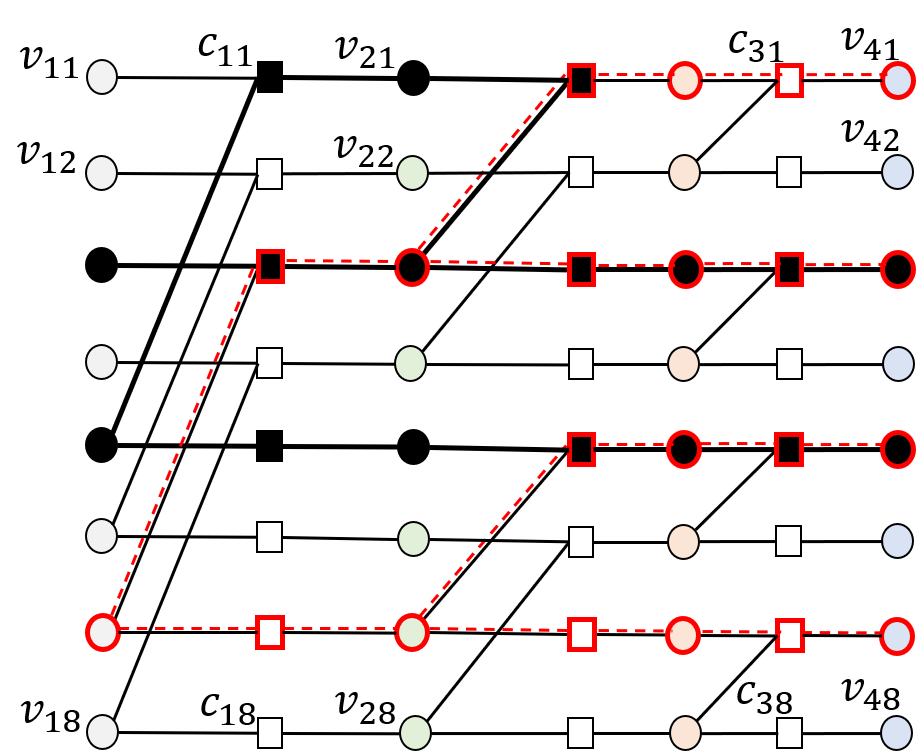
An () polar code of codelength for some integer and information length is defined by a transformation matrix . The generator matrix of the polar code is a submatrix of having of its rows corresponding to the data (information) symbols, while the rest of the rows correspond to frozen symbols (zero chunks in this paper). The factor graph (FG) representation [37] of is shown in Fig. 1 left panel. In general, the FG of (denoted by ) has variable node (VN) and check node (CN) columns. Let () denote the VN (CN) in the th column and th row as shown in Fig. 1. Note that the CNs have a degree of either 2 or 3.
Systematic encoding of polar codes [35, 36] (required for CMT construction), can be performed using the method described in [36]. Given information and frozen index sets and , such that , the systematic encoder of [36] determines the value of all the VNs in the FG such that i) are set to zero (frozen) symbols; ii) VNs in and are the provided data symbols and resultant parity symbols in the systematic encoding. Details regarding systematic encoding can be found in Appendix D.
A polar code can be decoded using a peeling decoder on the code FG. Similar to LDPC codes, the peeling decoder on the FG of a polar code fails if all VNs corresponding to a stopping set (of the FG) are erased. A stopping set is a set of VNs such that every CN connected to this set is connected to at least two VNs in the set. Similar to [37], we call the VNs of a stopping set that are in the rightmost column of the FG as its leaf set denoted by Leaf-Set(). An important category of stopping sets in the FG of polar codes is called stopping trees [37]. A stopping tree is a stopping set that contains only one VN from the leftmost column of the FG (called its root). Fig. 1 left panel shows a general stopping set and a stopping tree in the FG . As demonstrated in [37], each VN , , is root of an unique stopping tree. Let be the unique stopping tree with root VN in the FG and let . It is easy to see (and also proved in [37]) that , , where .
III Polar Coded Merkle Tree (PCMT)
In this section, we describe the construction of a PCMT under the general CMT framework of Section II. Assume all ’s are powers of 2. In Section IV, we remove this assumption. Let () be the information (frozen) index sets of the polar code used in layer of the PCMT. We have and . For convenience, we re-index the row indices in FG such that and are the indices and , respectively.
For the PCMT, define intermediate coded symbols (which are used to form the PCMT) , where , . Index () is the column (row) number of the VN that the symbol corresponds to, in the FG . In the general CMT framework, for , we have , and .
III-1 Formation of PCMT symbols
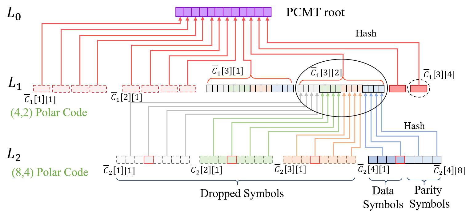
The procedure for a PCMT is as follows: for the data symbols , use a systematic polar encoder as described in Section II to find the parity symbols , where VNs corresponding to in are set as zero chunks. The systematic encoder also provides the set of symbols which are dropped from the PCMT and are not included in . However, before dropping, we use them to form the parent layer in the PCMT. The procedure for a PCMT is as follows. Let and let Hash and concat represent the hash and string concatenation functions, respectively. We have
| (1) | ||||
where . For a PCMT, the root () has a size hashes. In Fig. 2, the formation of is shown.
In the above procedure, data symbols in are formed by taking the hashes of all the intermediate coded symbols of layer (i.e., ) and concatenating hashes together according to Eqn. (1). The intuition behind taking the hashes of all the intermediate coded symbols is so that the symbols in also get committed to the root (i.e., these symbols also have a Merkle proof). Although dropped, the symbols in can be decoded back by a peeling decoder using the available (non-erased) symbols of . Once decoded, they can be used to build small IC proofs using the degree 2 and 3 CNs in the polar FG .
III-2 Merkle proof of PCMT symbols
III-3 Hash-aware peeling decoder and IC proofs
The PCMT is decoded using a hash-aware peeling decoder similar to LCMT in [9]. The procedure for the decoder is as follows. Its acts on the FG . It takes as inputs the frozen symbols and the non hidden symbols of . Using a peeling decoder, it finds all symbols in . The hash of every decoded (peeled) symbol is matched with its hash provided by the parent layer . If hashes do not match, an IC attack is detected. In this case, IC proof is generated using the degree 2 or 3 CN of the FG as per the general CMT framework.
III-A DA attacks on PCMT
Consider layer , , of the PCMT. For a given information index set , let denote the set of all stopping sets in the FG that do not have any VNs corresponding to . The hash-aware peeling decoder fails to decode if coded symbols corresponding to a stopping set in are erased. Since all the coded symbols except the rightmost column of are dropped, the peeling decoder will fail if the adversary hides the leaf set of a stopping set in .
To prevent a DA attack, light nodes randomly sample symbols from the PCMT base layer, i.e., . Randomly sampling the base layer ensures that the non-dropped symbols of intermediate layer , , i.e., , are also randomly sampled via the Merkle proofs of the base layer samples similar to an LCMT in [9]. For subsequent analysis, we assume (WLOG) that the adversary conducts a DA attack on the base layer of the PCMT. To find the adversary strategy that leads to the largest probability of failure when the light nodes use random sampling, we use the following important property of stopping sets in polar FGs that was proved in [37]:
| (3) |
Eqn. (3) implies that, when light nodes use random sampling, the best strategy for the adversary (to maximize the probability of failure) is to hide the smallest leaf set amongst all stopping trees with non frozen root. Thus, .
IV Sampling-Efficient Freezing Algorithm
For the best adversary strategy, . Based on this result, a naïve frozen set selection method would be to select the indices of VNs from the leftmost column of the FG with the smallest stopping tree leaf set sizes . Note that for this naïve frozen set selection, the polar code becomes equivalent to a Reed-Muller (RM) Code [38]. We call the naïve frozen set selection as Naïve-RM (NRM) algorithm for which it can be easily shown that (which is the -th smallest value of ).
Next, we describe the Sampling-Efficient Freezing (SEF) algorithm and show that it results in a higher effective undecodable threshold compared to the NRM algorithm. Additionally, our algorithm allows for polar codes of any length and are not limited to powers of two. Assume that in this section, for all FG , the rows in are indexed to from top to bottom. The SEF algorithm is based on the following lemma.
Lemma 1.
Consider FG where is a power of two. Let and be the frozen and information index sets. For a parameter , define the set of VNs . If , then i) , does not have any VNs in ; ii) all VNs in are zero chunks.
Proof Idea.
Assuming that a stopping set has a VN from , we prove, by incorporating the definition of stopping sets, that , such that . This is a contradiction since and hence does not have VNs in . Full proof can be found in Appendix A. ∎
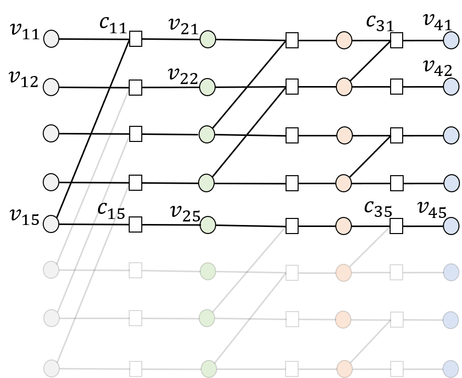
Lemma 1 states that, if the last rows (from the bottom) in the leftmost column of are all frozen, then no stopping set in can have a VN from the last rows in the rightmost column of . Thus, for a frozen index set such that , the light nodes do not need to sample the VNs in . We leverage the above property to improve the effective undecodable threshold of polar codes. Additionally, since all the VNs in , which are all the VNs in the last rows of , are zero chunks, these VNs and their associated edges can be removed from the FG. After this removal, we get the FG of a polar code of length . We use this property to design polar codes of lengths that are not powers of two. An example of FG is shown in Fig. 1 right panel. Algorithm 1 provides the SEF algorithm to design the frozen index set of an polar code; is not necessarily a power of two.
In the SEF algorithm, we first remove the VNs from the last rows in FG (step 3). This gives us the FG which has coded symbols and is used for the construction of the PCMT. Then, in steps 4-7, we select the frozen index set of size for the polar code. Note that (step 4) stores the stopping tree sizes of the VNs , . For the selection of , we first select all the indices in whose corresponding VNs have their stopping tree sizes less than (step 5). Then, the remaining indices in are selected as the VN indices from the bottom row of FG that are not already present in (steps 6-7). We have the following lemma.
Lemma 2.
Let be the largest such that and let . For an polar code produced by the SEF algorithm, let the light nodes randomly sample among the top VNs from the rightmost column of FG . For this sampling strategy, the effective undecodable threshold is . As such, .
Proof Idea.
Note that due to step 5 of the SEF algorithm, . Thus, the undecodable ratio of the SEF algorithm is always as big as the NRM algorithm. The FG output by the SEF algorithm is used for constructing different layers of the PCMT. has VN and CN columns each with VNs or CNs. Thus, for the PCMT construction described in Section III, we replace all instances of with (where ’s need not be powers of two). Rest of the construction remains the same.
| 2D-RS | LCMT | PCMT | ||||
| Root size (KB) | 2.05 | 5.82 | 0.26 | 0.51 | 1.02 | 2.56 |
| IC proof size (MB) | 5.80 | 16.40 | 1.54 | 1.54 | 0.53 | 0.54 |
| Total sample download size (MB) | 10.76 | 12.30 | 43.01 | - | 33.80 | 80.10 |
| Decoding complexity | ||||||
V Simulations and Performance Comparison
In this section, we demonstrate the benefits of a PCMT with respect to the CMT metrics i)-iv) described in Section II when the size of the block is large. We also compare the performance of a PCMT with an LCMT and 2D-RS codes. We denote the output size of the Hash function as and the size of the data chunk (symbol) in the base layer as where block size . We use bits. All PCMTs are built using SEF Polar codes. All LCMTs are built using LDPC codes constructed using the PEG algorithm [31] where the degree of all VNs is set to 3. For the PEG LDPC codes, the undecodable threshold is evaluated by solving an Integer Linear Program (ILP) as described in [39] and is computationally infeasible for larger code lengths. In contrast, SEF Polar codes have an easily computable using Lemma 2. Due to complexity issues, we compute for LDPC codes up to a feasible code length (and, thus, up to a feasible block size). From the description of the PCMT provided in Section III, derivation of its root size, IC proof size, and single sample download size (base layer sample and associated Merkle proof) is straight forward and is provided in Appendix C (which we use to generate the plots in Fig. 3).
In Fig. 3 left panel, we plot the IC proof size vs. block size for an LCMT and a PCMT and different data symbol sizes . We see that for and KB (large block sizes), the IC proof size is smaller for a PCMT compared to an LCMT and gets bigger than an LCMT for KB (small block sizes).
Remark 1.
We note that for a PCMT and an LCMT with the same CMT parameters, the PCMT incurs an asymptotic penalty of in the IC-proof size over the LCMT due to collecting the hashes of VNs in all the columns of the FG (can be seen from the expressions in Appendix C). However for practical block sizes of interest, the IC-proof size of a PCMT can be significantly lower compared to an LCMT, as shown in Fig. 3, due to the low CN degree in the FG of polar codes.
In Fig. 3 middle and right panels, we compare the probability of failure to detect a DA attack conducted on the base layer. We compare for large and short block sizes in the middle and right panels, respectively. From Fig. 3, we see that PCMT has a worse probability of failure compared to an LCMT for small block sizes. However for large block sizes, PCMT always has a lower probability of failure compared to an LCMT across all rates and block sizes thanks to a higher undecodable ratio for the SEF Polar codes and a negligible penalty in the single sample download size.
In Table I, we provide additional comparison of various performance metrics for 2D-RS, LCMT, and PCMT. We can see that PCMT outperforms LCMT w.r.t. IC-proof size and total sample download size with small increase in root size and decoding complexity. While PCMT has a factor greater decoding complexity than an LCMT, the decoding complexity is smaller than for 2D-RS codes which is [9]. At the same time, PCMT also has a lower IC proof size and root size compared to 2D-RS codes while having a higher sample download size. Going from to , the IC-proof size for 2D-RS codes increases 3 fold while the IC-proof size remains almost constant for LCMT and PCMT. Note that for 2D-RS codes, the IC proof size, decoding complexity, and header size do not scale well as the block size increases [9].
Overall, when the size of the transaction block is large, a PCMT built using SEF Polar codes has good performance w.r.t metrics i)-iv) described in Section II and offers a new trade-off in these metrics compared to LCMT and 2D-RS codes.
References
- [1] S. Nakamato, “Bitcoin: A peer to peer electronic cash system," 2008. [Online] Available: https://bitcoin.org/bitcoin.pdf.
- [2] G. Wood, “Ethereum: A secure decentralised generalised transaction ledger," Ethereum project yellow paper, Apr. 2014.
- [3] K. Salah, M. H. U. Rehman, N. Nizamuddin and A. Al-Fuqaha, “Blockchain for AI: Review and open research challenges," IEEE Access, vol. 7, pp. 10127-10149, 2019.
- [4] K. Huang, X. Zhang, Y. Mu, F. Rezaeibagha, X. Du and N. Guizani, “Achieving intelligent trust-layer for internet-of-things via self-redactable blockchain," IEEE Transactions on Industrial Informatics, vol. 16, no. 4, pp. 2677-2686, Apr. 2020.
- [5] M. J. Casey and P. Wong, “Global supply chains are about to get better, thanks to blockchain,” Harvard Business Review, Mar. 2017. [Online] Available: https://hbr.org/2017/03/global-supply-chains-are-about-to-get-better-thanks-to-blockchain.
- [6] N. Teslya and I. Ryabchikov, “Blockchain-based platform architecture for industrial IoT," 21-st Conference of Open Innovations Association (FRUCT), pp. 321-329, Nov. 2017.
- [7] M. Mettler, “Blockchain technology in healthcare: The revolution starts here,” IEEE 18th International Conference on e-Health Networking, Applications, and Services (Healthcom), pp. 1-3, Sept. 2016.
- [8] M. Al-Bassam, A. Sonnino, V. Buterin, “Fraud and data availability proofs: Detecting invalid blocks in light clients," International Conference on Financial Cryptography and Data Security Springer, Mar. 2021.
- [9] M. Yu, S. Sahraei, S. Li, S. Avestimehr, S. Kannan, and P. Viswanath, “Coded merkle tree: Solving data availability attacks in blockchains," International Conference on Financial Cryptography and Data Security, Springer, Cham, pp. 114-134, Feb. 2020.
- [10] K. Nazirkhanova, J. Neu, and D. Tse, “Information dispersal with provable retrievability for rollups," arXiv preprint arXiv:2111.12323 Nov. 2021.
- [11] D. Mitra, L. Tauz, and L. Dolecek, “Concentrated stopping set design for coded merkle tree: Improving security against data availability attacks in blockchain systems," 2020 IEEE Information Theory Workshop (ITW), pp. 1-5, Apr. 2021.
- [12] D. Mitra, L. Tauz, and L. Dolecek, “Overcoming data availability attacks in blockchain systems: LDPC code design for coded merkle tree," arXiv preprint arXiv:2108.13332, Aug. 2021.
- [13] S. Cao, S. Kadhe, and K. Ramchandran, “CoVer: Collaborative light-node-only verification and data availability for blockchains," IEEE International Conference on Blockchain (Blockchain), pp. 45-52, Nov. 2020.
- [14] D. Perard, J. Lacan, Y. Bachy, and J. Detchart, “Erasure code-based low storage blockchain node," IEEE International Conference on Internet of Things (iThings) and IEEE Green Computing and Communications (GreenCom) and IEEE Cyber, Physical and Social Computing (CPSCom) and IEEE Smart Data (SmartData), pp. 1622-1627, Jul. 2018.
- [15] M. Dai, S. Zhang, H. Wang, and S. Jin, “A low storage room requirement framework for distributed ledger in blockchain," IEEE Access, vol. 6, pp. 22970-22975, Mar. 2018.
- [16] Q. Huang, L. Quan, and S. Zhang, “Downsampling and transparent coding for blockchain" arXiv preprint arXiv:1911.01778, Nov. 2019.
- [17] D. Mitra and L. Dolecek, “Patterned erasure correcting codes for low storage-overhead blockchain systems,” IEEE Asilomar Conference on Signals, Systems, and Computers, pp. 1734-1738, Nov. 2019.
- [18] S. Kadhe, J. Chung, and K. Ramchandran, “SeF: A secure fountain architecture for slashing storage costs in blockchains," arXiv preprint arXiv:1906.12140, Jun. 2019.
- [19] A. Tiwari, and V. Lalitha, “Secure raptor encoder and decoder for low storage blockchain," International Conference on COMmunication Systems & NETworkS (COMSNETS), pp. 161-165, Jan. 2021.
- [20] D. S. Gadiraju, V. Lalitha, and V. Aggarwal, “Secure regenerating codes for reducing storage and bootstrap costs in sharded blockchains," IEEE International Conference on Blockchain (Blockchain), pp. 229-236, Nov. 2020.
- [21] B. Choi, J. Sohn, D. Han, and J. Moon, “Scalable network-coded PBFT consensus algorithm," IEEE International Symposium on Information Theory (ISIT), pp. 857-861, Jul. 2019.
- [22] S. Li, M. Yu, C. Yang, A. S. Avestimehr, S. Kannan, and P. Viswanath, “PolyShard: Coded sharding achieves linearly scaling efficiency and security simultaneously," IEEE Transactions on Information Forensics and Security, vol. 16, Jul. 2020.
- [23] C. Wang, and N. Raviv, “Low latency cross-shard transactions in coded blockchain," arXiv preprint arXiv:2011.00087, Oct. 2020.
- [24] P. Sheng, B. Xue, S. Kannan, and P. Viswanath, “ACeD: Scalable data availability oracle," arXiv preprint arXiv:2011.00102, Oct. 2020.
- [25] D. Mitra, L. Tauz, and L. Dolecek, “Communication-efficient LDPC code design for data availability oracle in side blockchains," IEEE Information Theory Workshop (ITW), pp. 1-6, May 2021.
- [26] P. Santini,G. Rafaiani, M. Battaglioni, F. Chiaraluce, M. Baldi, et al., “Optimization of a Reed-Solomon code-based protocol against blockchain data availability attacks", arXiv preprint arXiv:2201.08261v1, Jan. 2022.
- [27] T. Richardson, and R. Urbanke, “Modern coding theory," Cambridge: Cambridge University Press, 2008.
- [28] Online: https://www.blockchain.com/charts/avg-block-size, accessed 11th Jan. 2022.
- [29] Online: https://bitinfocharts.com/comparison/bitcoin%20cash-size.html#3y, accessed 11th Jan. 2022.
- [30] Online: https://bitinfocharts.com/comparison/bitcoin%20sv-size.html#3y, accessed 11th Jan. 2022.
- [31] X.Y. Hu, E. Eleftheriou and D.M. Arnold, “Regular and irregular progressive edge-growth tanner graphs," IEEE Transactions on Information Theory, vol. 51, no. 1, pp. 386-398, Jan. 2005.
- [32] K. M. Krishnan, and P. Shankar, “Computing the stopping distance of a Tanner graph is NP-hard," IEEE Transactions on Information Theory, vol. 53, no. 6, pp. 2278-2280, Jun. 2007.
- [33] E. Arikan, “Channel polarization: A method for constructing capacity-achieving codes for symmetric binary-input memoryless channels,” IEEE Transactions on Information Theory, vol. 55, no. 7, pp. 3051-3073, Jul. 2009.
- [34] N. Goela, S. B. Korada, and M. Gastpar, “On LP decoding of polar codes," IEEE Information Theory Workshop, pp. 1-5, Aug. 2010.
- [35] E. Arikan, “Systematic polar coding," IEEE Communications Letters vol. 15, no. 8, pp. 860-862, Aug. 2011.
- [36] L. Li and W. Zhang, “On the encoding complexity of systematic polar codes," IEEE International System-on-Chip Conference (SOCC), pp. 415-420, Sept. 2015.
- [37] A. Eslami, H. Pishro-Nik, “On finite-length performance of polar codes: stopping sets, error floor, and concatenated design," IEEE Transactions on Communications, vol. 61, no. 3, pp. 919-929, Feb. 2013.
- [38] D. E. Muller, “Application of boolean algebra to switching circuit design and to error correction,” Transactions of the I.R.E. Professional Group on Electronic Computers, vol. EC-3, no. 3, pp. 6–12, Sept. 1954.
- [39] A. Sarıduman, A. E. Pusane, Z. C. Taşkın, “An integer programming-based search technique for error-prone structures of LDPC codes," AEU-Int. Journal of Electronics and Communications, vol. 8, no. 11, pp. 1097-1105, Nov. 2014.
Appendix A Proof of Lemma 1
First of all, it is easy to see that when all the VNs in (i.e., the VNs in the last rows from the leftmost column of FG ) are frozen or set to zero chunks, all the VNs in the last rows from all the columns will be zero chunks. This is because every CN in row of the FG is either connected to VNs in the same row or to VNs from a row below (i.e., having a row index greater than ) in the FG. This proves the second claim of the lemma.
For the first claim, let and let be the induced subgraph of corresponding to the set of VNs . From the definition of , does not have any frozen VNs from the leftmost column of the FG , i.e., does not have any VNs in the set . Since , does not have any VNs in .
We prove the first claim of the lemma by contradiction. Assume that has a VN from . In particular, assume that , where and . Now, by the property of stopping sets, . Now, to satisfy the stopping set property, either or where and and are connected in . Thus, for the column number , we have at least one index , such that . Proceeding in a similar manner as above, for the column number , we have at least one index , such that . Repeating the same process until we reach the leftmost column, we can find at least one index , such that . However, this is a contradiction of the fact that does not have any VNs in set .
Appendix B Proof of Lemma 2
The SEF algorithm produces a polar code with a FG where the bottom VNs from the leftmost column of are frozen. Moreover, is obtained from freezing (and hence removing) the last rows of , where . Note that is the output of the SEF algorithm and . Define , . Clearly, and are the same sets. Thus, the polar code can be seen as a code defined on the FG with frozen index set , and information index set , where only the top VNs from the rightmost column of are the coded symbols.
Due to Lemma 1, VNs in the last rows in the rightmost column of are not part of any stopping set in . This implies that VNs in the last rows in the rightmost column of are not part of any stopping set in . Thus in the FG , the light nodes do not need to sample the VNs in the last rows in the rightmost column of and only randomly sample the top VNs. Moreover, from Eqn. (3) (applied on FG ), the smallest leaf set size of all stopping sets in is given by
Hence, the probability of failure resulting in an effective undecodable threshold of .
| 2D-RS | LCMT | PCMT | |
|---|---|---|---|
| Root size | |||
| Single sample download size | |||
| IC proof size | |||
| Decoding complexity | |||
| Analytical expression in [8] | NP-hard to compute | Lemma 2 |
Appendix C Performance Analysis and Comparison
Comparison of various performance metrics of an LCMT, a PCMT and 2D-RS codes is provided in Table I. The metrics for 2D-RS codes are calculated as described in [8]. Detailed derivation of the root size, single sample download size, and IC proof size for an LCMT and PCMT in Table I is as follows.
C-1 Root size
For an LCMT, the root consists of the hashes of all the coded symbols in . Hence, the root consists of hashes and, thus, has a size of . For a PCMT, the root consists of hashes of all the coded and dropped symbols in , i.e., the hashes of all the VNs in FG of the polar code used in . Hence, the root consists of hashes and, thus, has a size of .
C-2 Single sample download size
For an LCMT, as described in [9, 24, 12], each sample request consists of a base layer symbol of the CMT and the Merkle proof of the base layer symbol. Moreover, the Merkle proof of the base layer symbol consists of a data symbol and a parity symbol from each layer above the base layer (i.e., layers , ). The Merkle proof satisfies the property that the data symbol in proof from layer consists of the hash of the data symbol in proof from layer , . Thus, of the hashes present in the data symbol of the Merkle proof from layer , , the hash corresponding to the data symbol of the Merkle proof from layer is not communicated in the Merkle proof (and it can be calculated by taking a hash of the data symbol of the Merkle proof from layer ). Thus, there are only hashes from each layer , for the data part in the Merkle proofs. Thus, the size of the Merkle proof of a base layer symbol is (since the size of each parity symbol is ). Finally, the overall download size for a single sample request is , where is the size of the base layer symbol.
For a PCMT, similar to an LCMT above, a sample request consists of a base layer symbol of the PCMT and the Merkle proof of the base layer symbol. The Merkle proof of the base layer symbol in this case again consists of a data symbol and a parity symbol from each layer above the base layer. Note that, here, the data and the parity symbols in layer are the non-dropped symbols of the polar FG corresponding to the information and frozen set indices, respectively. In contrast to an LCMT, in a PCMT, each data symbol of layer , consists of hashes.
The Merkle proof in a PCMT also satisfies the property that the data symbol in proof from layer consists of the hash of the data symbol in proof from layer , . Thus, only hashes from layers , are present in the data part of the Merkle proofs. Thus, for a PCMT, the size of the Merkle proof of a base layer symbol is
Finally, the overall download size for a single sample request is , where is the size of the base layer symbol in a PCMT. Note the additional penalty factor of in the single sample download size for a PCMT compared to an LCMT. However, for large block sizes when is large compared to , the penalty is small.
C-3 IC proof size
As described in Section II, the IC proof for a failed parity check equation with symbols consists of symbols and the Merkle proofs of the symbols. Note that the proof size is largest for a failed parity check equation in the base layer. Thus, we provide the IC proof size when the symbols are base layer symbols. Also note that, in IC proofs, the Merkle proof of a symbol only consists on the data symbols from each layer above the base layer (the parity symbols included in the Merkle proofs of the light node samples are only to get additional samples of the intermediate layers) [9, 24]. Thus, in an LCMT, for a failed parity check equation with symbols, the size of the IC proof is , where the term arises due to the same reason as explained in the single sample download size calculation. Hence, when the maximum CN degree of the LDPC code is , the IC proof size becomes .
For a PCMT, the IC proof for a failed parity check equation with symbols again consists of symbols and the Merkle proofs of the symbols. Note that the symbols here can be both the dropped or non-dropped symbols of the polar FG. Also, each data symbol of layer , in a PCMT consists of hashes. Thus, for a failed parity check equation with symbols, the size of the IC proof in a PCMT is
For a PCMT, the maximum CN degree for a CN in the FG of the polar code is . In this case, the IC proof size becomes .
C-A Undecodable Threshold
The undecodable threshold for an LCMT with the LDPC codes described in Section V and a PCMT with SEF Polar codes is shown in Fig. 4. From the figure, we see that a PCMT has a higher compared to an LCMT for different values of rates and code lengths . Hence for large block size , when the penalty in the single sample download size for a PCMT is small, they have a lower probability of failure compared to an LCMT for the same total sample download size. This result is shown in Fig. 3 right panel.
Appendix D Systematic encoding of Polar codes
Systematic encoding of an polar codes can be performed using the method described in [36]. It operates on the FG of the code. Let and be the index sets corresponding to the data and frozen symbols of the polar code, respectively, where . Also, let . The systematic encoding is performed on the FG by i) placing the data symbols at the VNs (in the rightmost column) and setting the VNs at (in leftmost column) to zero symbols; ii) determining the rest of the VNs using the check constraints of the FG in a two stage reverse and forward encoding on the FG [36]. The coded symbols are the VNs and are by design systematic. Systematic encoding can also be performed using a peeling decoder as the encoder as described next.
In [35], author proposed to perform systematic encoding of polar codes by using a successive cancellation decoder on the code FG as the encoder. Inspired by this idea, we show that systematic encoding of the polar codes can also be performed using a peeling decoder as the encoder. The encoder, which we call a peeling encoder for polar codes (PEPC), works as follows. Consider the data and frozen index sets and of the polar code with FG . Place the data symbols at the VNs (in the rightmost column) and set the VNs at (in leftmost column) to zero symbols. Use a peeling decoder to find the remaining VNs of the FG. The coded symbols are by design systematic. We have the following lemma corresponding to a PEPC.
Lemma 3.
Systematic encoding of polar codes using a PEPC always results in a valid codeword. In other words, the peeling decoder never encounters a decoding failure when used for encoding.
We prove Lemma 3 by proving the following important property of stopping sets in the FG of polar codes produced by the SEF algorithm. Note that the property holds true for regular polar FG where is a power of 2. Additionally, the property also holds true for the FG obtained by removing VNs from the last few rows of FG of the form , where is a power of 2. Thus, let . The proof provides insights on important properties of stopping sets in the FG of polar codes. To our best knowledge, we have not seen the following result before in literature and, hence, it may be of independent interest.
Lemma 4.
Consider a polar FG produced by the SEF algorithm (this encompasses polar factor graphs , where is a power of 2). Every stopping set of has a full row of VNs i.e., it has all VNs in the set for some .
Proof.
Let be a stopping set of . Let be the induced subgraph of corresponding to the set of VNs . Observe that the FG has two types of edges (see Fig. 1 for an example): horizontal edges and slanted edges (which involves a connection between a degree 3 VN and a degree 3 CN). We consider two cases: i) does not have any slanted edges; ii) has at least one slanted edge.
For case i), it is easy to see that the stopping set must include a full row of VNs. For case ii), note that it implies has at least one slanted edge. This implies that has at least one VN of degree 3. In this situation, define the set . Let . contains the indices of all the degree 3 VNs of and denotes the largest row index such that has a degree 3 VN from that row. Note that is non empty because we are considering case ii). Now, we claim that has all the VNs in the row , i.e., contains all the VNs in . To see why this is true, let , , be such that . This means that . Now by the definition of a stopping set, the CNs to the right and left of must belong to the induced subgraph graph of the stopping set. In other words, and (unless is the rightmost or the left most VN in which case we will have only one CN neighbour). Now, to satisfy the stopping set property, for both these CNs, their corresponding VNs to their left and right in the same row must belong to the stopping set (i.e., , ). If not, then to satisfy the stopping set property, the CN must be connected to a VN by a slanted edge. Note that a slanted edge connects a CN to a degree 3 VN in lower row. In other words, a slanted edge connects a CN from row to a degree 3 VN in a row with index greater than . This condition violates the definition of . Thus, and . Now, considering and as the starting VN (similar to ), we can apply the above logic to show that and . Repeatedly applying the same argument, we can show that all the VNs in belong to , where .
∎
According to the above lemma, every stopping set has at least one full row of VNs, i.e., it has VNs from all columns along a single row. We use this property to prove Lemma 3.
Proof of Lemma 3:
Let be the set of all VNs in the polar FG . Also, let and . VNs in are uninitialized or initially erased by the PEPC and are determined using a peeling decoder (for the purposes of encoding).
Thus, the PEPC can fail if contains a stopping set of . However, since (i.e., they form a partition of all the row indices), for all either or . Thus, for all , and both cannot simultaneously belong to . Hence, cannot contain a full row of VNs. Using Lemma 4, we conclude that cannot contain a stopping set. Thus, the PEPC will always be successful and will result in a valid codeword.