Self phase-matched broadband amplification with a left-handed Josephson transmission line
Abstract
Josephson Traveling Wave Parametric Amplifiers (J-TWPAs) are promising platforms for realizing broadband quantum-limited amplification of microwave signals. However, substantial gain in such systems is attainable only when strict constraints on phase matching of the signal, idler, and pump waves are satisfied – this is rendered particularly challenging in the presence of nonlinear effects, such as self- and cross-phase modulation, which scale with the intensity of propagating signals. In this work, we present a simple J-TWPA based on ‘left-handed’ (negative-index) nonlinear Josephson metamaterial, which has phase matching native to its design, precluding the need for any complicated circuit or dispersion engineering. The resultant efficiency of four-wave mixing process can implement gains in excess of 20 dB over few GHz bandwidths with much shorter lines than previous implementations. Furthermore, the intrinsic phase matching considerably simplifies the J-TWPA design and operation compared to the previous implementations based on ‘right-handed’ (positive index) Josephson metamaterials, making the proposed architecture particularly appealing for integration with large superconducting architectures. The left-handed JTL introduced here constitutes a new modality in distributed Josephson circuits, and forms a crucial piece of the unified framework that can be used to inform the optimal design and operation of broadband microwave amplifiers.
I Introduction
Josephson Parametric Amplifiers (JPA) are a key element for high-fidelity microwave signal processing, [1, 2, 3, 4] enabling applications ranging from qubit readout [5], real-time quantum feedback, quantum metrology [6, 7] to quantum sensing. Conventional JPA designs, based on Josephson junction(s) integrated in a resonant circuit, realize standing wave amplification at a fixed frequency; while ease of design of such amplifiers have made them a standard functionality in microwave measurements, such lumped-element designs are typically limited to relatively small instantaneous bandwidths and dynamic range (input signal powers for which amplification remains linear). There have been numerous proposals in recent years based on impedance engineering [8, 9], nonlinearity engineering [10, 11] and coherent feedback via auxiliary modes [12, 13] that can partially alleviate this issue; however, the ultimate amplification bandwidth, and concomitant saturation input powers, in such modified-JPA designs are still limited by the bare resonance linewidth of the signal mode.
A compelling alternative to standing-wave JPAs are Josephson Traveling Wave Parametric Amplifiers (J-TWPA) [see [14] and references therein] that incorporate Josephson nonlinearity in a waveguide or transmission-line geometry. Unlike the lumped-element JPA circuits, the distributed nonlinearity of J-TWPA involves no resonating structures and thus, in principle, realizes much larger gain-bandwidth products. In addition to realizing broadband gain, TWPAs have the desirable property of unilateral amplification since only signals co-propagating (and hence phase matched) with the pump waves are amplified efficiently. This allows TWPAs to implement a natural separation of input and output channels, without involving any channel separation devices such as circulators or isolators that rely on external magnetic fields. Owing to this amenability and potential promise for integrated and scalable multiplexing, several theoretical and experimental approaches for realizing high-efficiency J-TWPAs have been explored, with the primary candidates being (i) engineered metamaterials based on arrays of Josephson junctions [15, 16, 17, 18, 19, 20, 21], and (ii) nonlinear materials utilizing kinetic inductance of superconducting nanowires [22, 23, 24, 25, 26, 27].
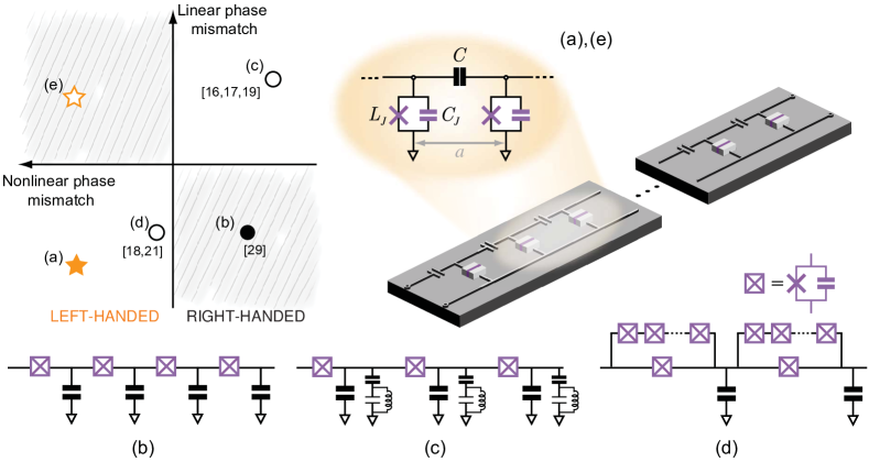
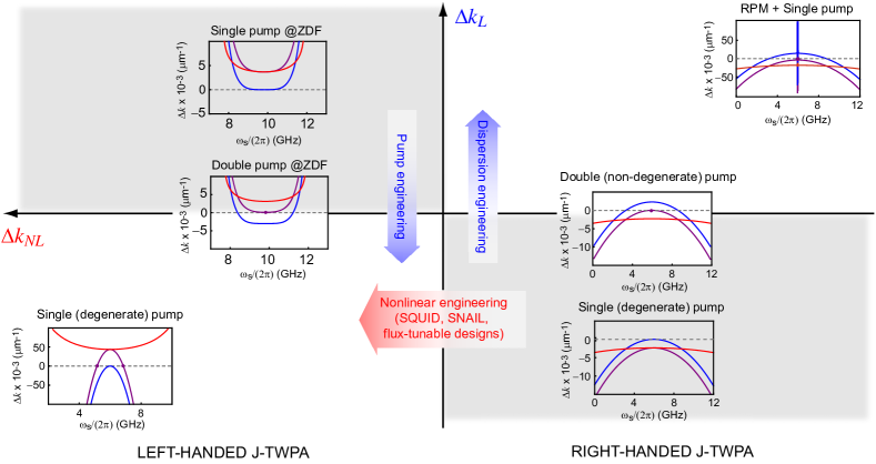
Nonetheless, the very feature of phase matching that bestows TWPAs with their inherently non-reciprocal gain, also turns out to be the key challenge in the way of realizing gain over large propagation distances and device geometries. This is because the presence of strong Josephson nonlinearity makes the effective refractive index, and hence the phase difference between interacting signal and pump waves, intensity-dependent. Furthermore, since the signal amplitude scales with distance due to amplification, it becomes challenging to compensate for phase mismatch due to both linear and nonlinear dispersion between different propagating frequencies throughout the propagation distance [28, 29]. Inspired by ideas used in traveling-wave fiber-optic amplifiers, recent studies have explored solutions such as dispersion engineering of J-TWPAs [15, 16, 30] that is rooted in modifying linear dispersion of the bare (unpumped) line to compensate for the nonlinear phase mismatch in the presence of the pump. Variations on this theme based on impedance engineering [31] and nonlinearity engineering [18, 21] also remain an area of active research. Figure 1 summarizes the different approaches adopted till date along with a sketch of representative device designs. As evident, almost all such approaches require increased complexity in design and fabrication of the circuit, loss of frequency tunability, and/or longer device lengths. Specifically, since dispersion-engineered designs typically involve additional circuit elements employing lossy dielectrics, the cumulative loss scales with length of the TWPA thus trading off one limitation for the other! Such concerns are especially pertinent when employing TWPAs as quantum-limited detectors and sources of squeezed radiation, applications where both pump tunability and low loss are imperative.
In this work, we propose a novel and simple design based on left-handed Josephson metamaterial that can realize low-noise broadband amplification without any need for complicated nonlinearity or dispersion engineering. The operation of a left-handed J-TWPA as a broadband amplifier is rooted in the compensation of linear dispersion-induced phase mismatch between signal(idler) and pump waves with nonlinearity-induced phase mismatch, an effect enabled by opposing directions of phase and group velocities in a left-handed transmission line. While left-handed transmission lines have been explored in linear optical applications, such as sub-wavelength focusing [32] and resonance cone formation [33, 34], their potential as nonlinear media for wave mixing has remained largely unexplored. Specifically, left-handed Josephson transmission lines (JTLs) constitute a new modality in microwave superconducting circuits, where all designs explored to date employ right-handed transmission lines embedded with Josephson junctions. As depicted in Fig. 1, left-handed JTLs effectively double the engineering landscape for J-TWPAs, introducing new operational regimes such as the ‘reversed dispersion’ [(e) in Fig. 1], which can be leveraged in combination of non-degenerate pumping for achieving a flat gain profile over a wide frequency range.
II Equation of Motion for Left-Handed J-TWPA
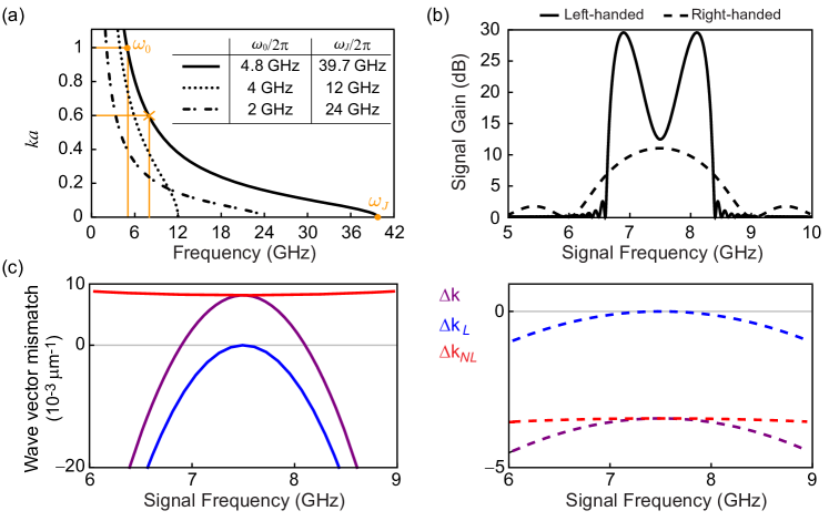
As shown in Fig. 1 the primary difference, between a left-handed Josephson transmission line (JTL) and the previous TWPAs designs designs based on right-handed JTL, is the exchange of the inductive () and capacitive () elements to be the parallel and series impedance elements in the transmission line respectively. The additional shunt capacitance denotes the intrinsic Josephson capacitance. The corresponding linear dispersion relation for the line is given by [Fig 2(a)],
| (1) |
where denotes the size of a unit cell, is the frequency of the propagating wave, is the Josephson plasma frequency that sets the cut-off frequency of the JTL waveguide, and is frequency corresponding to . It is worthwhile to note that in a left-handed JTL the directions of wave and energy propagation are anti-parallel, given the sign difference between the wave and group velocities,
| (2a) | ||||
| (2b) | ||||
II.1 Linear Amplification
In order to derive the wave equation for a left-handed JTL, we expand the Josephson cosine potential and retain only the leading order nonlinear term. Such a ‘perturbative’ approach is reasonable to describe the regime of linear amplification, when the current flowing through the junction remains small as compared to the critical current of the junction (). This leads to the following equation of motion for the for the propagating field amplitude, described in terms of the position-dependent flux variable (Supplementary Section I.A),
| (3) |
The first three terms in Eq. (3) describe the linear propagation, while the fourth term describes the nonlinear frequency mixing. It is worth noting that the nonlinearity appears directly in the flux amplitude (i.e. potential energy) here, unlike the right-handed J-TWPA where the nonlinearity appears in the kinetic energy term as [29, 15]. In order to derive linear amplification response of the left-handed JTL, we then develop the solution of the form
| (4) |
where indexes the pump, signal and idler waves respectively. Note that in contrast to previous theoretical proposals considering nonlinear optics of bulk metamaterials [35, 36], all three waves supported by the left-handed J-TWPA have negative group velocity. Performing harmonic balance dictated by energy conservation in the four-wave mixing process (), and solving the resultant coupled system of equations leads to the following expression for signal/idler amplitudes (Supplementary Section I.B),
| (5) |
Here and represent the cis- and trans-gain of the amplifier respectively,
| (6a) | |||
| (6b) | |||
| (6c) | |||
with denoting the gain per unit length of the amplifier, being the nonlinear coupling per unit length for signal and idler waves, and being the total wave vector mismatch between the wave propagating at pump frequency and a fixed signal (idler) frequency.
Figure 2(b) contrasts calculated for left-handed and right-handed J-TWPAs comprising and unit cells respectively, both pumped at a frequency . The stark difference in both the magnitude and profile of the frequency-dependent gain for left- vs right-handed designs is rooted in the frequency profiles of respective , which gets contributions both from the linear dispersion of the JTL , and the nonlinearity-induced self- and cross-phase modulation of the propagating signals , i.e. Notably, these two contributions are of opposite signs in a left-handed J-TWPA as shown in Fig. 2(c), since the signs of the and are determined by the wave velocity and group velocity respectively,
| (7a) | ||||
| (7b) | ||||
where, in the second step of each equation, we have used Eqs. (2) and parametrized signal/idler frequencies in terms of a dimensionless detuning from the pump, . Here, is the nonlinear mixing coefficient determined by the pump amplitude and frequency (Supplementary Section I.B). As evident from Eqs. (7), the relative sign difference between wave and group velocity in a left-handed metamaterial enables a left-handed J-TWPA to be phase-matched over a broad bandwidth 111Higher-order nonlinear effects such as group velocity dispersion need to be accounted for while analyzing high-pump power regime..
In contrast, in a right-handed J-TWPA both and , and hence linear and nonlinear wave vector mismatch, are restricted to be of the same sign owing to the always-convex dispersion of a right-handed JTL. To circumvent this issue, several approaches centered on either modifying [15] or [18, 21] have been explored in designs based on right-handed JTLs. Besides employing complicated design engineering, such solutions necessarily lead to other constraints. For instance, a common and widely adopted approach involves compensating the mismatch by periodically loading the line with resonant elements in order to open a band gap in [Fig. 1(c)]; this, however, leads to limited frequency tunability of the J-TWPA since now the pump needs to be tuned to be near the dispersion feature to avail of the intended linear mismatch to be compensated by the nonlinear mismatch in the presence of the pump. Similarly, engineering via SQUID-based designs require additional lines for flux control and complicated pump engineering. In contrast, the native phase matching property of left-handed J-TWPA significantly simplifies its design and operation. Furthermore, the resultant efficiency of the four-wave mixing process leads to a peak gain that scales exponentially with length of the line [unlike quadratic scaling in the ‘bare’ right-handed JTL, Fig. 1(b)], allowing usage of shorter lines which translates to reduced distributed loss and tighter fabrication control. Such considerations become especially crucial while evaluating prospects of J-TWPAs as sources of broadband squeezed radiation, where frequency-dependent line loss can severely limit the achievable squeezing [38, 39].
II.2 Unique features of Left-handed J-TWPA
In addition to phase matching over broad bandwidths, there are several unique features of left-handed J-TWPAs which we discuss in the following sections.
Peak Gain and Dynamic Range
The peak gain of 30 dB in Fig. 2(b) is realized at a frequency corresponding to a perfect wave matching condition, . In view of Eqs. (7), this corresponds to a relative detuning from the center (pump) frequency,
| (8) |
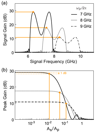
Note that, unlike right-handed design, doubly degenerate condition, i.e. , does not correspond to perfect phase matching in a left-handed J-TWPA. Furthermore, in the limit , the gain per unit cell at simplifies to As depicted in Fig. 3(a), this leads to a sharp increase in peak gain with decrease in pump frequency. This is another contrasting feature from right-handed J-TWPA, where higher gain is realized for higher pump frequencies [15, 29, 21, 18]. A critical advantage of this low-pass filtering property of the left-handed Josephson transmission line is the suppression of higher harmonic generation (Supplementary Section 4.A). Significant engineering efforts are being expended to eliminate the intermodulation products and sidebands mediated by these higher pump harmonics, that are known to decrease quantum efficiency and effective squeezing attainable with right-handed J-TWPAs [40].
The analysis until now assumes a “stiff” or undepleted pump amplitude irrespective of the signal gain, which strictly holds true under small signal approximation. However, as signal amplitude increases, either at the input or due to amplification down the line, and becomes comparable to pump amplitude, the amplifier response becomes nonlinear and pump depletion effects due to signal (idler) backaction need to be considered [3]. Figure 3(b) plots the result of a calculation including these effects, showing that gain of a left-handed J-TWPA rolls-off at high signal powers. Further, the gain compression sets in earlier when the same device is operated at lower pump frequencies. This is in accordance with the standard amplifier physics that higher gain leads to saturation for smaller signal powers [41], in conjunction with the fact that a left-handed J-TWPA realizes higher gain at lower . For a detailed comparison of dynamic range between the two J-TWPA modalities, we refer the reader to Supplementary Section 2.B.
Zero-dispersion frequency
Another feature unique to the left-handed J-TWPA is the existence of a “zero-dispersion frequency”, . The location of the corresponds to an inflection point of the dispersion relation, which leads to the following useful expression for its location, On the other hand a right-handed JTL, given its always-convex dispersion, cannot support a .
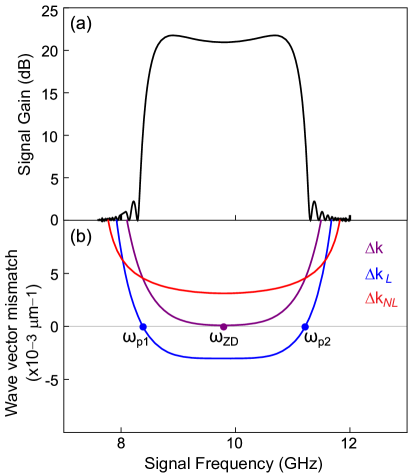
Further, flips sign as pump frequency is scanned across in a left-handed J-TWPA. Since in a left-handed J-TWPA, phase matching for signal frequencies in the range seems a nonstarter (Supplementary Section III)). In fact, this regime can be thought of as a perfect dual of the right-handed JTL where both and were negative. Nonetheless, it is worthwhile to note that the linear dispersion also has the flattest profile near since the curvature of the dispersion curves goes to zero at ; this bodes well for achieving a flat broadband gain if phase matching could indeed be achieved. We show that the latter problem can be circumvented via the use of non-degenerate dual pumps [3] in Figure 4(a) (Supplementary Section II).
As evident, a double-pumped left-handed J-TWPA achieves an almost flat gain profile, realizing a gain in excess of dB gain over a bandwidth of about . The flat profile of the gain achieved with non-degenerate pumping is consistent with the shape of the corresponding phase mismatch curves shown in Fig. 4(b). Note that double pumping nulls the linear dispersion, , at the two pump frequencies leading to a for . Combined with a , this leads to a perfect wave vector match at the center frequency resulting in a flat broadband gain. We note that the dynamic range in the two-pump non-degenerate pumping case remains the same as the single pump case for nominally identical small signal gain values.
III Discussion
In summary, we have presented a natively phase-matched left-handed J-TWPA platform which achieves low noise broadband amplification by exploiting the opposing signs of group and phase velocity in a left-handed Josephson transmission line (JTL). The simplicity of the proposed design precludes the need for any complicated circuit or nonlinearity engineering, significantly easing the fabrication of J-TWPA devices. In addition, it supports unique features such as existence of a reversed dispersion regime that can realize flat broadband gain by simply changing the operation frequency and employing non-degenerate pumps.
The principles developed in our work considerably expand the design landscape of generic traveling-wave amplifiers. Further, they provide a framework to inform design vs operational trade-offs, such as maximum gain at specific frequencies vs constant gain over wide bandwidths, in a given (right-handed vs left-handed) metamaterial platform. We elucidate this in Fig. 5 that incorporates several insights generated during the course of this research to present a unified view of several J-TWPA designs, each of which can be placed in the relevant quadrant depending on the relative sign difference between linear () and nonlinear () wave vector mismatch. The aim of J-TWPA engineering is to be in the white quadrants of Fig. 5, where perfect phase matching can be realized via optimization of design and/or operation of a given device. The ‘bare’ left-handed J-TWPA already lies in a favorable quadrant in this plane, unlike the ‘bare’ right-handed J-TWPA; a potential means to move between these quadrants is to modify the nonlinear phase contribution by means of engineering the Josephson nonlinearity, such as those employed in Refs. [18] and [21], though at the cost of more involved designs that employ flux-tunable Josephson circuits [Fig. 1(d)].
Similarly, linear phase engineering determines the movement along the y-axis, typically accomplished via either circuit engineering to modify the line dispersion [15] or pump engineering, as discussed in the case of a left-handed J-TWPA operated near . This representation also shows how naively combining two approaches can be detrimental to the cause: for instance, while double-pumping a bare right-handed J-TWPA improves phase matching, double-pumping a resonantly phase-matched (RPM) version can spoil it. This is because the advantage of engineering a positive , via an RPM-induced band gap in the line dispersion, is negated by pinning the dispersion curve to be zero near the two pump frequencies. By simple inspection, one can see that given the convex dispersion for both the right-handed JTL, and left-handed JTL below , the is always pushed along the positive axis, while the opposite is true for a left-handed J-TWPA pumped above . Thus, the diagram serves as a useful guide in understanding the landscape of distributed amplifier designs, with the arrows indicating optimal strategies to achieve efficient broadband amplification through a combination of nonlinear (x-axis) and linear (y-axis) phase engineering.
Interestingly, even in terms of parameter optimization, left-handed J-TWPA perfectly complements its right-handed counterparts. Designing left-handed JTLs that operate in the standard 4-12 GHz frequency range of interest for applications such as qubit readout, while maintaining short line lengths (with less than 1000 unit cells) and being impedance matched to 50 external microwave circuitry, constrains the junction critical currents in the range of few hundred nAs; this makes the junction fabrication amenable to planar electron beam lithography instead of complicated trilayer fabrication needed for large junctions employed in right-handed designs. The price to pay is the reduced dynamic range which can be enhanced either by implementing the requisite inductance to using an array of larger junctions or switching to longer line lengths. Correspondingly, the inline capacitance is accordingly higher than the right-handed designs, which leads to higher overall loss in the left-handed designs; nonetheless, this again can be compensated by exploiting the higher efficiency of the natively phase-matched four-wave mixing process and using shorter lines (Supplementary Section 4.B). One other crucial advantage of the higher gain per unit length in the left-handed design is the enhanced robustness to disorder in the JTL [42].
Given the rapidly growing relevance of Josephson parametric circuits in platforms as diverse as superconducting qubits [43], semiconductor quantum dots [44], quantum acoustics [45] and quantum optomechanics [46], the left-handed JTL investigated here provides new ground for exploration and optimization of such devices. Since linear left-handed transmission lines have recently been experimentally demonstrated in superconducting circuit platforms [47], the left-handed J-TWPA proposed here is within easy reach of current state-of-the-art in the field. In combination with upcoming ideas such as Floquet-mode pumping [40] and designs employing novel nonlinear elements, such as SNAIL [48] and superinductances [49, 50], we hope that the present work will help accelerate development of amplifiers that can address long-standing challenge of broadband squeezing, a critical functionality for both information processing and quantum sensing.
Acknowledgements.
The authors wish to thank Tristan Brown and Jamie Kerman for comments on the manuscript, and especially Kevin O’Brien for insightful discussions and generously sharing the details of the open source JTWPA simulator. This research was supported by NSF under grant number DMR-2047357. V.P. acknowledges support from NSF under grant number DMR- 2004298.References
- Yurke et al. [1989] B. Yurke, L. R. Corruccini, P. G. Kaminsky, L. W. Rupp, A. D. Smith, A. H. Silver, R. W. Simon, and E. A. Whittaker, Phys. Rev. A 39, 2519 (1989).
- Yamamoto et al. [2008] T. Yamamoto, K. Inomata, M. Watanabe, K. Matsuba, T. Miyazaki, W. D. Oliver, Y. Nakamura, and J. S. Tsai, Journal of Applied Physics 93, 10.1063/1.2964182 (2008).
- Kamal et al. [2009] A. Kamal, A. Marblestone, and M. Devoret, Phys. Rev. B 79, 184301 (2009).
- Bergeal et al. [2010] N. Bergeal, F. Schackert, M. Metcalfe, R. Vijay, V. E. Manucharyan, L. Frunzio, D. E. Prober, R. J. Schoelkopf, S. M. Girvin, and M. H. Devoret, Nature Physics 465, 64 (2010).
- Stehlik et al. [2015] J. Stehlik, Y.-Y. Liu, C. M. Quintana, C. Eichler, T. R. Hartke, and J. R. Petta, Phys. Rev. Applied 4, 014018 (2015).
- Didier et al. [2015] N. Didier, A. Kamal, W. D. Oliver, A. Blais, and A. A. Clerk, Phys. Rev. Lett. 115, 093604 (2015).
- Martin et al. [2020] L. S. Martin, W. P. Livingston, S. Hacohen-Gourgy, H. M. Wiseman, and I. Siddiqi, Nature Physics 16, 1046 (2020).
- Mutus et al. [2014] J. Y. Mutus, T. C. White, R. Barends, Y. Chen, Z. Chen, B. Chiaro, A. Dunsworth, E. Jeffrey, J. Kelly, A. Megrant, C. Neill, P. J. J. O’Malley, P. Roushan, D. Sank, A. Vainsencher, J. Wenner, K. M. Sundqvist, A. N. Cleland, and J. M. Martinis, Applied Physics Letters 104, 263513 (2014).
- Roy et al. [2015] T. Roy, S. Kundu, M. Chand, A. M. Vadiraj, A. Ranadive, N. Nehra, M. P. Patankar, J. Aumentado, A. A. Clerk, and R. Vijay, Applied Physics Letters 107, 262601 (2015).
- Liu et al. [2017] G. Liu, T.-C. Chien, X. Cao, O. Lanes, E. Alpern, D. Pekker, and M. Hatridge, Applied Physics Letters 111, 202603 (2017).
- Frattini et al. [2018] N. E. Frattini, V. V. Sivak, A. Lingenfelter, S. Shankar, and M. H. Devoret, Phys. Rev. Applied 10, 054020 (2018).
- Metelmann and Clerk [2014] A. Metelmann and A. A. Clerk, Phys. Rev. Lett. 112, 133904 (2014).
- Kamal and Metelmann [2017] A. Kamal and A. Metelmann, Phys. Rev. Applied 7, 034031 (2017).
- Esposito et al. [2021] M. Esposito, A. Ranadive, L. Planat, and N. Roch, Applied Physics Letters 119, 120501 (2021).
- O’Brien et al. [2014] K. O’Brien, C. Macklin, I. Siddiqi, and X. Zhang, Phys. Rev. Lett. 113, 157001 (2014).
- White et al. [2015] T. C. White, J. Y. Mutus, I.-C. Hoi, R. Barends, B. Campbell, Y. Chen, Z. Chen, B. Chiaro, A. Dunsworth, E. Jeffrey, J. Kelly, A. Megrant, C. Neill, P. J. J. O’Malley, P. Roushan, D. Sank, A. Vainsencher, J. Wenner, S. Chaudhuri, J. Gao, and J. M. Martinis, Applied Physics Letters 106, 242601 (2015).
- Macklin et al. [2015] C. Macklin, K. O’Brien, D. Hover, M. E. Schwartz, V. Bolkhovsky, X. Zhang, W. D. Oliver, and I. Siddiqi, Science 350, 307 (2015).
- Bell and Samolov [2015] M. T. Bell and A. Samolov, Phys. Rev. Applied 4, 024014 (2015).
- Miano and Mukhanov [2019] A. Miano and O. A. Mukhanov, IEEE Transactions on Applied Superconductivity 29, 1 (2019).
- Grimsmo et al. [2021] A. L. Grimsmo, B. Royer, J. M. Kreikebaum, Y. Ye, K. O’Brien, I. Siddiqi, and A. Blais, Phys. Rev. Applied 15, 034074 (2021).
- Ranadive et al. [2021] A. Ranadive, M. Esposito, L. Planat, E. Bonet, C. Naud, O. Buisson, W. Guichard, and N. Roch, A reversed kerr traveling wave parametric amplifier (2021), arXiv:2101.05815 [quant-ph] .
- Ho Eom et al. [2012] B. Ho Eom, P. Day, H. LeDuc, and J. Zmuidzinas, Nature Physics 8, 623 (2012).
- Bockstiegel et al. [2014] C. Bockstiegel, J. Gao, M. R. Vissers, M. Sandberg, S. Chaudhuri, A. Sanders, L. R. Vale, K. D. Irwin, and D. P. Pappas, Journal of Low Temperature Physics 176, 476 (2014).
- Erickson and Pappas [2017] R. P. Erickson and D. P. Pappas, Phys. Rev. B 95, 104506 (2017).
- Adamyan et al. [2016] A. A. Adamyan, S. E. de Graaf, S. E. Kubatkin, and A. V. Danilov, Journal of Applied Physics 119, 083901 (2016).
- Vissers et al. [2016] M. R. Vissers, R. P. Erickson, H.-S. Ku, L. Vale, X. Wu, G. C. Hilton, and D. P. Pappas, Applied Physics Letters 108, 012601 (2016).
- Malnou et al. [2021] M. Malnou, M. Vissers, J. Wheeler, J. Aumentado, J. Hubmayr, J. Ullom, and J. Gao, PRX Quantum 2, 010302 (2021).
- Agrawal [2019] G. P. Agrawal, in Nonlinear Fiber Optics (Sixth Edition), edited by G. P. Agrawal (Academic Press, 2019) sixth edition ed., pp. 401–462.
- Yaakobi et al. [2013] O. Yaakobi, L. Friedland, C. Macklin, and I. Siddiqi, Phys. Rev. B 87, 144301 (2013).
- Planat et al. [2020] L. Planat, A. Ranadive, R. Dassonneville, J. Puertas Martínez, S. Léger, C. Naud, O. Buisson, W. Hasch-Guichard, D. M. Basko, and N. Roch, Phys. Rev. X 10, 021021 (2020).
- Zhao et al. [2019] S. Zhao, S. Withington, D. J. Goldie, and C. N. Thomas, Journal of Physics D: Applied Physics 52, 415301 (2019).
- Grbic and Eleftheriades [2004] A. Grbic and G. V. Eleftheriades, Phys. Rev. Lett. 92, 117403 (2004).
- Balmain et al. [2002] K. Balmain, A. Luttgen, and P. Kremer, IEEE Antennas and Wireless Propagation Letters 1, 146 (2002).
- Chshelokova et al. [2012] A. V. Chshelokova, P. V. Kapitanova, A. N. Poddubny, D. S. Filonov, A. P. Slobozhanyuk, Y. S. Kivshar, and P. A. Belov, Journal of Applied Physics 112, 073116 (2012).
- Popov and Shalaev [2006] A. K. Popov and V. M. Shalaev, Opt. Lett. 31, 2169 (2006).
- Litchinitser et al. [2007] N. M. Litchinitser, I. R. Gabitov, and A. I. Maimistov, Phys. Rev. Lett. 99, 113902 (2007).
- Note [1] Higher-order nonlinear effects such as group velocity dispersion need to be accounted for while analyzing high-pump power regime.
- Grimsmo and Blais [2017] A. L. Grimsmo and A. Blais, npj Quantum Information 3, 20 (2017).
- Houde et al. [2019] M. Houde, L. Govia, and A. Clerk, Phys. Rev. Applied 12, 034054 (2019).
- Peng et al. [2021] K. Peng, M. Naghiloo, J. Wang, G. D. Cunningham, Y. Ye, and K. P. O’Brien, Near-ideal quantum efficiency with a floquet mode traveling wave parametric amplfier (2021), arXiv:2104.08269 [quant-ph] .
- Abdo et al. [2013] B. Abdo, A. Kamal, and M. Devoret, Phys. Rev. B 87, 014508 (2013).
- Karlsson [1998] M. Karlsson, J. Opt. Soc. Am. B 15, 2269 (1998).
- Aumentado [2020] J. Aumentado, IEEE Microwave Magazine 21, 45 (2020).
- Schaal et al. [2020] S. Schaal, I. Ahmed, J. A. Haigh, L. Hutin, B. Bertrand, S. Barraud, M. Vinet, C.-M. Lee, N. Stelmashenko, J. W. A. Robinson, J. Y. Qiu, S. Hacohen-Gourgy, I. Siddiqi, M. F. Gonzalez-Zalba, and J. J. L. Morton, Phys. Rev. Lett. 124, 067701 (2020).
- Andersson et al. [2021] G. Andersson, S. W. Jolin, M. Scigliuzzo, R. Borgani, M. O. Tholén, J. C. R. Hernández, V. Shumeiko, D. B. Haviland, and P. Delsing, Squeezing and multimode entanglement of surface acoustic wave phonons (2021), arXiv:2007.05826 [quant-ph] .
- Heikkilä et al. [2014] T. T. Heikkilä, F. Massel, J. Tuorila, R. Khan, and M. A. Sillanpää, Phys. Rev. Lett. 112, 203603 (2014).
- Wang et al. [2019] H. Wang, A. Zhuravel, S. Indrajeet, B. Taketani, M. Hutchings, Y. Hao, F. Rouxinol, F. Wilhelm, M. LaHaye, A. Ustinov, and B. Plourde, Phys. Rev. Applied 11, 054062 (2019).
- Sivak et al. [2019] V. Sivak, N. Frattini, V. Joshi, A. Lingenfelter, S. Shankar, and M. Devoret, Phys. Rev. Applied 11, 054060 (2019).
- Masluk et al. [2012] N. A. Masluk, I. M. Pop, A. Kamal, Z. K. Minev, and M. H. Devoret, Phys. Rev. Lett. 109, 137002 (2012).
- Sivak et al. [2020] V. V. Sivak, S. Shankar, G. Liu, J. Aumentado, and M. H. Devoret, Phys. Rev. Applied 13, 024014 (2020).