![]()
| Crack patterns of drying dense bacterial suspensions† | |
| Xiaolei Ma,∗a Zhengyang Liu,a Wei Zeng,ab Tianyi Lin,a Xin Tian,c and Xiang Cheng∗a | |
![[Uncaptioned image]](/html/2201.00441/assets/x2.png)
|
Drying of bacterial suspensions is frequently encountered in a plethora of natural and engineering processes. However, the evaporation-driven mechanical instabilities of dense consolidating bacterial suspensions have not been explored heretofore. Here, we report the formation of two different crack patterns of drying suspensions of Escherichia coli (E. coli) with distinct motile behaviors. Circular cracks are observed for wild-type E. coli with active swimming, whereas spiral-like cracks form for immotile bacteria. Using the elastic fracture mechanics and the poroelastic theory, we show that the formation of the circular cracks is determined by the tensile nature of the radial drying stress once the cracks are initiated by the local order structure of bacteria due to their collective swimming. Our study demonstrates the link between the microscopic swimming behaviors of individual bacteria and the mechanical instabilities and macroscopic pattern formation of drying bacterial films. The results shed light on the dynamics of active matter in a drying process and provide useful information for understanding various biological processes associated with drying bacterial suspensions. |
1 Introduction
Active matter is a class of nonequilibrium systems consisting of autonomous units that convert local internal or ambient free energy into mechanical motions. A large number of biological and physical systems including suspensions of self-propelled cytoskeleton1, 2, swarms of bacteria3, 4, 5 and clusters of synthetic active colloids6, 7, 8 can be categorized as active matter, which exhibit fascinating statistical and mechanical properties that draw tremendous attention in recent years due to their fundamental and technical interests 9, 10, 11. While extensive studies have been conducted in understanding the emergent collective dynamics of active matter in fluid states 12, 13, it is still unclear whether and how local activity affects the macroscopic mechanical properties of consolidating active matter during a drying process.
Drying of bacterial suspensions as a premier model of active matter plays a crucial role in many biological, environmental and industrial processes and influences diverse phenomena ranging from biofilm formation 14, spreading of disease 15 and food hygiene 16 to interbacterial competition for survival 17, coating and self-assembly 18, 19, 20. The active swimming of bacteria can profoundly modify the complex interplays between solid, liquid and vapor phases as a suspension passes from a fluid to a solid state during drying, giving rise to the unusual growth dynamics and morphologies of “coffee rings” in dried deposits 18, 21, 19, 20, 22. However, these existing studies are all limited to the dilute limit of bacterial suspensions, where bacteria are deposited near the edge of drying drops. The mechanical instabilities of thick consolidating bacterial films formed by drying dense bacterial suspensions remain elusive, despite that such instabilities and the resulting crack patterns have been extensively investigated in counterpart passive particle systems 23, 24, 25, 26, 27, 28, 29, 30, 31, 32.
Here, we explored the effect of bacterial swimming on the mechanical instabilities and desiccation crack patterns of dense consolidating bacterial suspensions. We used a wild-type strain of Escherichia coli (E. coli) as our model bacteria, which display the classic run-and-tumble swimming in water 33. As a control, we also examined a mutant strain of E. coli that show only tumbling. Below, we shall refer to the wild-type E. coli as swimmers and the mutant E. coli as tumblers. While spiral-like cracks were found in the dried deposits of tumblers and dead swimmers, we observed circular cracks in the dried deposits of swimmers. Using the elastic fracture mechanics and the poroelastic theory, we showed that the circular cracks form due to the tensile nature of the radial drying stress once the cracks are initiated by the local order structure induced by the collective swimming of wild-type E. coli. In contrast, the spiral-like cracks arise from a dynamic interplay between cracking and delamination of the drying films of immotile bacteria. Our study unambiguously demonstrates the crucial effect of bacterial swimming on the mechanical instabilities of consolidating bacterial films and illustrates the unique features of active matter in infamously complicated drying processes. Our results are also helpful for deciphering different desiccation crack patterns of dried bacterial films encountered in natural and engineering processes.
2 Experiment
We used two different E. coli strains with distinct swimming behaviors in our experiments, i.e., a wild-type strain of swimmers (BW25113) and a mutant strain of tumblers (RP1616). The two strains share a similar body geometry, which has the average length of 3-4 m and the average width of m (Figs. 1a and d). The culturing protocols of the two strains are detailed elsewhere5, 4. In addition, we have also studied the drying behaviors of suspensions of dead swimmers. The dead bacteria were obtained from suspensions of active wild-type swimmers sitting in sealed micro-centrifuge tubes for at least four days. The bacteria were confirmed to be immotile from direct optical microscopy. To avoid any potential complication due to the change of buffer quality over the long waiting, we washed the dead bacteria and resuspended them in DI water at the targeted concentration before each experiment.
In a typical experiment, we prepared a suspension of bacteria with an initial volume fraction of 10-20%. A microscope glass slide cleaned with DI water and dried by a blowgun was used as the substrate, which was hydrophilic with a water contact angle 25∘. A drop of the suspension with an initial volume of 2-3 L was gently deposited onto the substrate for drying. A bright-field inverted microscope was used to image the drying process at a frame rate of 1-20 fps. All experiments were performed at a room temperature of 20 2 ∘C with a relative humidity of . We used a scanning electron microscope (SEM) to image the microstructures of dried bacterial deposits, and an optical non-contact profilometer to measure the temporal evolution of the height profiles of drying bacterial films.
3 Results
3.1 Circular cracks of wild-type swimming bacteria
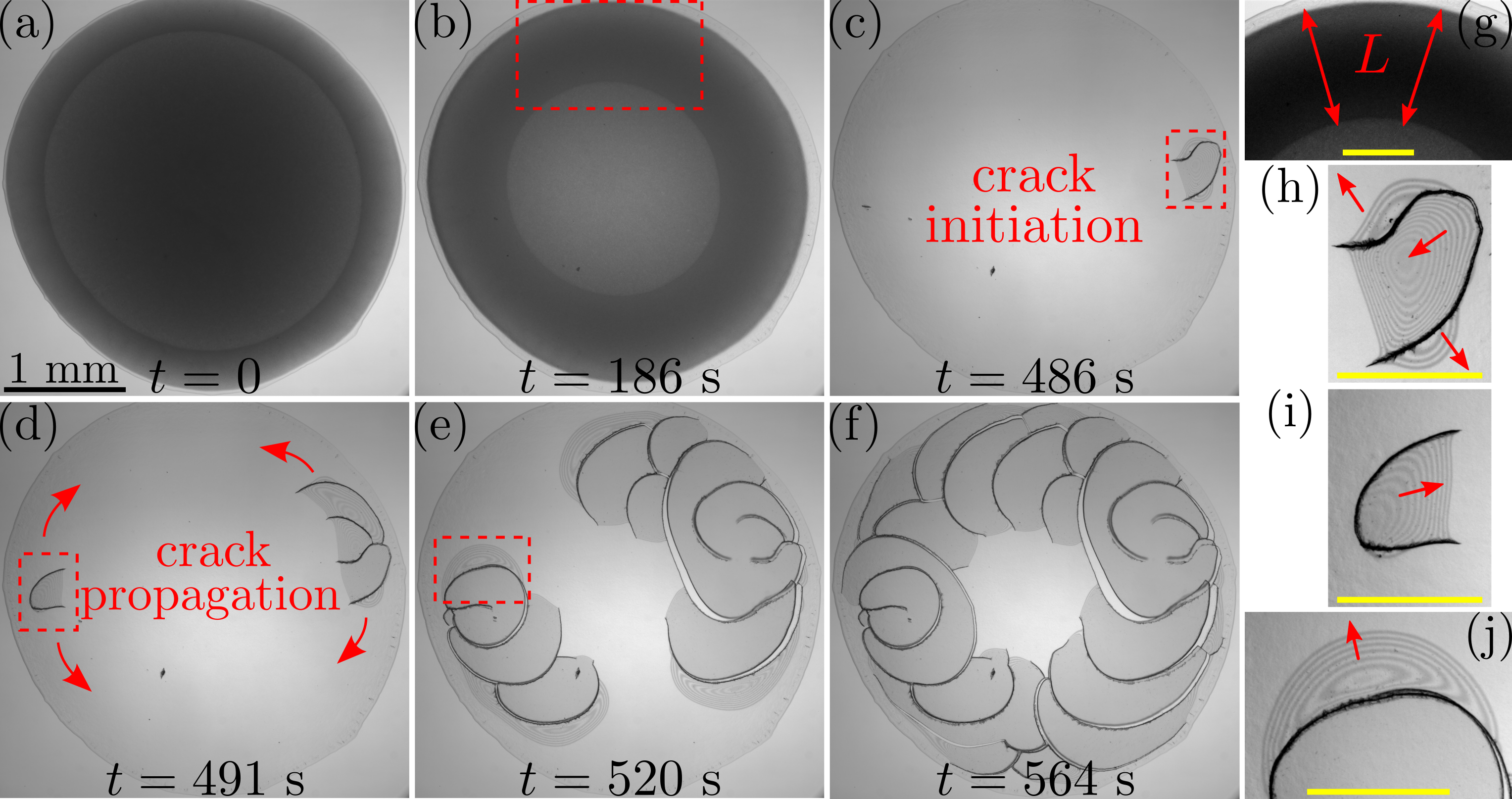
We observed circular cracks in the dried deposits of suspensions of wild-type swimmers (Figs. 1b and c). Figures 2a-f show the snapshots of different stages during the formation of circular cracks by drying a drop of a swimmer suspension with 2.5 L and . After the drop was deposited on the substrate (Fig. 2a), evaporation initially occurred predominantly near the pinned contact line of the drop, driving the formation of a compaction front where the concentration of bacteria increased drastically from in the bulk fluid to that close to the random close packing in the consolidating film . The compaction front displayed an approximately constant length (Fig. 2g), and continuously moved toward the center of the drop over a time interval of 414 s (Fig. 2b and Video S1 in ESI†). After the passing of the compaction front, the bacterial film was wet and gel-like and continued to undergo evaporation along the top surface of the film, leading to the accumulation of stress. Once the critical material strength was reached around 427 s, cracks were initiated near the edge of the film to release the excess stress 34 (Figs. 2c and 2h), which then propagated along a circular path (Figs. 2d-2e) over a short interval of about 73 s in a stick-slip fashion and eventually formed the circular cracks (Fig. 2f). Accompanying the crack propagation, the film also delaminated radially toward the drop’s center as indicated by the interference fringes in Figs. 2i-2j.
To interpret the circular cracks of wild-type swimmers, we calculate the stress distributions in the consolidating bacterial film. Figure 3a illustrates the geometry of a consolidating film in a cylindrical coordinate. Drying stress was accumulated in the film behind the compaction front in response to the continuously decreasing local liquid pore pressure over time. As evaporation proceeded, the film became flat and thin and evaporation predominantly occurred at the top surface of the film in the late stage of drying. Therefore, satisfies a one-dimensional diffusion equation with defined at the top surface of the film 35, 36:
| (1) |
where is the dynamic viscosity of water and is the Young’s modulus of the dehydrated film on glass substrate. We estimated 100 MPa based on our direct measurement using atomic force microscopy, which is consistent with the reported modulus of an isolated dehydrated bacterium37. Although the Young’s moduli of isolated bacteria and bacterial films are of the same order of magnitude at the microscopic scales, the latter is generally larger depending on substrate stiffness, humidity, bacterial type and even the fitting model 38, 39, 40, 41. Here, is the permeability of the film, which is given by the Carman–Kozeny relation m2, is the packing fraction of bacteria (Appendix C) and m is the characteristic size of bacteria. The initial condition is , where Pa is the atmospheric pressure. The boundary conditions is , where is the steady surface evaporation rate. The evaporation rate is expressed as 42, in which m2 s is the diffusion coefficient of water into air at the room temperature, mm is the drop radius pinned at the contact line, is the water density in the vapor at the air-water interface, is the water density in the bulk liquid, for a contact angle , and the relative humidity . Therefore, m/s. Solving Eq. 1, we have given by 43:
| (2) |
where
| (3) |
represents the deviation of the pore pressure from the atmospheric pressure. Here, is a constant.
During consolidation, a film is constricted by the substrate, thus the out-of-plane strain is significantly larger than the in-plane strain driven by shrinkage. Figure 3b shows the temporal variation of the height profile along a diameter of a consolidating film from 10 min to 19 min, during which a circular crack forms as indicated by the sharp drop of at mm. The film thickness decreases significantly during this period, whereas the in-plane contraction is negligible, suggesting that . Furthermore, since the top surface of the film is traction-free, the deformation of the thin film is predominantly driven by the in-plane stress, suggesting 42, 36. The same strain and stress conditions have also been applied in modeling the drying of colloidal suspensions on rigid glass substrates28.
The in-plane stress components and responsible for crack formation are correlated by the equilibrium condition of the stress field in the cylindrical coordinate:
| (4) |
Using the Biot constitutive relation of homogeneous and isotropic solids 35 under the approximations and , we have (Eq. A3 in Appendix A):
| (5) |
where is Poisson’s ratio of the bacterial film. Given the boundary condition , and can be analytically solved with Eqs. 4 and 5 (Eqs. A6 and A7 in Appendix A):
| (6) | |||
| (7) |
where the film-thickness-averaged liquid pressure (Eq. A5 in Appendix A).
It has been shown that biofilms including those of E. coli behave mechanically similar to polymeric materials, which have Poisson’s ratios ranging between 0.4 and 0.5. The range has been adopted in many previous experimental, numerical and theoretical studies on biofilms44, 45, 46, 47, 48, 49, 38, 50. Here, we took the lower bound of to accommodate the condition that the bacteria film was still undergoing drying at the point of cracking. Choosing any value between 0.4 and 0.5 would not qualitatively change our results. With mm and m (the thickness of the film at which the crack is generated, see Fig. 3b), Eqs. 6 and 7 predict the spatiotemporal stress distributions within the drying film.
Figure 3c shows and at a fixed location where the cracks formed in the experiment. Note that is tensile () and reaches 105 Pa when s, suggesting the formation of the cracks in the circumferential direction at large times. Here, is the critical stress for cracking, which can be estimated based on the the critical film thickness at which cracks form (Appendix B). In comparison, is compressive (), precluding the formation of cracks in the radial direction that are commonly observed in the drying films of colloidal suspensions 42, 51 based on the principle of fracture mechanics. Note that for drying colloidal suspensions with a typical Poisson’s ratio of , 52, 53, 54, 55 is tensile, which allows for the formation of radial cracks.
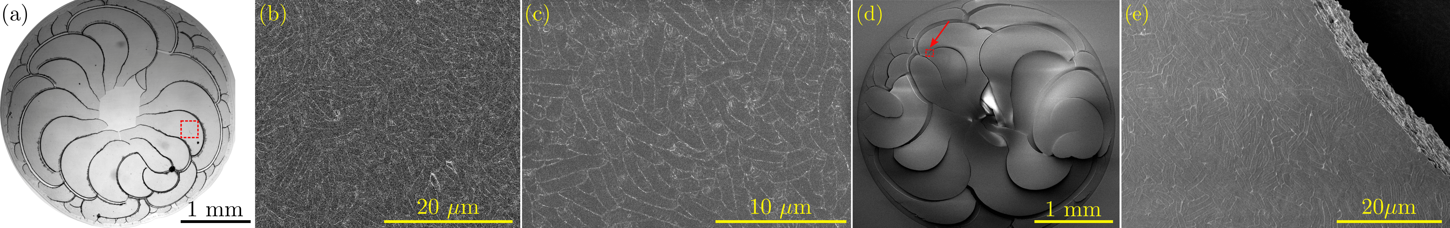
In addition to changing the mechanical properties of drying bacterial films, the active swimming of bacteria also modifies the microscopic structure of the consolidating bacterial films, which further facilitates the formation of circular cracks. Figure 4a shows the two-dimensional (2D) flow field of a suspension of wild-type swimmers near the compaction front during drying, which exhibits the characteristic swarming vortices induced by bacterial collective swimming4, 5. Such a coherent dynamic structure was preserved throughout the drying course and gave rise to the local order packing of bacteria in the dried deposit as indicated by the red arrows in Fig. 4b. The circular crack marked by the yellow arrows propagated through this local order structure.
It has already been shown that drying cracks prefer to propagate along the order direction of underlying microstructures due to the least resistance to release stress during crack propagation27. In the simple case of drying suspensions of colloidal ellipsoids where the ellipsoids align parallel to the contact line of drying films, the effect leads to the formation of circular cracks along the circumference of dried annular deposits27. In a drying bacterial film, although the swarming vortices do not align along the circumference of the drying film, the order structure should still act locally as a nucleation point, promoting the formation of the initial crack at small bacterial scales. As swarming vortices are mesoscopic on the order of a few tens of microns, the structure of the drying film at large scales is still isotropic. Thus, upon nucleation and after the size of the initial crack reaches the scale of a single swarming vortex, the drying film can be treated as a homogeneous medium with isotropic mechanical properties for the propagation of cracks at large scales. The radial tensile stress calculated in our simple homogeneous model should then be valid, which directs the propagation of cracks and eventually leads to the formation of circular cracks in the dried deposit.
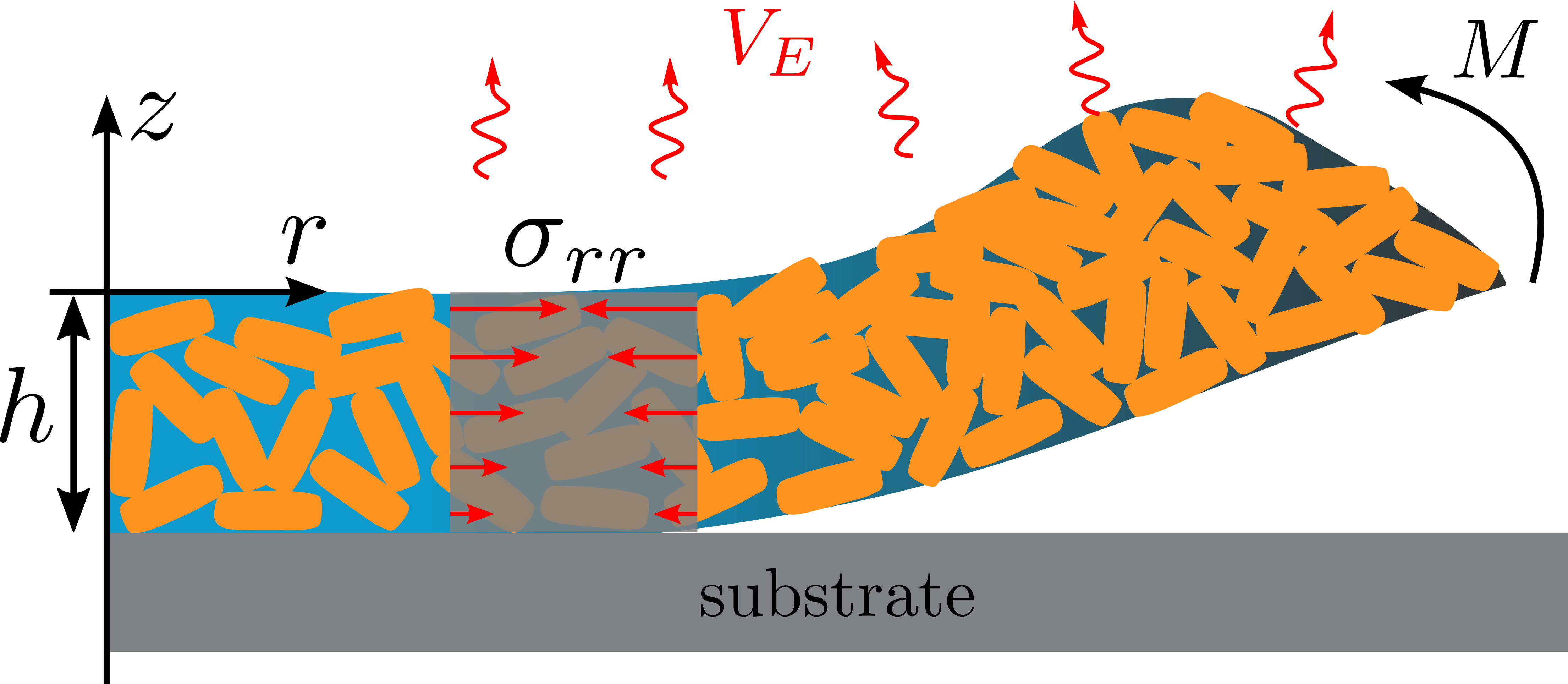
Finally, Figs. 2i-j show that along with the propagation of the circular cracks, the film also delaminated toward the center of the drying drop. Owing to the strong humidity gradient across the film thickness during drying 56, the in-plane tensile stress is localized near the top surface of the film, which gives rise to a stress gradient across the film as illustrated in Fig. 5. Such a stress gradient creates a bending moment , promoting the film delamination from the edge of the drop to the center of the drop once the accumulated stress is beyond the critical stress for delamination 56, 43, 57. We estimated both the critical stress for cracking and the critical stress for delamination (Appendix B), which are of the same order of magnitude of Pa. Hence, immediately following the formation of the circular cracks, the film delaminated from the new crack surface toward the center of the drying drop. Figure 1c shows the height profile of a completely-dried swimmer film, which quantitatively illustrates the extent of film delamination. The part of the film close to the inner edge has a height over 90 m above the substrate (the red color), while the thickness of the bacterial film near the pinned contact line (the blue color), as well as in the final stage of the drying process before delamination (Fig. 3b), is less than 30 m.
3.2 Spiral-like cracks of immotile bacteria
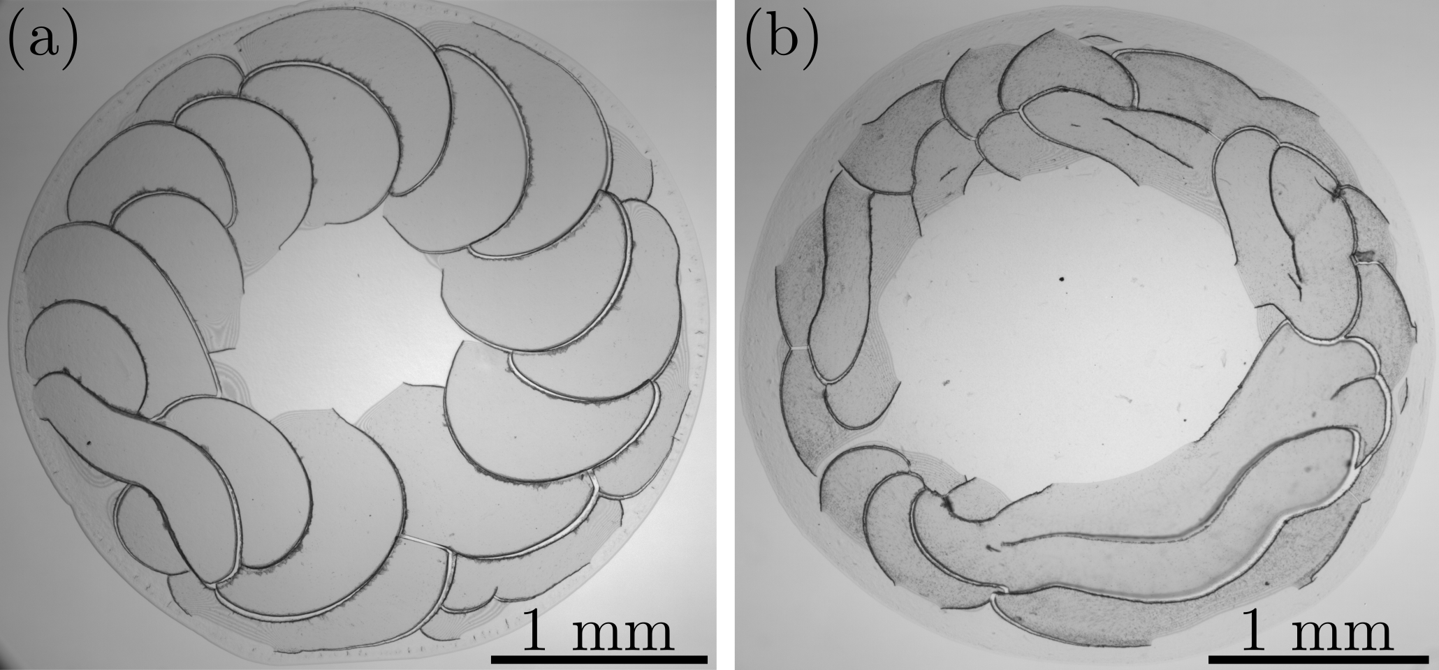
To verify the role of active swimming in the formation of circular cracks, we further examined the crack patterns of mutant tumblers as well as dead swimmers. Neither of the two types of bacteria showed the collective swimming in drying drops. In contrast to the circular cracks of wild-type swimmers, we observed spiral-like cracks in the dried deposits of these two types of immotile bacteria as shown in Figs. 1d-f and 6.
Figures 7a-f show the snapshots of different stages during the formation of the spiral-like cracks by drying a drop of a tumbler suspension with L and = 14 %. The compaction front of the drying tumbler suspension was significantly wider than that of the drying swimmer suspension (Fig. 2) and increased in width over time (comparing Videos S1 and S3 in ESI†). As the accumulated stress reached the material strength, hairpin-shaped cracks facing the center of the drying film first appeared (boxed regions in Figs. 7c and d), which simultaneously initiated film delamination between the two arms of the hairpins (interference fringes in Figs. 7h and i). Upon the creation of new surfaces by cracking, the film subsequently delaminated perpendicularly to and outside the arms of the hairpins and propagated along the circumferential direction (Fig. 7h). The delamination front showed an arc shape, which triggered the formation of a crack of the same shape at the front (Figs. 7e and j). The crack in turn created a new surface for further delamination. This cycle of cracking and delamination repeated with time until the cracks initiated by different hairpins met, which ultimately resulted in the spiral-like crack pattern shown in Fig. 7f. Thus, the spiral-like cracks of immotile bacteria stem from the dynamic interplay between film cracking and delamination.
Due to the absence of the collective swimming, tumblers were isotropically distributed in a dried deposit as evidenced in Fig. 8, in contrast to the local order structure in the dried deposit of wild-type swimmers (Fig. 4b). Figure 1f further shows the height profile of the dried deposit of tumblers. By comparing Figs. 1c and f, one can see that, near the inner drop edge, the degree of delamination of the deposit of swimmers was much stronger than that of tumblers. The observation indicates that the dried deposit of active swimmers was thicker near the edge than that of immotile tumblers, as the bending moment responsible for film delamination is proportional to the film thickness58. Thus, from the conservation of the number of bacteria, the thickness of the deposit of tumblers should be more uniform than that of swimmers. The conclusion is further supported by the direct observation that the extent of the dried deposit of tumblers was larger than that of swimmers (comparing Figs. 1b and e). The more uniform deposit of tumblers likely arose due to the underlying uniform amorphous structure of bacteria with a relatively low packing density. In contrast, swimmers exhibited a local order structure of a high packing density near the pinned contact line, while maintained an amorphous structure of a low packing density near the center.
Our systematic control experiments on the drying suspensions of mutant tumblers and dead wild-type swimmers demonstrate that the local order structure driven by the collective swimming of wild-type bacteria plays an important role in the formation of circular cracks. More broadly, our experiments show that the crack patterns in the consolidating films of microorganisms can be tuned by manipulating the swimming behaviors of microorganisms.
4 Discussion and conclusions
It is interesting to compare the similarities and differences between crack patterns of drying bacterial suspensions and drying suspensions of colloidal ellipsoids. First, counterintuitively, the crack pattern of immotile bacteria is different from that of colloidal ellipsoids. In drying suspensions of colloidal ellipsoids, driven by the hydrodynamic torque of capillary flow, the ellipsoids align with their major axes parallel to the pinned contact line, which leads to a nematic order structure near the contact line. As cracks propagate preferably along the order direction, this order structure gives rise to circular cracks in the dried deposit 27. In contrast, immotile bacteria show an amorphous structure in the dried deposit regardless of their relative locations to cracks (Fig. 8). Such an amorphous structure does not support the order-induced crack propagation. Hence, the crack patterns of colloidal ellipsoids and immotile bacteria are qualitatively different. We hypothesize that the amorphous structure of bacterial films arises because of the presence of randomly orientated flagella and pili on the surface of the body of immotile bacteria, which prevent immotile bacteria from packing orderly.
Second, although circular cracks were observed in both drying suspensions of wild-type swimmers and suspensions of colloidal ellipsoids, the underlying mechanisms are quite different. As discussed in the previous paragraph, the circular cracks of colloidal ellipsoids form due to the nematic order of particles near the pinned contact line 27. While swimming bacteria do form a local order structure in the form of swarming vortices, the structure does not yield a large-scale system-wide nematic order along the contact line (Fig. 4). Instead, the large-scale circular cracks of drying bacterial films form due to the combined effect of the tensile stress along the radial direction and the compressive stress along the azimuthal direction , as shown by our simple model.
In conclusion, we investigated the mechanical instabilities of evaporation-driven consolidating dense bacterial suspensions, a model system of active matter. Circular cracks were observed in the consolidating films of wild-type swimming E. coli, which were followed by film delamination along the radial direction toward the center of the drying drop. We showed that the circular cracks are initiated by the local order structure of bacteria, which arises from the collective swimming of bacteria in the drying suspensions. The propagation of the circular cracks at large scales is then determined by the tensile nature of the radial drying stress, which were calculated within the framework of elastic fracture mechanics and poroelastic theory. The tensile radial stress in combination with the humidity gradient across the film thickness also leads to the delamination of the consolidating films upon the creation of the free surface by cracking. Moreover, we also observed spiral-like cracks in the dried deposits of immotile bacteria. Such an intriguing pattern stems from the complex interplay between cracking, delamination, film geometry and anisotropic drying stresses. The detailed mechanism of this complicated process is an open question for future research. It should be noted that our simplified model does not capture all of the factors involved in the complex active system of swimming bacteria, particularly those related to biological properties such as quorum-sensing and the variations of bacterial shapes. We hope our findings and simple analyses in these particular experimental settings can serve as a basis for stimulating more experimental, numerical and theoretical works on drying active matter in the future.
Taken together, our results elucidate the critical role of the microscopic bacterial activity on the macroscopic mechanical instabilities and pattern formation of consolidating bacterial films. Practically, our study provides insights into diverse biological, environmental and industrial processes associated with drying bacterial suspensions, such as spreading of pathogens, biofilm formation, painting and coating of biological fluids.
Conflicts of interest
There are no conflicts to declare.
Acknowledgements
We thank Justin Burton and Xudong Liang for fruitful discussions, and Greg Haugstad, Shashank Kamdar, Samantha Porter and Yiming Qiao for the assistance in the experiment. We acknowledge the AISOS at University of Minnesota for the access of Nanoveal Profilometer. This work was supported by NSF CBET-2028652.
Appendix A Derivation of the in-plane stresses and
For linearly poroelastic solids, the stress and strain are related by the Biot constitutive equation 35, 59:
| (A1) | |||||
where is the Biot-Willis coefficient 59, and are Poisson’s ratio and bulk modulus of the film, respectively. Here, is the Young’s modulus of the film. is given by Eq. 3 in the main text. take the values of in a cylindrical coordinate system. Accordingly, .
Summing up the three principle strains according to Eq. A1 under the approximations and explained in the main text leads to:
| (A2) |
In combination with from Eq. A1, we have:
| (A3) |
Plugging Eq. A3 into Eq. 4 in the main text leads to:
| (A4) |
Since shows small variations across the film thickness, we calculate the film-thickness-averaged liquid pressure to remove the weak dependence:
| (A5) |
where .
Appendix B Critical stress for cracking and for delamination
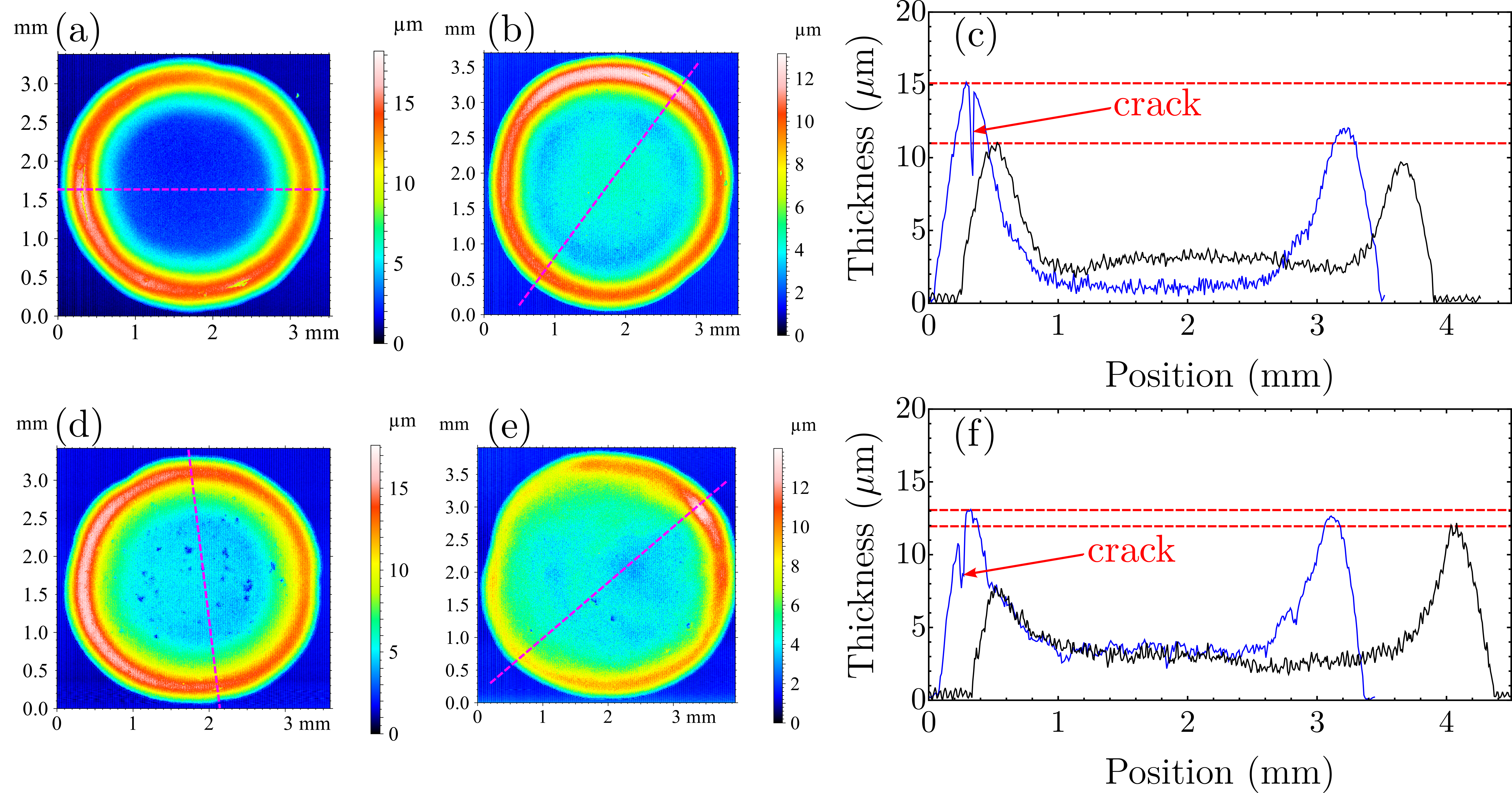
An evaporation-driven consolidating film is prone to crack to release the excess stress once the accumulated stress is beyond the critical stress . The value of can be determined by measuring the corresponding critical film thickness as 60, 61:
| (B1) |
where is the shear modulus of bacteria, and are the Young’s modulus and Poisson’s ratio of the dehydrated bacteria, is the characteristic radius, is the surface tension, is the coordination number, is the 3D packing fraction. To measure , we prepared drops of bacterial suspensions with L and various , and deposited them on glass substrates for drying to obtain dried deposits of different thicknesses.
Figure B1 shows the measurements of the height profiles along the diameters of two dried deposits of swimmer drops (Figs. B1a-c) and two dried deposits of tumbler drops (Figs. B1d-f). In both cases, cracks were initiated in the dried deposits with the larger film thickness, but not in the deposits with the smaller film thickness. The critical film thickness for cracking, , should lie between these two thicknesses. We simply took the average of the maximum values of the blue and black curves as indicated by the dashed lines in Figs. B1c and f, which gave the estimate m for swimmers and m for tumblers. Plugging the typical values of 300 MPa 37, 0.2 37 m, mN/m, , and for swimmers or for tumblers (Appendix C) into Eq. B1, we have the critical stress Pa for both swimmers and tumblers.
The critical stress for film delamination can be estimated using 62:
| (B2) |
where is the adhesion strength of the film, and are the Young’s modulus and critical delamination thickness of the film, respectively. Although it is challenging to directly measure the adhesion between an evaporation-driven consolidating bacteria film and a glass substrate, the adhesion strength for most biofilms is on the order of magnitude of 5 50, 63, 64, 65, 66, 67. Here, the Young’s modulus of the dehydrated bacteria films can be estimated as MPa. In our experiments, the film delamination and cracking developed nearly simultaneously. Therefore, we simply took m. Plugging the values of , and into Eq. B2 yields Pa for swimmer films, which is of the same order of magnitude as . Following the same analysis, of tumbler films is also the same order of magnitude at Pa.
Appendix C Estimate of the 3D packing fraction of bacteria in dried deposits
To estimate the 3D packing fraction of bacteria in a dried deposit, we first calculate the relation between the 3D packing fraction and the 2D area fraction . Assuming a cylindrical shape of a bacterial body with a length of and radius of . The volume of bacterial body is and the cross-sectional area of the body along its major axis is . Consider bacteria within a horizontal layer of length and width parallel to the substrate. We assume that all the bacteria are confined within the layer with their major axes aligned parallel to the substrate, a configuration agreeing reasonably well with our SEM images (Figs. 4 and 8). The number of bacteria within the layer is . The 2D area fraction within the layer is given by , whereas the 3D volume fraction is . Thus, . We experimentally measured for wild-type swimmers based on the SEM images (Fig. 4b), which gives . Consequently, . We note that the experimental is slightly larger than the theoretical maximum values of 3D random packing fraction of rigid cylinders () 68, 69, 70, which is likely due to the local order structure of bacteria and the approximation taken in our estimate. Similarly, we also measured the 2D area fraction of tumblers in the dried deposit, which gives . Thus, the 3D packing fraction of tumblers is: , which is smaller than the 3D packing fraction of the wild-type swimmers as expected.
References
- Schaller et al. 2010 V. Schaller, C. Weber, C. Semmrich, E. Frey and A. R. Bausch, Nature, 2010, 467, 73–77.
- Duclos et al. 2020 G. Duclos et al., Science, 2020, 367, 1120–1124.
- Guo et al. 2018 S. Guo, D. Samanta, Y. Peng, X. Xu and X. Cheng, Proc. Natl. Acad. Sci. U.S.A., 2018, 115, 7212–7217.
- Peng et al. 2021 Y. Peng, Z. Liu and X. Cheng, Sci. Adv, 2021, 7, eabd1240.
- Liu et al. 2021 Z. Liu, W. Zeng, X. Ma and X. Cheng, Soft Matter, 2021, 17, 10806–10817.
- Palacci et al. 2013 J. Palacci, S. Sacanna, A. P. Steinberg, D. J. Pine and P. M. Chaikin, Science, 2013, 339, 936–940.
- Bricard et al. 2013 A. Bricard, J.-B. Caussin, N. Desreumaux, O. Dauchot and D. Bartolo, Nature, 2013, 503, 95–98.
- Karani et al. 2019 H. Karani, G. E. Pradillo and P. M. Vlahovska, Phys. Rev. Lett., 2019, 123, 208002.
- Ramaswamy 2010 S. Ramaswamy, Annu. Rev. Conden. Matter Phys., 2010, 1, 323–345.
- Marchetti et al. 2013 M. C. Marchetti, J.-F. Joanny, S. Ramaswamy, T. B. Liverpool, J. Prost, M. Rao and R. A. Simha, Rev. Mod. Phys., 2013, 85, 1143–1189.
- Gompper et al. 2020 G. Gompper et al., J. Phys. Condens. Matter, 2020, 32, 193001.
- Saintillan and Shelley 2015 D. Saintillan and M. Shelley, in Complex Fluids in Biological Systems, ed. S. Spagnolie, Springer-Verlag, New York, 2015, pp. 319–355.
- Alert et al. 2022 R. Alert, J. Casademunt and J.-F. Joanny, Annu. Rev. Conden. Matter Phys., 2022, 13, 143–170.
- Epstein et al. 2012 A. K. Epstein, T.-S. Wong, R. A. Belisle, E. M. Boggs and J. Aizenberg, Proc. Natl. Acad. Sci. U.S.A., 2012, 109, 13182–13187.
- Hall-Stoodley et al. 2004 L. Hall-Stoodley, J. W. Costerton and P. Stoodley, Nat. Rev. Microbiol., 2004, 2, 95–108.
- Kumar and Anand 1998 C. G. Kumar and S. K. Anand, Int. J. Food Microbiol., 1998, 42, 9–27.
- Yanni et al. 2017 D. Yanni, A. Kalziqi, J. Thomas, S. L. Ng, S. Vivek, W. C. Ratcliff, B. K. Hammer and P. J. Yunker, arXiv: 1707.03472, 2017.
- Nellimoottil et al. 2007 T. T. Nellimoottil, P. N. Rao, S. S. Ghosh and A. Chattopadhyay, Langmuir, 2007, 23, 8655–8658.
- Sempels et al. 2013 W. Sempels, R. De Dier, H. Mizuno, J. Hofkens and J. Vermant, Nat. Commun., 2013, 4, 1757.
- Andac et al. 2019 T. Andac, P. Weigmann, S. K. Velu, E. Pinçe, G. Volpe, G. Volpe and A. Callegari, Soft Matter, 2019, 15, 1488–1496.
- Kasyap et al. 2014 T. Kasyap, D. L. Koch and M. Wu, Phys. Fluids, 2014, 26, 111703.
- Agrawal et al. 2020 A. Agrawal, S. Sinha, R. Mukherjee and D. Mampallil, Phys. Fluids, 2020, 32, 093308.
- Goehring et al. 2015 L. Goehring, A. Nakahara, T. Dutta, S. Kitsunezaki and S. Tarafdar, Desiccation cracks and their patterns: Formation and modelling in science and nature, John Wiley & Sons, 2015.
- Allain and Limat 1995 C. Allain and L. Limat, Phys. Rev. Lett., 1995, 74, 2981–2984.
- Dufresne et al. 2003 E. R. Dufresne, E. I. Corwin, N. Greenblatt, J. Ashmore, D. Wang, A. D. Dinsmore, J. Cheng, X. Xie, J. W. Hutchinson and D. A. Weitz, Phys. Rev. Lett., 2003, 91, 224501.
- Jing and Ma 2012 G. Jing and J. Ma, J. Phys. Chem. B, 2012, 116, 6225–6231.
- Dugyala et al. 2016 V. R. Dugyala, H. Lama, D. K. Satapathy and M. G. Basavaraj, Sci. Rep., 2016, 6, 30708.
- Lama et al. 2021 H. Lama, T. Gogoi, M. G. Basavaraj, L. Pauchard and D. K. Satapathy, Phys. Rev. E, 2021, 103, 032602.
- Domokos et al. 2020 G. Domokos, D. J. Jerolmack, F. Kun and J. Török, Proc. Natl. Acad. Sci. U.S.A., 2020, 117, 18178–18185.
- Ma et al. 2019 X. Ma, J. Lowensohn and J. C. Burton, Phys. Rev. E, 2019, 99, 012802.
- Routh 2013 A. F. Routh, Rep. Prog. Phys., 2013, 76, 046603.
- Zang et al. 2019 D. Zang, S. Tarafdar, Y. Y. Tarasevich, M. D. Choudhury and T. Dutta, Phys. Rep., 2019, 804, 1–56.
- Berg 2008 H. C. Berg, E. coli in Motion, Springer Science & Business Media, 2008.
- Griffith 1921 A. A. Griffith, Philos. Trans. R. Soc. London A, 1921, 221, 163–198.
- Biot 1941 M. A. Biot, J. Appl. Phys., 1941, 12, 155.
- Giorgiutti-Dauphiné and Pauchard 2018 F. Giorgiutti-Dauphiné and L. Pauchard, Eur. Phys. J. E, 2018, 41, 32.
- Yao et al. 1999 X. Yao, M. Jericho, D. Pink and T. Beveridge, J. Bacteriol., 1999, 181, 6865–6875.
- Kundukad et al. 2016 B. Kundukad, T. Seviour, Y. Liang, S. A. Rice, S. Kjelleberg and P. S. Doyle, Soft Matter, 2016, 12, 5718–5726.
- Even et al. 2017 C. Even, C. Marlière, J.-M. Ghigo, J.-M. Allain, A. Marcellan and E. Raspaud, Adv. Colloid Interface Sci., 2017, 247, 573–588.
- Chen et al. 2012 Y. Chen, W. Norde, H. C. van der Mei and H. J. Busscher, MBio, 2012, 3, e00378.
- Abe et al. 2011 Y. Abe, P. Polyakov, S. Skali-Lami and G. Francius, Biofouling, 2011, 27, 739–750.
- Giorgiutti-Dauphiné and Pauchard 2014 F. Giorgiutti-Dauphiné and L. Pauchard, Eur. Phys. J. E, 2014, 37, 39.
- Style et al. 2011 R. W. Style, S. S. Peppin and A. C. Cocks, J. Geophys. Res. Earth Surf., 2011, 116, F01025.
- Robinson 2014 R. K. Robinson, Encyclopedia of food microbiology, Academic Press, 2014.
- Laspidou and Aravas 2007 C. Laspidou and N. Aravas, Water Sci. Technol., 2007, 55, 447–453.
- Gan et al. 2016 T. Gan, X. Gong, H. Schönherr and G. Zhang, Biointerphases, 2016, 11, 041005.
- Kandemir et al. 2018 N. Kandemir, W. Vollmer, N. S. Jakubovics and J. Chen, Sci. Rep., 2018, 8, 10893.
- Pagnout et al. 2019 C. Pagnout, B. Sohm, A. Razafitianamaharavo, C. Caillet, M. Offroy, M. Leduc, H. Gendre, S. Jomini, A. Beaussart, P. Bauda et al., Sci. Rep., 2019, 9, 9696.
- Rmaile et al. 2013 A. Rmaile, D. Carugo, L. Capretto, X. Zhang, J. A. Wharton, P. J. Thurner, M. Aspiras, M. Ward and P. Stoodley, Wear, 2013, 306, 276–284.
- Yan et al. 2019 J. Yan, C. Fei, S. Mao, A. Moreau, N. S. Wingreen, A. Košmrlj, H. A. Stone and B. L. Bassler, Elife, 2019, 8, e43920.
- Bourrianne et al. 2021 P. Bourrianne, P. Lilin, G. Sintès, T. Nîrca, G. H. McKinley and I. Bischofberger, Soft Matter, 2021, 17, 8832–8837.
- Leang et al. 2017 M. Leang, F. Giorgiutti-Dauphine, L.-T. Lee and L. Pauchard, Soft Matter, 2017, 13, 5802–5808.
- Style and Peppin 2011 R. W. Style and S. S. Peppin, Proc. Roy. Soc. A, 2011, 467, 174–193.
- Badar and Tirumkudulu 2022 A. Badar and M. S. Tirumkudulu, Soft Matter, 2022, 18, 2252–2275.
- Di Giuseppe et al. 2012 E. Di Giuseppe, A. Davaille, E. Mittelstaedt and M. François, Rheol. Acta, 2012, 51, 451–465.
- Jagla 2002 E. Jagla, Phys. Rev. E, 2002, 65, 046147.
- Néda et al. 2002 Z. Néda, K.-t. Leung, L. Józsa and M. Ravasz, Phys. Rev. Lett., 2002, 88, 095502.
- Giorgiutti-Dauphine and Pauchard 2015 F. Giorgiutti-Dauphine and L. Pauchard, Colloids Surf., A, 2015, 466, 203–209.
- Wang 2017 H. F. Wang, Theory of linear poroelasticity with applications to geomechanics and hydrogeology, Princeton University Press, 2017.
- Tirumkudulu and Russel 2005 M. S. Tirumkudulu and W. B. Russel, Langmuir, 2005, 21, 4938–4948.
- Singh and Tirumkudulu 2007 K. B. Singh and M. S. Tirumkudulu, Phys. Rev. Lett., 2007, 98, 218302.
- Meng et al. 2020 W. Meng, M. Liu, Y. Gan, L. Pauchard and C. Chen, Eur. Phys. J. E, 2020, 43, 64.
- Chen et al. 1998 M. Chen, Z. Zhang and T. Bott, Biotechnol. Tech., 1998, 12, 875–880.
- Zhang et al. 2011 W. Zhang, A. G. Stack and Y. Chen, Colloids Surf. B: Biointerfaces, 2011, 82, 316–324.
- Dupres et al. 2005 V. Dupres, F. D. Menozzi, C. Locht, B. H. Clare, N. L. Abbott, S. Cuenot, C. Bompard, D. Raze and Y. F. Dufrêne, Nat. Methods, 2005, 2, 515–520.
- Liu et al. 2010 Y. Liu, P. A. Pinzón-Arango, A. M. Gallardo-Moreno and T. A. Camesano, Mol. Nutr. Food Res., 2010, 54, 1744–1752.
- Jiang et al. 2021 Z. Jiang, T. Nero, S. Mukherjee, R. Olson and J. Yan, Front. Microbiol., 2021, 12, 1642.
- Donev et al. 2004 A. Donev, F. H. Stillinger, P. Chaikin and S. Torquato, Phys. Rev. Lett., 2004, 92, 255506.
- Li et al. 2010 S. Li, J. Zhao, P. Lu and Y. Xie, Chi. Sci. Bull., 2010, 55, 114–119.
- Liu et al. 2018 L. Liu, Y. Yuan, W. Deng and S. Li, J. Chem. Phys., 2018, 149, 104503.