Quantifying Spin-Orbit Torques in Antiferromagnet/Heavy Metal Heterostructures
Abstract
The effect of spin currents on the magnetic order of insulating antiferromagnets (AFMs) is of fundamental interest and can enable new applications. Toward this goal, characterizing the spin-orbit torques (SOT) associated with AFM/heavy metal (HM) interfaces is important. Here we report the full angular dependence of the harmonic Hall voltages in a predominantly easy-plane AFM, epitaxial c-axis oriented -Fe2O3 films, with an interface to Pt. By modeling the harmonic Hall signals together with the -Fe2O3 magnetic parameters, we determine the amplitudes of field-like and damping-like SOT. Out-of-plane field scans are shown to be essential to determining the damping-like component of the torques. In contrast to ferromagnetic/heavy metal heterostructures, our results demonstrate that the field-like torques are significantly larger than the damping-like torques, which we correlate with the presence of a large imaginary component of the interface spin-mixing conductance. Our work demonstrates a direct way of characterizing SOT in AFM/HM heterostructures.
Recently antiferromagnetic materials have been gathering increasing attention from the spintronics community due to their advantageous properties such as fast spin dynamics, low susceptibility, and magnetic moment compensation Gomonay and Loktev (2014); Jungwirth et al. (2016); Baltz et al. (2018); Fukami et al. (2020). Detecting and manipulating antiferromagnetic order electrically is an important milestone for realizing devices based on AFMs Wadley et al. (2016); Cheng et al. (2016); Gray et al. (2019); Cheng et al. (2020); Cogulu et al. (2021). It is known that spin-orbit torques (SOT) are one of the most effective ways to manipulate magnetic order in both ferromagnets (FM) and ferrimagnets Gomonay and Loktev (2010); Cheng et al. (2014); Avci et al. (2014); Bodnar et al. (2018); Chen et al. (2018); Zhou et al. (2018); Parthasarathy et al. (2021); Shao et al. (2021); Zhu et al. (2021). However, their effectiveness is less well explored and quantified for AFMs, particularly insulating AFMs. Therefore, characterizing the type and the amplitude of the SOT is crucial for understanding and predicting AFM dynamics. An important technique to characterize SOT is harmonic Hall measurements Baldrati et al. (2018); Cheng et al. (2019). Although this technique has been used extensively in FM/heavy metal (HM) bilayers, there are few studies of AFM.
In this work, we use harmonic Hall measurements to characterize the type and amplitude of spin-orbit torques in -Fe2O3/Pt bilayer heterostructures. First, we show the full angular dependence of and harmonic Hall signal in 3 orthogonal planes.
Then, we develop a model of the response that accounts for the magnetic properties of -Fe2O3, including its magnetic anisotropy, exchange and Dzyaloshinskii-Moriya interactions (DMI), and compare the model with the experimental results. By fitting the data from six measurements together (the and harmonic response with the field rotated in three orthogonal planes), we extract the amplitudes of the damping-like and field-like torques. Surprisingly and contrary to the case of ferromagnets/heavy metal heterostructures, we find field-like torques to be significantly larger than damping-like torques. We also show that there is an ordinary Hall-effect (OHE) contribution to the response when the applied magnetic field has a component out of the film plane and spin Seebeck effect (SSE) contribution to the in-plane field results. Further, our model suggests a small canting of the easy plane of the AFM. Finally, by performing finite-element simulations, we show that Oersted fields are much smaller than the field-like SOT.
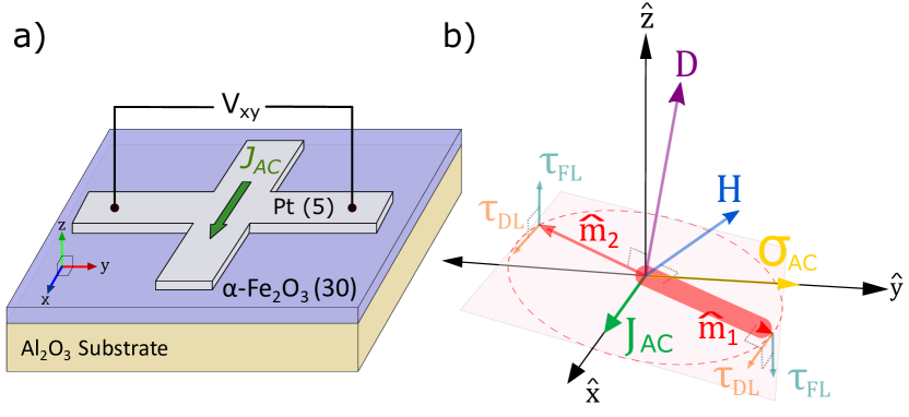
Figure 1(a) shows a schematic of the experimental configuration for the harmonic Hall measurements. We perform the measurements on 30 nm thick epitaxial c-axis oriented -Fe2O3 grown on single crystalline Al2O3 (0001) substrates at 500°C using off-axis sputtering Cheng et al. (2019, 2020). The films are capped with 5 nm thick Pt in-situ, deposited at room temperature. Finally, we pattern the Pt layer into a 5 m width and 15 m length Hall-cross structure using electron-beam lithography and Ar+ plasma etching. All measurements are done with a Quantum Design DynaCool PPMS system. An AC current with frequency 953 Hz is supplied with a Keithley 6221 current source and detected with a SRS lock-in amplifier SR830; current densities of A/m2 and A/m2 were used for 1st and 2nd harmonic measurements, respectively. All experiments were performed at 300 K.
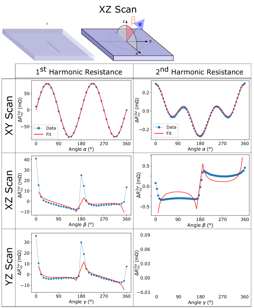
Figure 1(b) shows the geometry of the model we used to explain the experimental data. The antiferromagnet’s hard axis and DMI are represented by the same vector . The AFM sublattice moment directions are indicated by unit vectors and . The Néel vector lies in the easy plane, which is perpendicular to , indicated by the red plane. is the applied magnetic field and is the spin accumulation at the interface caused by . The resulting torques on the sublattice moments are decomposed into field-like () and damping-like components (). Notice we do not constrain to be parallel to the -axis, as canting of the easy plane in AFMs, due to the strain effects from the substrate has been reported Cogulu et al. (2021); Schmitt et al. (2021). As shown at the top of Fig. 2, the applied field is rotated in one of the three Cartesian planes: XY, XZ or YZ, where the current is in the direction and is perpendicular to the film plane.
Figure 2 shows the full angular dependence of Hall signal for both harmonics (blue points), for all three field scans, at a selected magnetic field strength of T together with the model fit (red lines). XY, XZ and YZ plane scans of magnetic field and the angles , and are shown at the top of Fig. 2. In the in-plane XY scan, both and harmonic Hall signals follows smooth trigonometric functions as we rotate the field in the sample plane. This is the expected behavior because spin-Hall magnetoresistance (SMR) and field-like torques are the main contributors in and XY scan harmonic signals, respectively. On the other hand, for out-of-plane field rotation experiments—XZ and YZ field scans—the angular dependencies do not follow a simple trigonometric function. A comprehensive model is needed in order to explain all six scans at the same time, as we discuss below.
In the sample geometry indicated in Fig. 1(b), an AC current density (with angular frequency Hz) applied in the direction generates an oscillating spin accumulation in the direction, which acts on the -Fe2O3 film through both field-like and damping-like torques. The measured Hall voltage arises from the spin-Hall magnetoresistance (SMR): , where is the cross sectional area of Pt perpendicular to the direction and the SMR has the form Chen et al. (2013); Hayashi et al. (2014); Fischer et al. (2018); Lebrun et al. (2019) (the contribution of is negligible). Since the current-induced torques only result in a slight deviation of from its equilibrium orientation, we can expand the SMR as:
| (1) | ||||
where the first term is the unperturbed SMR, the resistance response that is independent of the applied current density, which leads to the first harmonic signal . The second term, which is itself proportional to , gives rise to the second harmonic response . Therefore, to find the harmonic responses, we need to calculate . is determined by the dynamics of the Néel vector and hence by the dynamics of sublattice magnetic moments, and .
In the macrospin approximation, the free energy density (scaled into field dimensions) can be expressed in terms of the unit magnetization vectors as
| (2) |
where is the product of the vacuum permeability and the gyromagnetic ratio . and are unit vectors in the directions of the hard axis anisotropy and DMI respectively. , and are the effective fields associated with the exchange interaction, the hard axis anisotropy and the DMI, respectively. Here we have ignored the in-plane easy axis anisotropy because it is much weaker than and Lebrun et al. (2019). This simplification, however, becomes invalid when the in-plane projection of is insufficient to maintain a single domain state Cheng et al. (2019) (e.g., when is close to being perpendicular to the easy plane). The dynamics of the sublattice magnetic moments are described by the coupled Landau-Lifshitz-Gilbert-Slonczewski equations
| (3) |
where is the effective field acting on , is the Gilbert damping constant, is the Oersted field and the thickness of the Pt film. is the direction of spin accumulation (here along ), and and are the strengths of the field-like and damping-like torques, respectively.
All the three fields generated by the current are linearly proportional to . In particular, and satisfy the same symmetry, but they are distinguishable by the dependence on the Pt film thickness. Because the intrinsic frequency of the spin dynamics in -Fe2O3 is several orders of magnitude larger than Seavey (1972), we can treat as quasi-static vectors that adiabatically adjust to the AC current, remaining in the instantaneous ground state in the presence of current-induced torques. Under the adiabatic approximation, Eq. (3) can be solved analytically after a tedious derivation Zhang and Cheng , which, if , can be expressed by the Néel vector as function of and . Finally, by inserting into Eq. (1), we obtain the general solution of SMR and the first two harmonic responses and . This general solution, however, cannot be recast into a concise form unless we assume that and i.e. the easy plane coincides with the film plane without tilting). The special solution for vanishing tilt is:
| (4) | ||||
| (5) | ||||
where and are the polar and azimuthal angles of , and is a current-independent constant. In Fig. 2, we identify these angles as and for the XY scan, (or ) and (or ) for the XZ scan, and (or ) and (or ) for the YZ scan, respectively. To better fit the experimental data shown in Fig. 2, however, we further allow a small tilting of the hard axis but still assume that , which yields a complicated expression not shown here. We observe a good agreement with the experiment at a tilt angle of 3° with respect to , which is plotted by the red curves in Fig. 2. Since the model assumes , our solution breaks down at extremely large fields, which is partially reflected in Fig. 3 and discussed later.
The field-like torque and the damping-like torque play very different roles in driving the dynamics of magnetic moments. As illustrated in Fig. 1(b), the damping-like torque cants both magnetic moments towards the same in-plane direction, which will subsequently leverage the exchange torque between and so that the Néel vector develops an out-of-plane component. By contrast, the field-like torque acts as an effective field that directly drives the net magnetic moment so that the AC current induces an in-plane rotation of . Since by definition, a direct consequence is that undergoes an in-plane oscillation. Correspondingly, in the absence of tilting, damping-like torques vanish in the XY scan (°), and field-like torques vanish in YZ scan (°). However, any amount of tilting of the easy plane will prevent this vanishing and both field-like and damping-like torques will have contributions in XY and YZ scans.
Because of the small magnetic moment present in -Fe2O3 above its Morin transition, the Néel vector couples to the external magnetic field perpendicularly. The easy plane and the external field direction together are adequate to uniquely set the equilibrium direction of the Néel vector and a T in-plane component of the applied field can fully align the Néel vector to overcome any in-plane magnetic anisotropy.

We fit the experimental results with 3 free parameters: the direction of the hard axis () and the amplitudes of the spin-orbit torques ( and ). For every scan, first we fit the harmonic response, where we extract the current-independent constant (Eq. 4). This resistance is necessary to correctly extract other desired parameters from the second harmonic response (Eq. 5). Then together with the , we use material parameters from the literature 2 T, 0.01 T and T (Williamson and Foner, 1964; Mizushima and Iida, 1966; Elliston and Troup, 1968) to fit the responses with our model. These fits allow us to extract the amplitudes of effective fields associated with the spin-orbit torques per current density which are 10TA/m2) and 10TA/m2).
A slight tilting ( 3°) of the hard-axis and (again, in our model) from the -direction is needed in order to simultaneously capture the form of each and every one of the field scans. This tilt is especially crucial in 1st harmonic out-of-plane scans (XZ and YZ), where in order to get any non-zero response from our model, we need some degree of canting of the easy plane. Moreover, to explain the shape of the response, an additional cosine term is needed, which we interpret as the ordinary Hall effect response of Pt.
In our experiments, we rotate the applied magnetic field both in the film plane and out of the film plane while passing high current densities across the Pt leads. Therefore, there will be effects arising from the ordinary Hall effect induced by the perpendicular field component and from the spin Seebeck effect (SSE) due to a thermal gradient in the direction caused by Joule heating. Figure 3 summarizes how we extracted these contributions. On the left (Fig. 3(a) and (c)), we show the field dependence of 1st harmonic YZ and 2nd harmonic XY scans. And, on the right (Fig. 3(b) and (d)), we show the separated contributions of Hall effect and SSE from those scans, respectively. The field dependence of the signals can be used to isolate different contributions to the signal, as well as to show the model field dependence with the experimental results.
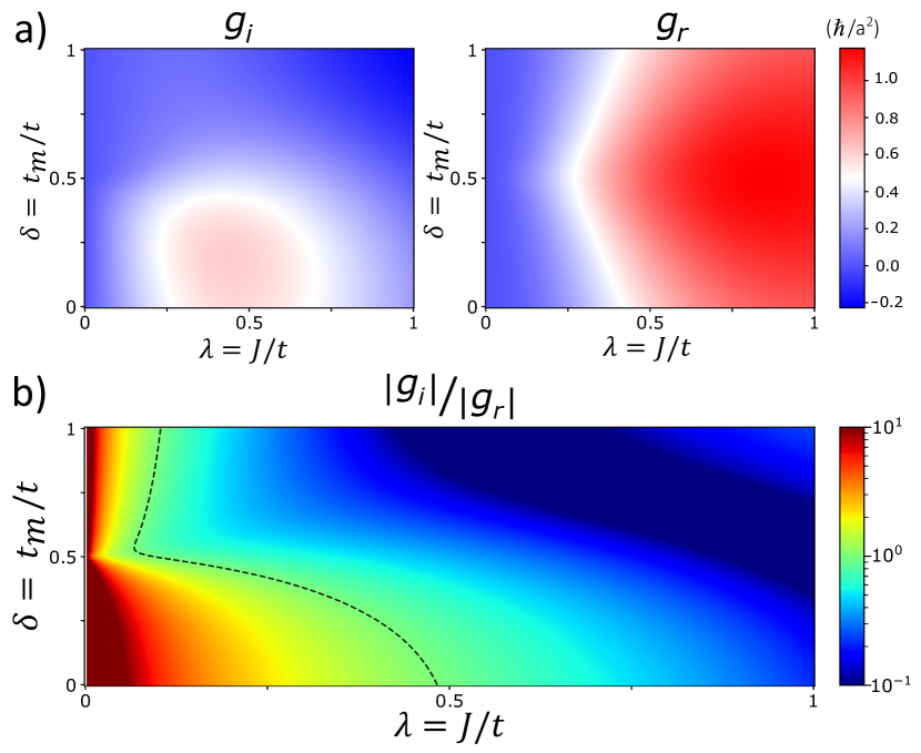
Figure 3(b) shows the Hall effect contribution in 1st harmonic and YZ scans. Since the expected Hall contribution is in the form , the linear trend with applied field supports our claim. Similarly, Fig. 3(d) shows decomposition of into two components: Field-like SOT (blue) and spin Seebeck effect (orange) . In this case, the expected signals are of the form and for field-like and SSE contributions, respectively. The form of the SSE contribution indicates that the effect is associated with the excess moment in the so called the transverse spin Seebeck geometry, in which the signal scales linearly with the applied field (Bauer et al., 2012). Furthermore, the remaining field-like component decreases with increasing applied magnetic field and follows a dependence, as in Eq. 5. We attribute the deviation from a dependence at low and high fields to the fact that our model assumptions are not valid in those limits.
Our experimental results show that the field-like torque is about two orders of magnitude larger than the damping-like torques. This implies that in the spin mixing conductance () Cheng et al. (2014)—which characterizes the interaction between itinerant electrons in the Pt and spins in the AFM—the imaginary component far exceeds the real part . This follows from the relation and (see details in Supplementary Materials). The finding is contrary to that of ferromagnetic/nonmagnetic heterostructures Tserkovnyak et al. (2002); Xia et al. (2002). To better understand this counterintuitive result, we calculate and through the interfacial spin-dependent scattering Cheng (2014), where the scattering processes depend on three parameters: the electron hopping energy in the NM (determined by the Fermi energy), the proximity-induced hopping on the AFM side, and the interfacial exchange coupling between conduction electrons in the NM and the magnetic moments in the AFM. By spin-flip scattering, electrons can deliver angular momenta to the AFM which manifests as spin torques exerting on the magnetic moments. In AFM, the Umklapp scattering is essential, which involves communications between the two magnetic sublattices, hence relying on . In Fig. 4 we plot the dependence of and on two dimensionless parameters and . Details on the calculations are discussed in the section 4 of the Supplementary Materials.
We see from Fig. 4 that regions with small and have . This ratio can become extremely large when becomes even smaller (see Supplementary Materials), which is consistent with our experimental results. Because the ratio can vary over a wide range of values depending on and , it is expected that the relative strength of the field-like and damping-like torques can vary significantly in different materials. It should be noted that the conservation of angular momentum requires , and does not violate this requirement (see the definitions of and in the Supplementary Materials). We also mention that in recent spin pumping experiments Vaidya et al. (2020); Li et al. (2020); Wang et al. (2021); Boventer et al. (2021), only could be determined because the DC component of the pumped spin current only depends on , whereas only contributes to the AC spin pumping. Our experiment, on the other hand, can directly probe the effect of .
In conclusion, we determined the type and amplitude of SOTs in antiferromagnetic -Fe2O3/Pt heterostructures by performing harmonic Hall measurements. The model we developed suggests that both in-plane and out-of-plane scans are important to accurately characterize the nature of SOTs. We also found that field-like torques are two orders of magnitude larger than damping-like torques, contrary to what has been reported in similar structures with ferromagnets. This implies that the spin-mixing conductance of the -Fe2O3/Pt interface has the unusual property of having a large imaginary component. Our work demonstrates a straightforward way to quantify SOTs and opens up a promising path for future studies on similar AFM/HM heterostructures as well as a means that can be used in optimizing SOT on AFM for applications.
Acknowledgements
This research was supported by the Air Force Office of Scientific Research under Grant FA9550- 19-1-0307. The nanostructures were realized at the Advanced Science Research Center NanoFabrication Facility of the Graduate Center at the City University of New York.
References
- Gomonay and Loktev (2014) E. V. Gomonay and V. M. Loktev, Spintronics of antiferromagnetic systems (Review Article), Low Temperature Physics 40, 17 (2014).
- Jungwirth et al. (2016) T. Jungwirth, X. Marti, P. Wadley, and J. Wunderlich, Antiferromagnetic spintronics, Nature Nanotechnology 11, 231 (2016).
- Baltz et al. (2018) V. Baltz, A. Manchon, M. Tsoi, T. Moriyama, T. Ono, and Y. Tserkovnyak, Antiferromagnetic spintronics, Rev. Mod. Phys. 90, 015005 (2018).
- Fukami et al. (2020) S. Fukami, V. O. Lorenz, and O. Gomonay, Antiferromagnetic spintronics, Journal of Applied Physics 128, 070401 (2020).
- Wadley et al. (2016) P. Wadley, B. Howells, J. Železny, C. Andrews, V. Hills, R. P. Campion, V. Novak, K. Olejnik, F. Maccherozzi, S. S. Dhesi, S. Y. Martin, T. Wagner, J. Wunderlich, F. Freimuth, Y. Mokrousov, J. Kune, J. S. Chauhan, M. J. Grzybowski, A. W. Rushforth, K. W. Edmonds, B. L. Gallagher, and T. Jungwirth, Electrical switching of an antiferromagnet, Science 351, 587 (2016).
- Cheng et al. (2016) R. Cheng, D. Xiao, and A. Brataas, Terahertz Antiferromagnetic Spin Hall Nano-Oscillator, Phys. Rev. Lett. 116, 207603 (2016).
- Gray et al. (2019) I. Gray, T. Moriyama, N. Sivadas, G. M. Stiehl, J. T. Heron, R. Need, B. J. Kirby, D. H. Low, K. C. Nowack, D. G. Schlom, D. C. Ralph, T. Ono, and G. D. Fuchs, Spin Seebeck Imaging of Spin-Torque Switching in Antiferromagnetic Pt/NiO Heterostructures, Physical Review X 9, 041016 (2019).
- Cheng et al. (2020) Y. Cheng, S. Yu, M. Zhu, J. Hwang, and F. Yang, Electrical Switching of Tristate Antiferromagnetic Néel Order in Epitaxial Films, Phys. Rev. Lett. 124, 027202 (2020).
- Cogulu et al. (2021) E. Cogulu, N. N. Statuto, Y. Cheng, F. Yang, R. V. Chopdekar, H. Ohldag, and A. D. Kent, Direct imaging of electrical switching of antiferromagnetic Néel order in epitaxial films, Phys. Rev. B 103, L100405 (2021).
- Gomonay and Loktev (2010) H. V. Gomonay and V. M. Loktev, Spin transfer and current-induced switching in antiferromagnets, Phys. Rev. B 81, 144427 (2010).
- Cheng et al. (2014) R. Cheng, J. Xiao, Q. Niu, and A. Brataas, Spin pumping and spin-transfer torques in antiferromagnets, Phys. Rev. Lett. 113, 057601 (2014).
- Avci et al. (2014) C. O. Avci, K. Garello, M. Gabureac, A. Ghosh, A. Fuhrer, S. F. Alvarado, and P. Gambardella, Interplay of spin-orbit torque and thermoelectric effects in ferromagnet/normal-metal bilayers, Phys. Rev. B 90, 224427 (2014).
- Bodnar et al. (2018) S. Y. Bodnar, L. Šmejkal, I. Turek, T. Jungwirth, O. Gomonay, J. Sinova, A. A. Sapozhnik, H.-J. Elmers, M. Kläui, and M. Jourdan, Writing and reading antiferromagnetic Mn2Au by Néel spin-orbit torques and large anisotropic magnetoresistance, Nature Communications 9 (2018).
- Chen et al. (2018) X. Z. Chen, R. Zarzuela, J. Zhang, C. Song, X. F. Zhou, G. Y. Shi, F. Li, H. A. Zhou, W. J. Jiang, F. Pan, and Y. Tserkovnyak, Antidamping-torque-induced switching in biaxial antiferromagnetic insulators, Phys. Rev. Lett. 120, 207204 (2018).
- Zhou et al. (2018) X. F. Zhou, J. Zhang, F. Li, X. Z. Chen, G. Y. Shi, Y. Z. Tan, Y. D. Gu, M. S. Saleem, H. Q. Wu, F. Pan, and C. Song, Strong Orientation-Dependent Spin-Orbit Torque in Thin Films of the Antiferromagnet Mn2Au, Phys. Rev. Applied 9, 054028 (2018).
- Parthasarathy et al. (2021) A. Parthasarathy, E. Cogulu, A. D. Kent, and S. Rakheja, Precessional spin-torque dynamics in biaxial antiferromagnets, Phys. Rev. B 103, 024450 (2021).
- Shao et al. (2021) Q. Shao, P. Li, L. Liu, H. Yang, S. Fukami, A. Razavi, H. Wu, K. Wang, F. Freimuth, Y. Mokrousov, M. D. Stiles, S. Emori, A. Hoffmann, J. Akerman, K. Roy, J.-P. Wang, S.-H. Yang, K. Garello, and W. Zhang, Roadmap of spin–orbit torques, IEEE Transactions on Magnetics 57, 1 (2021).
- Zhu et al. (2021) L. Zhu, D. C. Ralph, and R. A. Buhrman, Maximizing spin-orbit torque generated by the spin Hall effect of Pt, Applied Physics Reviews 8, 031308 (2021).
- Baldrati et al. (2018) L. Baldrati, A. Ross, T. Niizeki, C. Schneider, R. Ramos, J. Cramer, O. Gomonay, M. Filianina, T. Savchenko, D. Heinze, A. Kleibert, E. Saitoh, J. Sinova, and M. Kläui, Full angular dependence of the spin Hall and ordinary magnetoresistance in epitaxial antiferromagnetic NiO(001)/Pt thin films, Phys. Rev. B 98, 024422 (2018).
- Cheng et al. (2019) Y. Cheng, S. Yu, A. S. Ahmed, M. Zhu, Y. Rao, M. Ghazisaeidi, J. Hwang, and F. Yang, Anisotropic magnetoresistance and nontrivial spin Hall magnetoresistance in bilayers, Phys. Rev. B 100, 220408 (2019).
- Schmitt et al. (2021) C. Schmitt, L. Baldrati, L. Sanchez-Tejerina, F. Schreiber, A. Ross, M. Filianina, S. Ding, F. Fuhrmann, R. Ramos, F. Maccherozzi, D. Backes, M.-A. Mawass, F. Kronast, S. Valencia, E. Saitoh, G. Finocchio, and M. Kläui, Identification of Néel Vector Orientation in Antiferromagnetic Domains Switched by Currents in Thin Films, Phys. Rev. Applied 15, 034047 (2021).
- Chen et al. (2013) Y.-T. Chen, S. Takahashi, H. Nakayama, M. Althammer, S. T. B. Goennenwein, E. Saitoh, and G. E. W. Bauer, Theory of spin Hall magnetoresistance, Phys. Rev. B 87, 144411 (2013).
- Hayashi et al. (2014) M. Hayashi, J. Kim, M. Yamanouchi, and H. Ohno, Quantitative characterization of the spin-orbit torque using harmonic Hall voltage measurements, Phys. Rev. B 89, 144425 (2014).
- Fischer et al. (2018) J. Fischer, O. Gomonay, R. Schlitz, K. Ganzhorn, N. Vlietstra, M. Althammer, H. Huebl, M. Opel, R. Gross, S. T. B. Goennenwein, and S. Geprägs, Spin Hall magnetoresistance in antiferromagnet/heavy-metal heterostructures, Phys. Rev. B 97, 014417 (2018).
- Lebrun et al. (2019) R. Lebrun, A. Ross, O. Gomonay, S. A. Bender, L. Baldrati, F. Kronast, A. Qaiumzadeh, J. Sinova, A. Brataas, R. A. Duine, and M. Kläui, Anisotropies and magnetic phase transitions in insulating antiferromagnets determined by a Spin-Hall magnetoresistance probe, Communications Physics 2, 50 (2019).
- Seavey (1972) M. Seavey, Acoustic resonance in the easy-plane weak ferromagnets and , Solid State Communications 10, 219 (1972).
- (27) H. Zhang and R. Cheng, Theory of Harmonic Hall Responses in Spin-Torque Driven Antiferromagnets, submitted for publication, 12/2021 .
- Williamson and Foner (1964) S. J. Williamson and S. Foner, Antiferromagnetic Resonance in Systems with Dzyaloshinsky-Moriya Coupling; Orientation Dependence in , Phys. Rev. 136, A1102 (1964).
- Mizushima and Iida (1966) K. Mizushima and S. Iida, Effective in-plane anisotropy field in , Journal of the Physical Society of Japan 21, 1521 (1966).
- Elliston and Troup (1968) P. R. Elliston and G. J. Troup, Some antiferromagnetic resonance measurements in -Fe2O3, Journal of Physics C Solid State Physics 1, 169 (1968).
- Bauer et al. (2012) G. E. W. Bauer, E. Saitoh, and B. J. van Wees, Spin caloritronics, Nature Materials 11, 391 (2012).
- Tserkovnyak et al. (2002) Y. Tserkovnyak, A. Brataas, and G. E. Bauer, Spin pumping and magnetization dynamics in metallic multilayers, Physical Review B 66, 224403 (2002).
- Xia et al. (2002) K. Xia, P. J. Kelly, G. Bauer, A. Brataas, and I. Turek, Spin torques in ferromagnetic/normal-metal structures, Physical Review B 65, 220401 (2002).
- Cheng (2014) R. Cheng, Aspects of antiferromagnetic spintronics, Ph.D. thesis, The University of Texas at Austin (2014).
- Vaidya et al. (2020) P. Vaidya, S. A. Morley, J. van Tol, Y. Liu, R. Cheng, A. Brataas, D. Lederman, and E. Del Barco, Subterahertz spin pumping from an insulating antiferromagnet, Science 368, 160 (2020).
- Li et al. (2020) J. Li, C. B. Wilson, R. Cheng, M. Lohmann, M. Kavand, W. Yuan, M. Aldosary, N. Agladze, P. Wei, M. S. Sherwin, et al., Spin current from sub-terahertz-generated antiferromagnetic magnons, Nature 578, 70 (2020).
- Wang et al. (2021) H. Wang, Y. Xiao, M. Guo, E. Lee-Wong, G. Q. Yan, R. Cheng, and C. R. Du, Spin Pumping of an Easy-Plane Antiferromagnet Enhanced by Dzyaloshinskii–Moriya Interaction, Phys. Rev. Lett. 127, 117202 (2021).
- Boventer et al. (2021) I. Boventer, H. T. Simensen, A. Anane, M. Kläui, A. Brataas, and R. Lebrun, Room-temperature antiferromagnetic resonance and inverse spin-Hall voltage in canted antiferromagnets, Physical Review Letters 126, 187201 (2021).