A new flavor of correlation and superconductivity in small twist-angle trilayer graphene
When layers of graphene are rotationally misaligned by the magic angle, the moiré superlattice features extremely flat bands. Due to the enhanced density of states, the Coulomb interaction induces a variety of instabilities. The most prominent occur at integer filling and are therefore commonly attributed to spontaneous polarization of the moiré unit cell’s ‘flavor’ degrees of freedom—spin, valley, and the flat-band degeneracy. As the dominant member of the hierarchy, these correlated states are thought to crucially determine further instabilities at lower energy scales, such as superconductivity and weaker incompressible states at fractional filling. In this work, we examine the behavior of twisted trilayer graphene in a window of twist angle around , well below the expected magic angle of . In this small twist angle regime, we find surprisingly narrow bands, which are populated with both an abundance of correlation-driven states at fractional filling as well as robust superconductivity. The absence of linear-in- resistivity without significant reduction of the superconducting transition temperature, provides insights into the origin of both phenomena. Most remarkably, the hierarchy between integer and fractional filling is absent, indicating that flavor polarization does not play a governing role. The prominence of fractional filling in the small twist angle regime also points towards a longer-range effective Coulomb interaction. Combined, our results shed new light on outstanding questions in the field, while establishing the small twist angle regime as a new paradigm for exploring novel flavors of moiré physics.
The interplay of the narrow bandwidth near the magic angle of twisted graphene systems and the Coulomb interaction can give rise to the spontaneous polarization of the internal flavor degrees of freedom of the moiré unit cell, given by spin, valley, and the two almost degenerate conduction and valence flat bands. Different forms of this flavor polarization are believed to explain many emergent correlated phenomena in these systems, such as correlated insulators Lu et al. (2019); Cao et al. (2018a); Yankowitz et al. (2019), orbital ferromagnets Sharpe et al. (2019); Serlin et al. (2019); Chen et al. (2021); Polshyn et al. (2020); Lin et al. (2022), cascade of band resets Park et al. (2021b); Zondiner et al. (2020); Wong et al. (2020); Kang et al. (2021), resets in the Hall density, and saw tooth patterns in electronic compressibility Park et al. (2021b); Rozen et al. (2020); Saito et al. (2021); Liu et al. (2021a). The dominance of flavor polarization is also consistent with the hierarchical behavior at the magic angle: the most prominent correlation-driven phases appear at integer fillings Cao et al. (2018a, b); Liu et al. (2020); Cao et al. (2020a); Chen et al. (2021); Polshyn et al. (2020); Park et al. (2021a); Hao et al. (2021), whereas quantum phases at incommensurate fillings tend to be weaker Xie et al. (2021); Pierce et al. (2021). This hierarchy suggests that the Coulomb interaction leaves the translational symmetry of the moiré superlattice unbroken, which can be understood, at least phenomenologically, by electronic correlations on the length scale of one moiré wavelength. Importantly, the hierarchy likely also crucially affects the superconducting state as can be seen, e.g., in twisted trilayer graphene (tTLG) where the superconducting region in the phase diagram tracks features in the normal-state Hall density Park et al. (2021a); Hao et al. (2021).
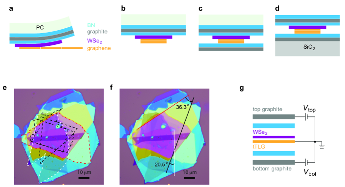
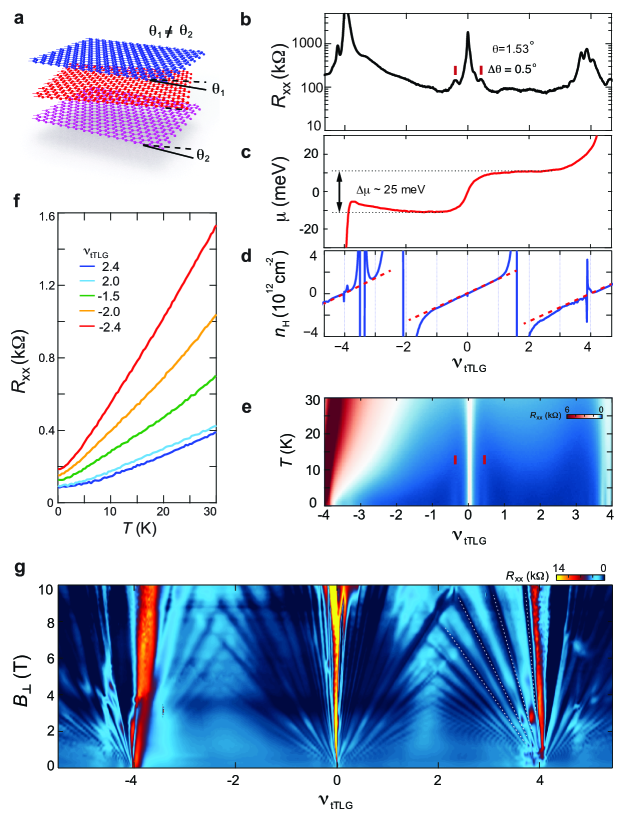
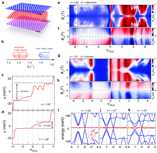
In this work, we investigate mirror-symmetric tTLG (Fig. 1a) in the small twist angle regime and uncover very flat bands in multiple samples in the twist angle range of to (Fig. 1b, see Table 2 for the list of samples studied), with bandwidth even smaller than that of our samples close to the magic angle. For simplicity, we will refer to this range of twist angle as the small twist angle regime (Fig. 1b). In this regime, we report a series of robust fractional filling correlated states, providing evidence for a longer-ranged Coulomb interaction, with electronic correlations occurring on the length scale of multiple moiré wavelengths; notably the aforementioned hierarchy between integer and fractional filling is absent. We will examine the role of longer-ranged Coulomb interaction and of the absence of hierarchy on the phenomenology of tTLG by studying transport responses of correlation-driven phases and superconductivity. We will focus our discussion here on the twist angle dependence and transport behaviors which are mostly insensitive to the presence of the atomic interface between tTLG and a thin crystal of tungsten diselenide (WSe2). The influence of the tTLG/WSe2 interface, on the other hand, will be discussed elsewhere.
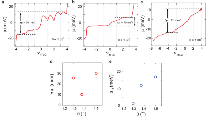
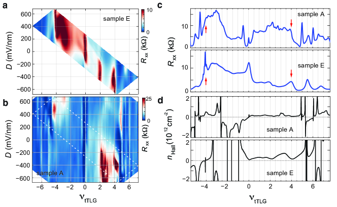
The remarkably small bandwidth of the primary moiré bands in the small twist angle regime away from the magic angle is revealed using chemical potential measurements. Fig. 1c and d plot the evolution of across the primary moiré band at and , respectively. The net increase of between moiré filling of offers an experimental definition for the moiré bandwidth. Interestingly, the moiré bandwidth is less than meV in the small twist angle regime, which is much smaller compared to the value of meV near the magic angle. Despite the flat energy band in the small twist angle regime, however, appears mostly featureless across the moiré energy band. This is in stark contrast compared to the saw tooth pattern in observed at (Fig. 1c). Since this saw tooth pattern is directly linked to spontaneous flavor polarization Park et al. (2021b); Zondiner et al. (2020); Wong et al. (2020); Kang et al. (2021), the absence of such pattern suggests that the dominant correlated features of the system are not captured by the common picture of flavor polarization at integer fillings.
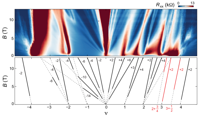
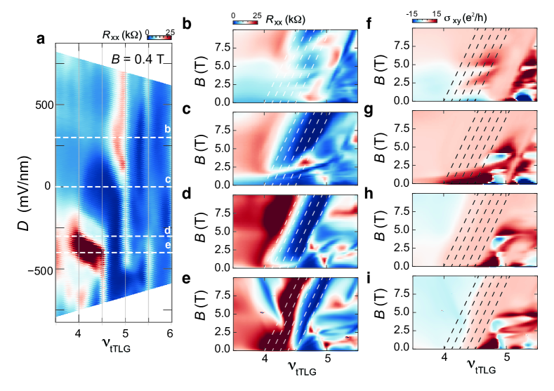
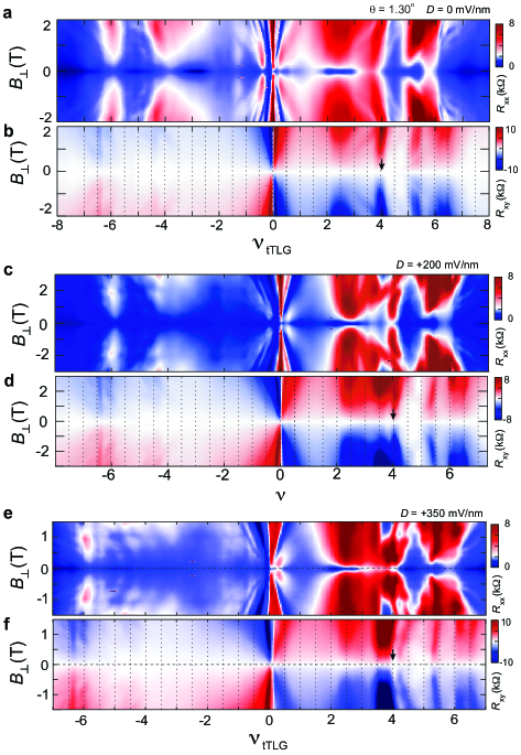
Magnetotransport data offer more insights. The magnetotransport response in the small twist angle regime, as shown in Fig. 1e-f, exhibits a series of features in both the primary and remote bands with density modulation of fractional moiré filling. This is different from the magic angle regime where correlation-driven phases appear at every integer filling. The -dependence of magnetotransport response allows us to make an interesting observation regarding the underlying band structure. Near the magic angle, magnetotransport exhibits a sharply defined transition in (Fig. 1g-h), which arises from the coexistence between a flat moiré band and a highly dispersive Dirac band. At small , transport behavior is dominated by the dispersive Dirac band, which gives rise to a series of extra Landau levels emanating from the charge neutrality point (blue features in Fig. 1g which are almost horizontal). These Dirac band Landau levels disappear when the Landau gap of the Dirac band exceeds the bandwidth of the flat band at roughly T. Notably, this transition offers another measure of the moiré bandwidth, , which is nicely consistent with the measured bandwidth in Fig. 1c (see Method section for more detailed discussion). On the high-field side of the transition, transport response is dominated by correlation-driven phases in the flatband, which are demonstrated by a series of vertical features that emerge at integer fillings Park et al. (2021b). This -induced transition is missing in the small twist angle regime, as shown in Fig. 1e-f, suggesting that the band structure is modified compared to that of the magic angle. The resulting band structure in the small twist angle regime cannot be viewed as a combination of flat moiré band and a dispersive Dirac band.
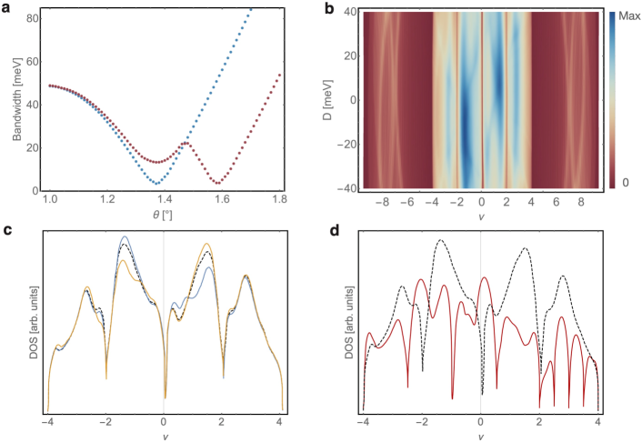
A continuum model description, which is the trilayer analog of Ref. Bistritzer and MacDonald (2011), offers a framework to understand the small bandwidth and magnetotransport response in the small twist angle regime. In this model, the key parameters determining the twist-angle dependence of the band structure are the intra- () and inter-sublattice () tunneling strengths. For , one finds a sharp minimum of the bandwidth as a function of . The band structure for the frequently used value Bistritzer and MacDonald (2011) is shown in Fig. 1i, which exhibits a minimum bandwidth near the magic angle. This is consistent with previous observations where strong Coulomb correlation near the magic angle leads to a cascade of flavor symmetry breaking at integer filling Park et al. (2021a); Hao et al. (2021); Liu et al. (2021a). With these parameters, however, the bandwidth in the small twist angle regime would be much larger than that in Fig. 1d. One way to reconcile this is to assume that decreases significantly with the twist angle since the magic angle is approximately proportional to . Another, more natural, explanation is based on using a reduced , which is known Carr et al. (2019) to describe relaxation effects. While in reality also depends on the twist angle, already a fixed gives rise to minima in the bandwidth at the magic angle and in the small twist angle regime (see Fig. S4a in SI ). The band structures calculated using a reduced ratio of at and are shown in Fig. 1j and k, respectively. According to the model, the primary moiré bands, highlighted in red, remains relatively flat in the small twist angle regime. Notably, Fig. 1j and k exhibit an extra band crossing between the remote and primary bands at the point, which is less dispersive compared to the Dirac band at the point of the Brillouin zone and becomes increasingly flat with decreasing twist angle. The presence of the less dispersive crossing at the point can explain the suppression of the Landau level features associated with the Dirac band in Fig. 1e-f. At the same time, the model indicates that some of the remote bands become less dispersive with decreasing twist angle, making it possible to host correlation-driven phases. Moreover, the energy separation between the primary and the increasingly flat remote bands is shown to be reduced at small twist angle. The energetic proximity of a band with high density of states is likely going to alter the form and impact of the Coulomb interactions in the system, as we will see below.
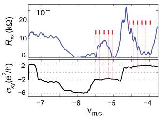
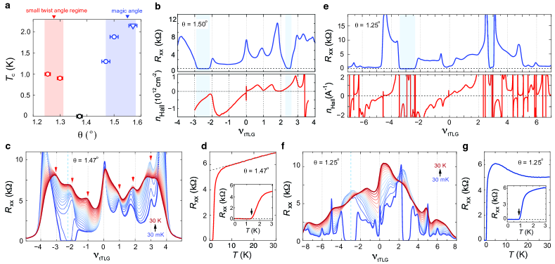
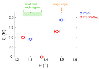
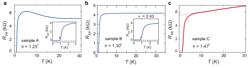
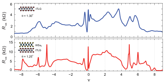
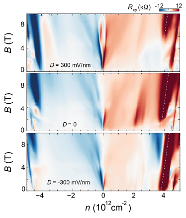
Having discussed the main phenomenology associated with the energy band structure in the small twist angle regime, we are now in position to discuss their influence on superconductivity. Despite the absence of fermi surface reconstruction, superconductivity is stable in the small twist angle regime, with transition temperature similar to previous observations near the magic angle (Fig. 2a) Park et al. (2021a); Hao et al. (2021); Liu et al. (2021a). We will show that transport behaviors associated with the superconducting phase in the small twist angle regime are distinct compared to previous observations near the magic angle, which highlights the possibility of a new superconducting phase. Published experimental literature studying magic-angle graphene moiré systems linked the superconducting phase to several transport responses arising from fermi surface reconstruction at low temperature and fluctuating flavor moments at high temperature Park et al. (2021b); Rozen et al. (2020); Saito et al. (2021); Liu et al. (2021a). This can also be seen in our data in Fig. 2b for close to the magic angle: the superconducting phase is associated with a fermi surface reconstructed by flavor polarization, which is evidenced by the apparent reset in the Hall density at . The tendency to spontaneously polarize some flavor degrees of freedom also gives rise to strong fluctuations in local moments at high temperature. This is manifested in a series of resistance peaks at every integer filling (marked by red vertical arrows in Fig. 2c). Local moments persist to around K, roughly the same scale as the Coulomb interaction near the magic angle Saito et al. (2021). In the small twist angle regime, however, the influence of flavor polarization is substantially suppressed. At low temperature, the superconducting phase is not accompanied by Hall density resets (Fig. 2e). Instead, a series of vHSs with diverging density of states is observed in the density range of the superconducting phase. This is in stark contrast with previous observations near the magic angle, where superconductivity is shown to diminish near van Hove singularities (vHSs) Park et al. (2021a). At high temperature, the longitudinal resistance evolves monotonically as the sample is tuned away from the charge neutrality point. The lack of density modulation with a periodicity of one moiré filling, as shown in Fig. 2f, provides further confirmation that the local flavor moment is suppressed in the small twist angle regime.
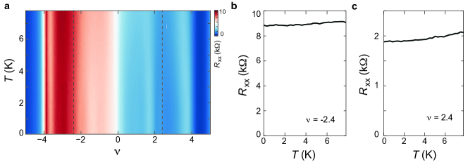
It is also worth pointing out that the linear-in-T dependence of is absent in the small twist angle regime over the entire superconducting density range. Fig. 2g shows that longitudinal resistance decreases monotonically with increasing temperature, which is in stark contrast with the linear-in-T behavior that has been universally linked with superconductivity in magic-angle graphene moiré systems (Fig. 2d and Fig. S3) Cao et al. (2020b); Jaoui et al. (2021); Polshyn et al. (2019). Our finding, therefore, suggests that the origin of superconductivity in the small twist angle regime is decoupled from the mechanism underlying the linear-in-T temperature dependence of . At the same time, the comparison between different twist angle regimes offers new insights into the linear-in-T behavior. We first note that the transition temperature of the superconducting phase is mostly insensitive to twist angle, despite significantly altered band structure (inset of Fig. 2d and g). If we assume that superconductivity comes from electron-phonon pairing or is at least crucially stabilized by it Liu et al. (2021b, a), the approximately identical indicates that the electron-phonon coupling is roughly the same. As such, the absence of the linear-in- resistance in the small twist angle regime suggests that the said phenomenon does not come from electron-phonon coupling alone Polshyn et al. (2019). Together with our observation of suppressed flavor polarization in the small twist angle regime, a natural interpretation is that the linear-in-T behavior arises from the fluctuation of flavor moments at high temperature Saito et al. (2021).
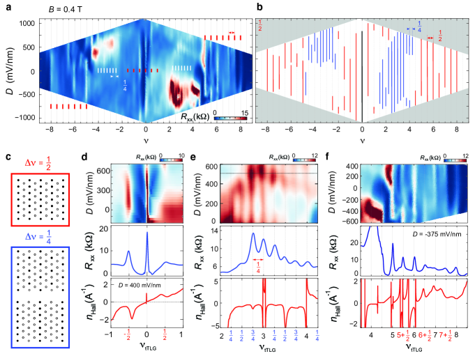
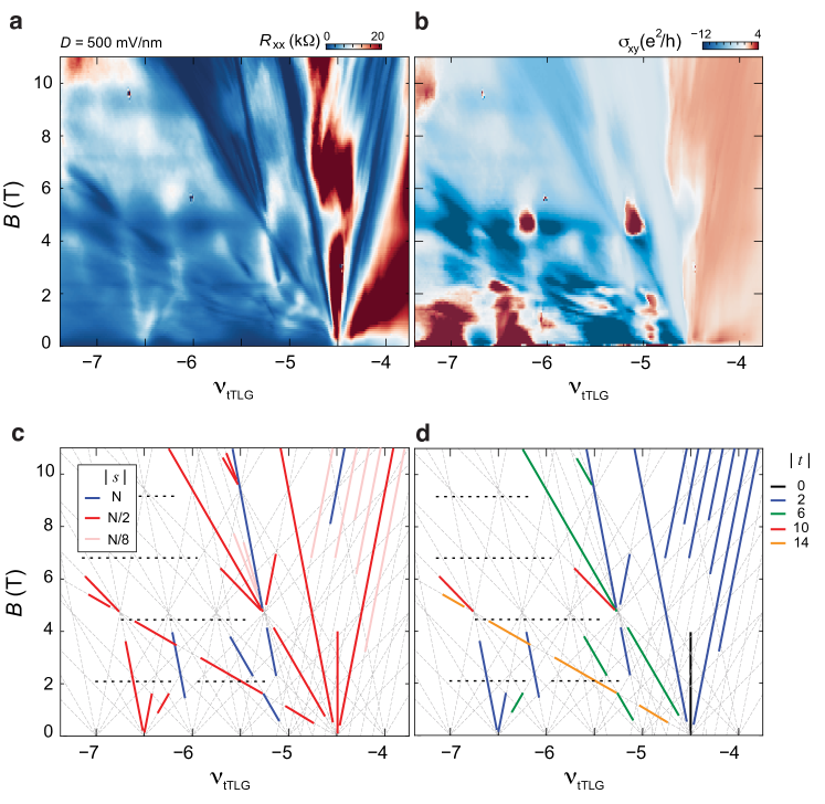
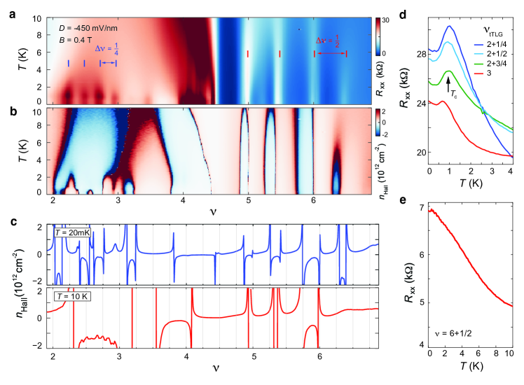
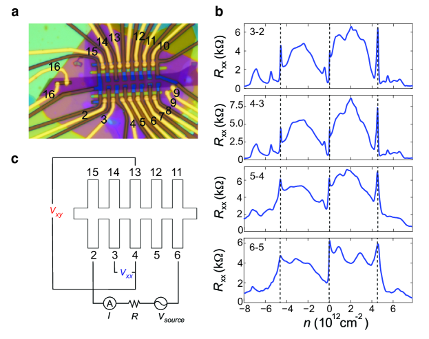
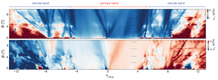
The suppression of flavor polarization offers strong indication that the form of Coulomb interaction has been altered significantly in the small twist angle regime compared to the magic angle. In the following we will investigate the nature of Coulomb interaction by studying the behavior of correlation-driven phases in the small twist angle regime. We will suppress the influence of the superconducting phase using a small external magnetic field and focus on sample A (see Table 2). In the - plane of sample A at , longitudinal resistance exhibits a series of peaks at partial band filling (Fig. 3a). The positions of the most pronounced peaks are labeled in the schematic - phase diagram in Fig. 3b. Without using any fitting parameters, all resistance peaks in the - phase diagram, across both the flat and remote bands, are shown to match integer multiples of or moiré fillings. The density modulation of fractional moiré filling points towards spontaneously breaking the moiré translation symmetry and the formation of density wave (DW) instabilities Xu et al. (2020); Xie et al. (2021), which are driven by long-range Coulomb correlations. For simplicity, we will refer to these DW states according to the periodicity of their emergence as a function of , e.g., the blue and red solid lines in Fig. 3b represent and DW states, respectively.
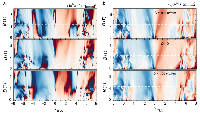
The broken moiré translation symmetry is also reflected by the Hofstadter butterfly spectrum, where high symmetry points in the recursive structure of the Hofstadter butterfly spectrum is demonstrated by horizontal features of maximum in longitudinal conductance and sign-reversals in Hall conductance (Fig. S7 and Fig. S11) Dean et al. (2013); Hunt et al. (2013); Ponomarenko et al. (2013). The most pronounced horizontal feature occurs around T, which corresponds to half a magnetic flux every four moiré unit cells, . Here is the magnetic flux per moiré unit cell, and is the magnetic flux quantum. This is in excellent agreement with the periodicity of the correlated states, which show density modulation of , and moiré filling (see Fig. 3c, Fig. S14, and Fig. S13) SI . In addition, the presence of these high symmetry points throughout the entire density range in the - plane (Fig. 3) offers strong evidence that the moiré wavelength and twist angle are well-defined throughout the uniform sample.
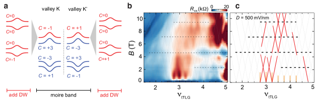
Theoretically, the emergence of 1/4 (1/2) DW order, with spatial modulation illustrated on the triangular lattice in Fig. 3c, should lead to a complex reconstruction of the moiré bands into 4 (2) sub bands each, splitting the van Hove singularity (vHs) of the unreconstructed band into multiple peaks (see SI 3 and Fig. S4d SI for a demonstration). Fig. 4a illustrates one of the possible scenarios for splitting moiré bands into DW sub bands, where one of the sub bands inherits the Chern number of the original spin-orbit-split Lin et al. (2022) bands. The formation of DW sub bands is expected to induce complex signatures in the -dependence of the Hall density , which we indeed observe: at , resistance peaks are accompanied by resets in Hall density, where diminishes at the onset of DW order (Fig. 3d). The fact that the density of mobile charge carriers is suddenly reduced is indicative of, at least, a partial gap opening in the Brillouin zone due to DW order. At higher densities, we also observe multiple vHs-like features in with diverging density of states (Fig. 3e-f). A more direct demonstration of the DW-induced band reconstruction is provided by the behavior of incompressible states in the presence of a perpendicular magnetic field. Linearly-dispersing incompressible states in the quantum Hall effect regime can be classified using a pair of quantum numbers () from the Diophantine equation , where is the filling factor at the incompressible state Xie et al. (2021); Spanton et al. (2018). According to the Streda formula, the slope is equal to the state’s Chern number, Streda (1982), and describes the moiré filling of the low-field DW state from which the incompressible state develops. In this format, incompressible states in the density range of are described by , where and take integer values. While at first sight the distribution of the Chern numbers in Fig. 4b seems inconsistent with the presence of DW states with at every , we note that can be ensured by coherently occupying two DW bands with opposite valley indices, see SI 3 SI . The emergence of additional fans at with , defining symmetry-broken Chern insulators (SBCIs), provides further confirmation that new Fermi surfaces form at every filling.
Most interestingly, correlation-driven phases in the small twist angle regime, including DW and SBCI, demonstrate a unique hierarchical behavior. For instance, in the density range near half-filling of the moiré band, correlation-driven phases with fractional and integer value of show similar transport responses (Fig. 3e and Fig. 4b). This is distinct compared to the behavior near the magic angle, where the most prominent phases develop at integer values of Pierce et al. (2021); Xu et al. (2020); Xie et al. (2021). The lack of hierarchy provides another strong indication that flavor symmetry breaking is not the dominant phenomenon governing the system’s phase diagram.
Combined together, our findings shed light on a new flavor of correlation-driven phases and superconductivity in the small twist angle regime. The key to understand the distinct behaviors in different twist angle regimes lies in the influence of the modified band structure and the origin of longer-range Coulomb correlation. Near the magic angle, the measured bandwidth value, meV, is likely enhanced by Coulomb-driven fermi surface reconstruction whereas the unreconstructed band is much narrower. On the other hand, since flavor symmetry breaking and fermi surface reconstruction are absent in the small twist angle regime, the measured bandwidth of meV is likely much closer to the non-interacting value. As such, the bare moiré bands may be more dispersive in the small twist angle regime compared to the magic angle. As the bands become more dispersive, it is natural to expect that the Coulomb interaction experiences less metallic screening and becomes longer-ranged. Following this, we argue that our findings are consistent with an intermediate regime in twist angle/band dispersion whereby correlated phases are stable, yet electronic correlations occur on the length scale of multiple moiré wavelengths, stabilizing an abundance of DW and SBCI phases across the primary and remote moiré bands. Together with the observation of the zero-field superconducting diode effect Lin et al. (2021); Scammell et al. (2021) in tTLG below the magic angle, this establishes the small twist angle regime as a promising novel playground for exotic many-body physics.
I Method
tTLG samples: Five separate samples are studied in this work, which all contain mirror symmetric tTLG. We list their twist angle, geometry and the transition temperature of the superconducting phase in Table 2. In sample A, C and E, a few-layer WSe2 crystal is stacked on top of tTLG, whereas tTLG in sample B and D are fully encapculated by hexagonal boron nitride crystals and the heterestructures do not contain WSe2. In all samples, tTLG and the hBN substrate are maximally misaligned to minimize the influence of the hexagonal boron nitride (hBN) substrate (see Fig. S17) SI .
| Sample | WSe2 | (K) | |
|---|---|---|---|
| A | ✓ | ||
| B | ✗ | ||
| C | ✓ | ||
| D | ✗ | ||
| E | ✓ | (no superconductivity) |
Bandwidth calculated based on magnetotransport data: For a Dirac band, the Landau level gap near the CNP is defined as . When exceeds the bandwidth of the moiré band, there are no free charge carriers in the Dirac band and transport response is dominated by the moiré flatband. As a result, the magnetic field value where the influence of the Dirac band disappears provides a characterization for the moiré bandwidth. For instance, Fig. 1g-h show that a -field induced transition at occurs at T, which corresponds to a bandwidth of , in excellent agreement with the chemical potential measurement in Fig. 1c.
Twist angle mismatch: we address possible relations to twist angle mismatch between top/middle and middle/bottom graphene layers in our tTLG sample. While a reconstruction of the moiré bands could theoretically be induced by a moiré pattern of moiré unit cells, resulting from a fine-tuned twist-angle mismatch between the top and bottom graphene layers Turkel et al. (2021), we believe that this scenario provides a much less natural interpretation of our findings than interaction-induced DW instabilities.
First, in the presence of a small twist angle mismatch between top and bottom graphene layers, transport responses of tTLG samples, such as Hall density and magnetoresistance, can be well explained with a single particle picture, as shown in Fig. S19. In these samples, the small twist angle mismatch gives rise to two weak satellite peaks near the charge neutrality point (marked by vertical red lines in Fig. S19b), which are the only identifiable resistance features within the moiré band (). The twist angle mismatch can be identified using these resistance peaks. Notably, superconductivity is always suppressed in the presence of twist angle mismatch in tTLG samples, as shown in Fig. S19e-f. These behaviors are in stark contrast with our observations in the small twist angle regime.
Second, unlike moiré-induced band reconstruction which will give rise to an approximately temperature independent gap, the vHSs associated with 1/4 DW states disappear with increasing temperature at K (Supplemental Fig. S15) SI . This points towards a Coulomb-driven origin. In a separate work Lin et al. (2021), we show that superconductivity is stabilized in this sample at . If twist angle mismatch gave rise to a 4-fold enlarged moiré supercell, superconductivity would be expected to exhibit a density modulation with filling periodicity. However, despite the emergence of superconductivity in regions of the - phase diagram where DW states are present at small magnetic fields, its robustness is largely insensitive to the density modulation.
Finally, a density modulation of and filling has been observed in all samples with twist angles spanning a range of to degrees SI , suggesting that density wave instability is common for tTLG samples. An accidental twist angle mismatch is unlikely to yield such reproducibility. This is further supported by the following observations: (i) the location of all correlated insulators throughout the density range is accurately matched with integer multiple of and without any fitting parameter; (ii) a high symmetry point in the Hofstadter spectrum is observed at over the full density range. These observations highlights a well-defined moiré wavelength and excellent homogeneity of the tTLG sample, whereas a twist angle mismatch is known to give rise to sample inhomogeneity Turkel et al. (2021).
Combined, our findings suggest that the insulating phases at fractional fillings are correlation-driven DW instabilities, which are intrinsic to the tTLG/WSe2 heterostructure, rather than a result of twist-angle mismatch.
Acknowledgments
J.I.A.L and J.L are supported by NSF DMR-2143384. P.S. acknowledges support from the Brown University Undergraduate Teaching and Research Awards. Device fabrication was performed in the Institute for Molecular and Nanoscale Innovation at Brown University. H. D. Scammell acknowledges funding from ARC Centre of Excellence FLEET. K.W. and T.T. acknowledge support from the Elemental Strategy Initiative conducted by the MEXT, Japan (Grant Number JPMXP0112101001) and JSPS KAKENHI (Grant Numbers 19H05790, 20H00354 and 21H05233).
References
- (1) Please see the supplementary materials .
- Park et al. (2021a) J. M. Park, Y. Cao, K. Watanabe, T. Taniguchi, and P. Jarillo-Herrero, Nature 590, 249 (2021a).
- Lu et al. (2019) X. Lu, P. Stepanov, W. Yang, M. Xie, M. A. Aamir, I. Das, C. Urgell, K. Watanabe, T. Taniguchi, G. Zhang, A. Bachtold, A. H. MacDonald, and D. K. Efetove, arXiv preprint arXiv:1903.06513 (2019).
- Cao et al. (2018a) Y. Cao, V. Fatemi, A. Demir, S. Fang, S. L. Tomarken, J. Y. Luo, J. D. Sanchez-Yamagishi, K. Watanabe, T. Taniguchi, E. Kaxiras, R. C. Ashoori, and P. Jarillo-Herrero, Nature 556, 80 (2018a).
- Yankowitz et al. (2019) M. Yankowitz, S. Chen, H. Polshyn, Y. Zhang, K. Watanabe, T. Taniguchi, D. Graf, A. F. Young, and C. R. Dean, Science 363, 1059 (2019).
- Sharpe et al. (2019) A. L. Sharpe, E. J. Fox, A. W. Barnard, J. Finney, K. Watanabe, T. Taniguchi, M. Kastner, and D. Goldhaber-Gordon, arXiv preprint arXiv:1901.03520 (2019).
- Serlin et al. (2019) M. Serlin, C. Tschirhart, H. Polshyn, Y. Zhang, J. Zhu, K. Watanabe, T. Taniguchi, L. Balents, and A. Young, arXiv preprint arXiv:1907.00261 (2019).
- Chen et al. (2021) S. Chen, M. He, Y.-H. Zhang, V. Hsieh, Z. Fei, K. Watanabe, T. Taniguchi, D. H. Cobden, X. Xu, C. R. Dean, and M. Yankowitz, Nature Physics 17, 374 (2021).
- Polshyn et al. (2020) H. Polshyn, J. Zhu, M. Kumar, Y. Zhang, F. Yang, C. Tschirhart, M. Serlin, K. Watanabe, T. Taniguchi, A. MacDonald, and A. F. Young, Nature 588, 66 (2020).
- Lin et al. (2022) J.-X. Lin, Y.-H. Zhang, E. Morissette, Z. Wang, S. Liu, D. Rhodes, K. Watanabe, T. Taniguchi, J. Hone, and J. Li, Science 375, 437 (2022).
- Park et al. (2021b) J. M. Park, Y. Cao, K. Watanabe, T. Taniguchi, and P. Jarillo-Herrero, Nature 592, 43 (2021b).
- Zondiner et al. (2020) U. Zondiner, A. Rozen, D. Rodan-Legrain, Y. Cao, R. Queiroz, T. Taniguchi, K. Watanabe, Y. Oreg, F. von Oppen, A. Stern, et al., Nature 582, 203 (2020).
- Wong et al. (2020) D. Wong, K. P. Nuckolls, M. Oh, B. Lian, Y. Xie, S. Jeon, K. Watanabe, T. Taniguchi, B. A. Bernevig, and A. Yazdani, Nature 582, 198 (2020).
- Kang et al. (2021) J. Kang, B. A. Bernevig, and O. Vafek, arXiv preprint arXiv:2104.01145 (2021).
- Rozen et al. (2020) A. Rozen, J. M. Park, U. Zondiner, Y. Cao, D. Rodan-Legrain, T. Taniguchi, K. Watanabe, Y. Oreg, A. Stern, E. Berg, et al., arXiv preprint arXiv:2009.01836 (2020).
- Saito et al. (2021) Y. Saito, F. Yang, J. Ge, X. Liu, T. Taniguchi, K. Watanabe, J. Li, E. Berg, and A. F. Young, Nature 592, 220 (2021).
- Liu et al. (2021a) X. Liu, K. Watanabe, T. Taniguchi, and J. Li, arXiv preprint arXiv:2108.03338 (2021a).
- Cao et al. (2018b) Y. Cao, V. Fatemi, S. Fang, K. Watanabe, T. Taniguchi, E. Kaxiras, and P. Jarillo-Herrero, Nature 556, 43 (2018b).
- Liu et al. (2020) X. Liu, Z. Hao, E. Khalaf, J. Y. Lee, Y. Ronen, H. Yoo, D. H. Najafabadi, K. Watanabe, T. Taniguchi, A. Vishwanath, et al., Nature 583, 221 (2020).
- Cao et al. (2020a) Y. Cao, D. Rodan-Legrain, O. Rubies-Bigorda, J. M. Park, K. Watanabe, T. Taniguchi, and P. Jarillo-Herrero, Nature 583, 215 (2020a).
- Hao et al. (2021) Z. Hao, A. Zimmerman, P. Ledwith, E. Khalaf, D. H. Najafabadi, K. Watanabe, T. Taniguchi, A. Vishwanath, and P. Kim, Science 371, 1133 (2021).
- Xie et al. (2021) Y. Xie, A. T. Pierce, J. M. Park, D. E. Parker, E. Khalaf, P. Ledwith, Y. Cao, S. H. Lee, S. Chen, P. R. Forrester, et al., Nature 600, 439 (2021).
- Pierce et al. (2021) A. T. Pierce, Y. Xie, J. M. Park, E. Khalaf, S. H. Lee, Y. Cao, D. E. Parker, P. R. Forrester, S. Chen, K. Watanabe, et al., Nature Physics 17, 1210 (2021).
- Bistritzer and MacDonald (2011) R. Bistritzer and A. H. MacDonald, Proceedings of the National Academy of Sciences 108, 12233 (2011).
- Carr et al. (2019) S. Carr, S. Fang, Z. Zhu, and E. Kaxiras, Phys. Rev. Research 1, 013001 (2019).
- Cao et al. (2020b) Y. Cao, D. Chowdhury, D. Rodan-Legrain, O. Rubies-Bigorda, K. Watanabe, T. Taniguchi, T. Senthil, and P. Jarillo-Herrero, Physical Review Letters 124, 076801 (2020b).
- Jaoui et al. (2021) A. Jaoui, I. Das, G. Di Battista, J. Díez-Mérida, X. Lu, K. Watanabe, T. Taniguchi, H. Ishizuka, L. Levitov, and D. K. Efetov, arXiv preprint arXiv:2108.07753 (2021).
- Polshyn et al. (2019) H. Polshyn, M. Yankowitz, S. Chen, Y. Zhang, K. Watanabe, T. Taniguchi, C. R. Dean, and A. F. Young, Nature Physics , 1 (2019).
- Liu et al. (2021b) X. Liu, Z. Wang, K. Watanabe, T. Taniguchi, O. Vafek, and J. Li, Science 371, 1261 (2021b).
- Xu et al. (2020) Y. Xu, S. Liu, D. A. Rhodes, K. Watanabe, T. Taniguchi, J. Hone, V. Elser, K. F. Mak, and J. Shan, Nature 587, 214 (2020).
- Dean et al. (2013) C. R. Dean, L. Wang, P. Maher, C. Forsythe, F. Ghahari, Y. Gao, J. Katoch, M. Ishigami, P. Moon, M. Koshino, et al., Nature 497, 598 (2013).
- Hunt et al. (2013) B. Hunt, J. D. Sanchez-Yamagishi, A. F. Young, M. Yankowitz, B. J. LeRoy, K. Watanabe, T. Taniguchi, P. Moon, M. Koshino, P. Jarillo-Herrero, et al., Science 340, 1427 (2013).
- Ponomarenko et al. (2013) L. Ponomarenko, R. Gorbachev, G. Yu, D. Elias, R. Jalil, A. Patel, A. Mishchenko, A. Mayorov, C. Woods, J. Wallbank, et al., Nature 497, 594 (2013).
- Spanton et al. (2018) E. M. Spanton, A. A. Zibrov, H. Zhou, T. Taniguchi, K. Watanabe, M. P. Zaletel, and A. F. Young, Science 360, 62 (2018).
- Streda (1982) P. Streda, Journal of Physics C: Solid State Physics 15, L717 (1982).
- Lin et al. (2021) J.-X. Lin, P. Siriviboon, H. D. Scammell, S. Liu, D. Rhodes, K. Watanabe, T. Taniguchi, J. Hone, M. S. Scheurer, and J. Li, arXiv e-prints (2021), arXiv:2112.07841 [cond-mat.str-el] .
- Scammell et al. (2021) H. D. Scammell, J. I. A. Li, and M. S. Scheurer, arXiv e-prints (2021), arXiv:2112.09115 [cond-mat.mes-hall] .
- Turkel et al. (2021) S. Turkel, J. Swann, Z. Zhu, M. Christos, K. Watanabe, T. Taniguchi, S. Sachdev, M. S. Scheurer, E. Kaxiras, C. R. Dean, and A. N. Pasupathy, arXiv:2109.12631 (2021).
- Khalaf et al. (2019) E. Khalaf, A. J. Kruchkov, G. Tarnopolsky, and A. Vishwanath, Phys. Rev. B 100, 085109 (2019).
- Gmitra and Fabian (2015) M. Gmitra and J. Fabian, Phys. Rev. B 92, 155403 (2015).
- Naimer et al. (2021) T. Naimer, K. Zollner, M. Gmitra, and J. Fabian, arXiv e-prints (2021), arXiv:2108.06126 [cond-mat.mes-hall] .
- Christos et al. (2021) M. Christos, S. Sachdev, and M. S. Scheurer, arXiv preprint arXiv:2106.02063 (2021).
- Nam and Koshino (2017) N. N. T. Nam and M. Koshino, Phys. Rev. B 96, 075311 (2017).
- Ledwith et al. (2021) P. J. Ledwith, E. Khalaf, Z. Zhu, S. Carr, E. Kaxiras, and A. Vishwanath, arXiv e-prints (2021), arXiv:2111.11060 [cond-mat.str-el] .
II Supplementary Materials
A new flavor of correlation and superconductivity in small twist-angle trilayer graphene
Phum Siriviboon, Jiang-Xiazi Lin, Harley D. Scammell, Song Liu, Daniel Rhodes, K. Watanabe, T. Taniguchi, James Hone, Mathias S. Scheurer, and J.I.A. Li†
† Corresponding author. Email: jiali@brown.edu
This PDF file includes:
Supplementary Text
Materials and Methods
Figs. S1 to S19
References (44-47)
II.1 SI 1: twist angle dependence
| Near the magic angle | small twist angle regime | |
|---|---|---|
| Superconductivity | ✓ | ✓ |
| Flavor polarization | ✓ | ✗ |
| Linear-in-T behavior | ✓ | ✗ |
| Zero-field superconducting diode effect | ✗ | ✓ |
II.2 SI 2: Band structure calculations
Noninteracting model. Here we will state the detailed form of the non-interacting Hamiltonian we use for twisted trilayer graphene in proximity to a WSe2 layer. We describe the non-interacting bands of the trilayer graphene system within a continuum model; using an extension of the Bistritzer-MacDonald (BM) model Bistritzer and MacDonald (2011) which accounts for the three layers.
To define the Hamiltonian, let denote the operator annihilating an electron at crystalline momentum in the moiré Brillouin zone (MBZ), of spin , in sublattice and valley of the microscopic graphene sheets, within layer , and with reciprocal lattice (RL) vector , of the moiré lattice. We will use the same symbol with subscript for Pauli matrices and the associated quantum numbers.
It is convenient Khalaf et al. (2019) to perform a unitary transformation in layer space,
| (S1) |
that decomposes the system into mirror-even, , and mirror-odd, , subspaces. Without spin-orbit coupling (SOC) and displacement field, these subspaces will be decoupled as follows from mirror symmetry and can be seen explicitly below. After this transformation, the continuum model is
| (S2) |
where
| (S3) |
Here the contributions are: graphene kinetic terms , interlayer tunnelling , displacement field , and proximity-induced SOC due to the WSe2 layer.
In the mirror basis, the decoupled graphene kinetic terms are
| (S4) | ||||
| (S5) |
where , and connecting the K and K’ points in the MBZ. Moreover, in this basis, the Hamiltonian
| (S6) | ||||
| (S7) |
which accounts for the tunnelling modulated on the moiré lattice, only couples the mirror-odd sectors, as required by symmetry. Here we use the BM form,
| (S8) | |||
| (S9) |
Note that and . Furthermore, the term induced by the displacement field, , is given by
| (S10) |
which breaks the mirror symmetry, and therefore couples the different mirror-eigenvalue sectors.
The final ingredient is the proximity-induced SOC. We account for induced SOC only in the graphene layer, , which is nearest to the WSe2, i.e., the top layer in Fig. 3a. Making use of the known Gmitra and Fabian (2015); Naimer et al. (2021) form of the proximity-induced SOC in a single graphene layer, we arrive at
| (S11a) | ||||
| (S11b) | ||||
The four terms describe Ising , Rashba , and a “Kane-Mele” types of SOC. We also include a mass term , which accounts for breaking due to the WSe2 layer. Although the inclusion of and is computationally straightforward, we set in our explicit calculations below since these two SOC terms are expected to be negligible small for a significantly misaligned (cf. Fig. S17) WSe2-graphene heterostructure Naimer et al. (2021).
Upon transforming Eq. (S11) to the mirror eigenbasis according to Eq. (S1), we find
| (S12) |
The presence of WSe2 on a single side breaks the mirror reflection symmetry explicitly, and therefore induces couplings between the mirror-even and mirror-odd sectors [off-diagonal terms in Eq. (S12)]. While we take these off-diagonal terms into account in our band structure calculations, we expect that their impact is subleading for generic momenta where the (approximately) mirror-even and mirror-odd bands for (at small ) are energetically well-separated. In this limit, the main impact of the SOC coupling onto the mirror-even, “twisted-bilayer-graphene-like” Christos et al. (2021), bands is the same as that of WSe2 on twisted-bilayer graphene (modulo rescaling of parameters); the same holds for the mirror-even, “graphene-like”, sector.
This completes our definition of all terms in the continuum-model Hamiltonian in Eq. (S2).
Parameters and twist-angle dependence. The noninteracting model (S2) predicts a magic angle near , for the standard set of parameters Bistritzer and MacDonald (2011): meV, meV, and zero SOC. The resulting bandwidth for a twist angle of is much larger than what we observe experimentally for this angle [see Fig. 1d in the main text]. We have also checked that adding SOC does not change this conclusion.
To account for this difference within the noninteracting model, we allow for variations in the sublattice diagonal and off-diagonal interlayer hopping strengths, and respectively. This is motivated by the observation, in the absence of WSe2 layer, that takes into account corrugation effects Nam and Koshino (2017); Carr et al. (2019); Ledwith et al. (2021). With this in mind, Fig. S4a shows the twist-angle dependence of the moiré bandwidth for two cases: (i) meV, and (ii) meV. A qualitative difference is seen; in case (i) there is a magic dip at , while for (ii) there is a direct shift of the magic angle down to (as expected since scaling the inter-layer coupling down is equivalent to decreasing the magic angle Bistritzer and MacDonald (2011)). Further accounting for SOC on top of this broadens the bandwidth, and makes both cases consistent with the experimentally observed bandwidth of , see Fig. 1d of the main text; in that plot, we used meV where is motivated by the fact that these two SOC terms have been estimated Naimer et al. (2021) to be roughly the same for a relative of twist angle of between graphene and WSe2 see Fig. S17, and the absolute strength is chosen to approximately reproduce Fig. 1c of the main text. All results presented below and in the main text will take the inter-layer hopping parameters from case (i) and meV.
Density of states. Computing the density of states of the noninteracting Hamiltonian, taking meV and meV, Figure S4b and c demonstrate two keys features that are seen experimentally [namely Fig. 3a and b of the main text]: (i) the van Hove singularity (vHs) becomes more pronounced at finite , although this enhancement is more subtle than seen experimentally, and (ii) that there is an asymmetry of and at fixed , but approximate invariance under .
II.3 SI 3: Density-wave order parameters
Possible CDW order parameters. Let us begin our theoretical discussion of possible DW phases with conventional charge density wave (CDW) order. By CDW we mean phases where moiré translational symmetry is broken by a spatial modulation of the electronic density while all flavor symmetries (in our case valley, but without SOC also spin) are preserved. Restricting the analysis to order parameters with momentum transfer given by any of the three M points of the MBZ, , , the presence of CDW order can be described by a coupling of the form
| (S13) |
Here creates an electron with spin , in valley , and in Wannier state in unit cell associated with a set of low-energy bands of interest. In the second equality, we used that allowing us to introduce the real-valued, three-component DW order parameter .
Upon noting that the action of is and that of an elementary translation by a primitive vector is given by , , the free-energy up to quartic order in can only have the form
| (S14) |
where , , , and are real-valued, phenomenological parameters. To discuss the resulting phases, let us first consider . It is easy to see that there are only two possible minima: if , we find
| (S15) |
where without loss of generality, and symmetry-related configurations. This is the 2-unit-cell state in the upper panel of Fig. 3d. If , we instead find
| (S16) |
as well as its symmetry-related states; this corresponds to the 4-unit-cell state shown in the lower panel, left part, of Fig. 3d. While finite values of in Eq. (S14) do not lead to new phases as is extremized if , has crucial consequences for the nature of the thermal phase transition: as is generically expected to be the case, let us assume that the temperature dependence of , , and can be neglected near the critical temperature , where changes sign. We then see that, irrespective of the sign of , the system will always first enter the 4-uni-cell state in Eq. (S16) right below . If , the system will stay in this phase at lower temperature [at least, as long as the expansion (S14) is valid]. However, in the case , there will be a first order transition into the 2-unit-cell state at some temperature smaller than . While these two temperatures can in principle be very close and, hence, might be hard to resolve, we do not see any sign of first-order transitions in the DW states, which provides further evidence in favor of the 4-uni-cell state in the lower left panel of Fig. 3d.
Band reconstruction. We next consider the influence of the -unit-cell CDW order, associated with the minimum in Eq. (S16), on the band structure. The corresponding impact on the moiré flat bands (i.e. the four bands, per valley , in the vicinity of charge neutrality) is captured by the Hamiltonian,
| (S17) |
where are creation operators in the band basis of the noninteracting Hamiltonian (S2), with eigenenergies . Here is the band index, and momentum is restricted to the reduced Brillouin zone associated with the broken translational symmetry of the CDW order.
Figure S4d plots the density of states found from (S17), with meV, which provides a simple demonstration that the presence of the DW acts to split the moiré bands, generating many additional van Hove singularities. This provides a natural explanation for the additional features seen in the Hall number at low temperature, see Fig. 2e, Fig. 3d-f and Fig. S15c.
Intervalley coherent DWs. As alluded to in the main text, the measurements are not only consistent with simple CDW phases as defined above, but also with more exotic DW phases, as we will illustrate next. As spin-rotation invariance is already broken by the induced SOC, let us focus on states where real-space translations are intertwined with U(1)v, the group of independent U(1) phase transformations in the two valleys. In that case, Eq. (S13) is replaced by
| (S18) |
Here, the underlying order parameter is a real-valued matrix or, equivalently, three -component real vectors with . Under U(1)v, these vectors transform as , while transform the same way as in Eq. (S13) under and translations. One difference is that they transform non-trivially under , .
With these constraints, it is easy to show that the most general free-energy expansion reads as
| (S19) |
Note that, as opposed to Eq. (S14), no third-order term is possible, which is a consequence of U(1)v. The free energy in Eq. (S19) allows for the following four phases: two of them,
| (S20) |
and
| (S21) |
are nematic, i.e., break symmetry and are, hence, less natural candidates than the preserving phases with
| (S22) |
and
| (S23) |
respectively.
For instance, the state defined by Eq. (S22) corresponds to a coupling (choosing for concreteness)
| (S24) |
The impact of DW order of this form on the band energies will be similar to that of a simple CDW as in Eq. (S17). However, since the resulting mini bands will be time-reversal symmetric superpositions of two valleys, sequentially filling these mini bands will always lead to DW states with vanishing Chern number, irrespective of the Chern numbers of the SOC coupled bands (cf. Fig. 4b of the main text, where we show one possible distribution of these Chern numbers). Further measurements are required, though, to be able to determine which of the different DW states is realized in the system.
II.4 SI 4: Transport behavior in the small twist angle regimes
II.5 SI 5: determining twist angle and moiré filling in sample A
In sample A, the most robust incompressible state in the quantum Hall effect regime are marked by the white dashed lines in Fig. S10. We identify the zero field position of the white dashed lines as , which allows us to determine the twist angle to be .. At mV/nm, the incompressible state from disappears at T, which is indicative of complex band crossings in the energy band structure. This is consistent with the calculated band structure in Fig. 1k.
Notably, the twist angle can be independently determined based on the magnetic field value of the high symmetry point in the Hofstadter spectrum, since the horizontal dashed lines in Fig. 4 correspond to integer values of . Assigning the high symmetry point around T as gives rise to a twist angle of , which is consistent with the twist angle determined from the Landau fan. Fig. S11b plots Hall conductance as a function of and at different . The high symmetry point of the Hofstadter spectrum, which is marked by the horizontal white dashed lines, is independent of , suggesting that the moiré wavelength is the same between top/middle and middle/bottom graphene layers. In another word, the tTLG sample has a A-tw-A stacking order Park et al. (2021b).