Manipulation of spin orientation via ferroelectric switching in Fe-doped Bi2WO6 from first principles
Abstract
Atomic-scale control of spins by electric fields is highly desirable for future technological applications. Magnetically-doped Aurivillius-phase oxides present one route to achieve this, with magnetic ions substituted into the ferroelectric structure at dilute concentrations, resulting in spin–charge coupling. However, there has been minimal exploration of the ferroelectric switching pathways in this materials class, limiting predictions of the influence of an electric field on magnetic spins in the structure. Here, we determine the ferroelectric switching pathways of the end member of the Aurivillius phase family, \ceBi2WO6, using a combination of group theoretic analysis and density functional theory calculations. We find that in the ground state phase, a two-step switching pathway via and intermediate phases provides the lowest energy barrier. Considering iron substitutions on the W-site in \ceBi2WO6, we determine the spin easy axis. By tracking the change in spin directionality during ferroelectric switching, we find that a 90∘ switch in the polarization direction leads to a 112∘ reorientation of the spin easy axis. The low symmetry crystal-field environment of Bi2WO6 and magnetoelastic coupling on the magnetic dopant provide a route to spin control via an applied electric field.
I Introduction
Multiferroic materials with coupled ferroic orderings (e.g. ferromagnetism, ferroelectricity, ferroelasticity) exhibit intriguing physics and hold potential for enabling new types of future electronic devices. Spaldin and Ramesh (2019) In magnetoelectric materials with coupled ferroelectricity and magnetism, the ability to switch the magnetization by an applied electric field is particularly promising for low-power spintronics. Manipatruni et al. (2019) Materials approaches to multiferroicity, for example multiferroic superlattices Mundy et al. (2016), nanocomposites Cai et al. (2017), domain walls Catalan et al. (2012) and single phase materials Wang et al. (2003), typically focus on realizing long-range magnetic order for macroscopic devices. However, several recent works have pushed towards the fundamental limits of multiferroic phenomena, including electric field manipulation of molecular magnets Boudalis et al. (2018); Liu et al. (2019), tuning exchange in a molecular system Fittipaldi et al. (2019), and the coherent electric field control of dilute iron dopants in a ferroelectric crystal. Liu et al. (2021) These milestones towards full control of isolated spins by electric fields may enable new functionalities in classical electronic devices in the field of spintronics as well as in quantum computing. Johnson et al. (2019); Liu et al. (2021)
A promising pathway to achieve isolated spin centers with magnetoelectric coupling is to dope a ferroelectric structure with dilute concentrations of magnetic ions. Liu et al. (2021) Here, magnetoelectricity arises by coupling the ferroelectric’s polar distortion with the spin dopant through spin-orbit interactions. This approach confers the rich phase space of ferroelectric crystals, in particular of complex oxide materials, for use as hosts for spin dopants. In particular, the versatile structural motifs and distortions in ferroelectric oxides provide a highly tunable local environment for the spin center, allowing control of the magnetocrystalline properties via the crystal field environment. The symmetry lowering caused by the ferroelectric distortion results in magnetocrystalline anisotropies that lead to preferential alignment of spins within a plane (spin easy plane) or along an axis (spin easy axis). Using the prototypical ferroelectric \cePbTiO3 as a host for Fe3+ spins, some of the present authors recently demonstrated that the tetragonal polar distortion results in a spin easy plane with 90 switching under the application of an electric field. Liu et al. (2021) However, preferentially aligning spins along an easy axis and 180 switching would have technical advantages for applications. Ferroelectric hosts providing lower crystallographic symmetries in the vicinity of the spin are more likely to support spin easy axes due to their highly distorted crystal fields, and so are sought for such ferroelectric-mediated spin switching.
The Aurivillius phases are a family of layered ferroelectric materials with low symmetry crystal structures that could satisfy these requirements. The Aurivillius structure is composed of perovskite-like layers (O3m+1)2- interspersed with fluorite-like (\ceBi2O2)2+ layers, giving the overall general formula BiO3m+3. The Aurivillius phases are well known for their robust ferroelectricity, including high Curie temperatures (Tc), large spontaneous polarizations Utkin et al. (1980); Jardiel et al. (2008); Campanini et al. (2019), and fatigue resistance. De Araujo et al. (1995) Furthermore, the composition has great versatility owing to the different cations that can be placed on the and sites, which has led to efforts to design multiferroic Aurivillius compounds via incorporation of magnetic ions. Mao et al. (2009); Keeney et al. (2013); Chen et al. (2014); Wang et al. (2015); Li et al. (2016); Keeney et al. (2012); Moore et al. (2021) Most work has focused on achieving long range magnetic ordering in single phase materials with large proportions of magnetic cations, for example in doped Bin+1Fen-3Ti3O3n+3 compounds. However, the complex crystal structure and difficulty in synthesis of phase pure samples has made characterization of the multiferroic properties difficult. Keeney et al. (2012); Birenbaum and Ederer (2014); Zhai et al. (2018) In particular, the ferroelectric and magnetoelectric switching mechanisms have not been elucidated. Faraz et al. (2017) These limitations hinder the prediction of the behavior of magnetic spins during switching. Moreover, to the best of our knowledge, magnetoelectric coupling of isolated magnetic dopants has not yet been investigated in this class of materials.
Here, we use group theoretic analysis and first principles calculations to explore ferroelectric switching and control of magnetic dopants in the end member of the Aurivillius family, \ceBi2WO6 (=1, =W). We select \ceBi2WO6 because it exhibits robust ferroelectricity and also possesses a complex crystal structure which can provide a low symmetry crystallographic environment for magnetic dopants. Theoretical and experimental work has revealed that ferroelectricity in \ceBi2WO6 arises from an instability to a polar distortion involving large Bi displacements with respect to the perovskite layer. Machado et al. (2004); Mohn and Stølen (2011); Djani et al. (2012); Wang et al. (2016); Okudera et al. (2018) It undergoes a two-step paraelectric-ferroelectric phase transition sequence: at room temperature, \ceBi2WO6 crystallizes in the orthorhombic ferroelectric phase , then transitions to the polar orthorhombic structure at 670C, and finally transitions to the paraelectric monoclinic phase above 950C. McDowell et al. (2006)
Experiments have reported that ferroelectric switching in \ceBi2WO6 proceeds via a two-step process Wang et al. (2016), but the details of the precise switching pathway taken are still lacking. We therefore start by determining the likely ferroelectric switching pathway, by systematically enumerating and then evaluating the energetics of several possible symmetry-distinct paths. Here we consider intrinsic ferroelectric switching paths, where we calculate energy barriers for coherent polarization reversal in a single infinite domain. Beckman et al. (2009) Although this does not provide a full description of the dynamic ferroelectric switching process, work on other ferroelectrics Heron et al. (2014); Nowadnick and Fennie (2016) has shown that when multiple symmetry-distinct switching paths are available, intrinsic barriers can correctly identify the experimental switching path. We then introduce Fe3+ dopants into the structure at dilute concentrations and track the change in spin directionality with ferroelectric switching. This work lends understanding to the magnetoelectric effects on isolated spins in \ceBi2WO6, demonstrating the potential for atomic-scale spin control in this class of materials.
II Computational Methodology
We perform density functional theory (DFT) calculations using the Vienna Ab initio Simulation Package (VASP) Kresse and Hafner (1993, 1994); Kresse and Furthmüller (1996a, b), using projector augmented wave (PAW) pseudopotentials Blöchl (1994); Kresse and Joubert (1999) including Bi , W , O and Fe as valence electrons. A plane wave cut-off energy of 800 eV is used with a Gamma-centered k-point grid (for the \ceBi2WO6 36-atom unit cell), which converges the total energy to 1 meV per formula unit (f.u.). The same -point grid is used for all undoped structures, and a k-point grid is used for the doped supercells. All calculations are done using the generalized gradient approximation (GGA) based exchange-correlation functional PBEsolPerdew et al. (2008), which gives lattice parameters within 1% of experiment Okudera et al. (2018) (a=5.443 Å, b=5.443 Å, c=16.557 Å, for ).
For undoped structures, we allow the ionic positions, cell volume, and cell shape to optimize and apply a force tolerance convergence of . The nudged elastic band (NEB) method Henkelman et al. (2000) implemented in VASP is employed to find the structural parameters and energies of intermediate structures lying along the ferroelectric switching pathways. For the NEB calculations, the force convergence tolerance is increased to .
We calculated Fe3+ substitutional defects on W-sites in supercells of \ceBi2WO6 (144 atoms), with three electrons added for charge compensation. For structures containing more than one symmetrically inequivalent W-site, we consider each as a different dopant site. An effective Hubbard term eff = – = 4 eV is added to the Fe d-orbitals within the Dudarev approach. Dudarev et al. (1998) Geometry optimization of the ions for each defect supercell is completed to a force convergence of , whilst keeping the cell volume and shape fixed. Magnetocrystalline anisotropy energy (MCAE) surfaces are calculated by including spin-orbit coupling self consistently and varying the spin quantization axes over 194 points. We make use of the ISOTROPY software suite iso for group theoretic analysis and VESTA Momma and Izumi (2008) for the visualization of crystal structures.
III Results and discussion
III.1 Ground state crystal structure
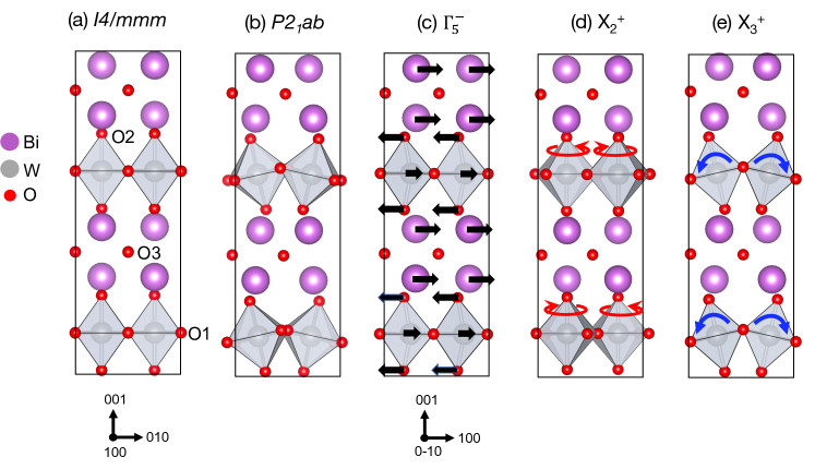
To set the stage for understanding ferroelectric switching, we first analyze the structural distortions present in the ferroelectric structure. The space group is established by the condensation of three distinct structural distortions that transform like irreducible representations (irreps) of the high-symmetry reference structure (Fig. 1a, b). These distortions are a polar displacement along the [1 0 0] orthorhombic axis which transforms like the irrep , an octahedral rotation about [0 0 1] which transforms like , and an out-of-phase ( in Glazer notation Glazer (1972)) octahedral tilt about [1 0 0] which transforms like , (Fig. 1c-e). The amplitudes of these three distortions, computed from DFT-relaxed and experimental structures, are reported in Table 1. Overall the distortion amplitudes show good agreement between DFT and experiment. The main contribution to the polar distortion comes from displacement of the Bi cations against the O2 atoms as shown in Fig. 1(c). In addition to the three distortions discussed above, there are several other distortions which are symmetry-allowed in the structure, but they have negligible amplitudes Djani et al. (2012) so we do not consider them in this work.
| Atom | ||||||||
| DFT | Expt. | DFT | Expt. | DFT | Expt. | |||
| Bi | 0.66 | 0.68 | 0 | 0 | 0.33 | 0.30 | ||
| W | 0.18 | 0.25 | 0 | 0 | 0 | 0 | ||
| O1() | 0 | 0 | 0 | 0 | 0.87 | 0.70 | ||
| O1() | -0.15 | -0.11 | 0.75 | 0.85 | 0 | 0 | ||
| O1() | -0.25 | -0.29 | -0.01 | -0.02 | 0 | 0 | ||
| O2 | -0.77 | -0.74 | 0 | 0 | -1.10 | -0.89 | ||
| O3 | 0.27 | 0.17 | 0 | 0 | -0.05 | -0.02 | ||
| Total | 1.10 | 1.09 | 0.75 | 0.85 | 1.44 | 1.17 | ||
| Irreps | Order parameter direction | Space | Amplitude (Å ) | Lattice parameters (Å ) | Energy | ||||||||
| group (No) | (meV/f.u.) | ||||||||||||
| - | - | - | - | (139) | 0 | 0 | 0 | 3.806 | 3.806 | 16.453 | 355.51 | ||
| - | (14) | 0 | 0.91 | 1.30 | 5.331 | 5.353 | 8.697 | 158.72 | |||||
| - | (61) | 0 | 0.78 | 1.35 | 5.350 | 5.360 | 16.844 | 149.74 | |||||
| - | (12) | 0 | 0.48 | 1.46 | 7.602 | 7.614 | 16.602 | 157.40 | |||||
| - | (39) | 0.44 | 0 | 1.53 | 7.601 | 7.754 | 16.481 | 103.46 | |||||
| - | (41) | 1.19 | 0 | 1.60 | 5.467 | 5.472 | 16.553 | 4.38 | |||||
| - | (36) | ||||||||||||
| - | (36) | 0.98 | 1.24 | 0 | 5.389 | 5.395 | 16.481 | 67.05 | |||||
| - | (39) | 1.01 | 1.22 | 0 | 7.601 | 7.754 | 16.481 | 71.21 | |||||
| - | (38) | 1.15 | 0.74 | 0 | 7.544 | 7.845 | 16.569 | 133.20 | |||||
| (8) | 0.45 | 0.53 | 1.46 | 7.729 | 7.584 | 16.506 | 99.06 | ||||||
| (5) | 0.49 | 0.58 | 1.45 | 7.570 | 7.740 | 16.507 | 96.68 | ||||||
| (4) | () | ||||||||||||
| (7) | 1.11 | 0.76 | 1.44 | 5.442 | 5.443 | 8.688 | -0.08 | ||||||
| (29) | 1.11 | 0.75 | 1.44 | 5.443 | 5.443 | 16.557 | 0 | ||||||
III.2 Ferroelectric switching pathways
To provide a framework for systematically identifying ferroelectric switching pathways, we next enumerate possible metastable structural phases of Bi2WO6 and compute their energies with DFT. The key to uncovering the metastable structural phases is to recognize that each of the three structural distortions shown in Figure 1 is described by a two-dimensional order parameter . Nowadnick and Fennie (2016) Here is the order parameter amplitude and is the phase. For the octahedral tilt and the polar distortion, the phase describes the orientation of the tilt (polar) axis. For the octahedral rotation, the phase describes the relative “sense” of the octahedral rotations in adjacent perovskite layers.
Each two-dimensional structural order parameter can lie along three symmetry-distinct directions (, )= (,0), (,), or (,) where are real numbers and each direction establishes a different subgroup of . For example, the space group is established by condensing the , , and distortions along the (0,), (,0) and (,) order parameter directions, respectively. Taking these order parameters to lie along different combinations of directions generates structures of different symmetries. In Table LABEL:Tab:intermediate_structures we consider all other possible combinations of the , , and order parameter directions, and enumerate the space groups that these generate (we do not include the low symmetry (,) direction in this enumeration because structures defined by this direction generally return to a higher symmetry direction upon DFT relaxation). Table LABEL:Tab:intermediate_structures also shows space groups that are generated by combining two out of the three order parameters taken along different combinations of directions. Space groups generated by each order parameter individually are given in Appendix A.
We then perform structural relaxations of Bi2WO6 with its symmetry constrained to each space group identified in Table LABEL:Tab:intermediate_structures, and report the resulting energy and structural parameters. Most metastable structures have energies ranging from 65 to 160 meV per f.u. above . We find two very low energy structures: (4.38 meV/f.u.) and which we find to be slightly lower in energy than . The and structures exhibit the same and distortions, the only difference is the relative “sense" of the rotations in adjacent perovskite layers, thus it is unsurprising that these phases are very close in energy. We note that the relative energy of and is quite sensitive to the value of the lattice parameters. For example, Ref. Djani et al., 2012 found to be about 3 meV/f.u. higher in energy than from DFT calculations with the LDA functional. Since is the experimentally reported ground state, we do not further consider the phase here.
We next use the results of Table LABEL:Tab:intermediate_structures to enumerate possible Bi2WO6 ferroelectric switching pathways. The simplest way to reverse the polarization is in a single 180∘ step, where the polarization is brought to zero and then turned on again pointing in the opposite direction, as shown in Figure 2a. At the midpoint of the path, the amplitude of the polarization is zero, and the symmetry of the crystal structure is , which is 149.74 meV/f.u. above the ground state structure (see Table LABEL:Tab:intermediate_structures). The crystal structure is shown in Figure 3a.
In addition to the one-step switching path, we identify three “two-step” switching pathways, where the polarization reverses direction by rotating through two 90 steps (while maintaining finite amplitude). Since the order parameter in is oriented along the (,) direction, rotating it by 90∘ takes it to either the (,) or (,) direction. This rotation requires that the order parameter pass through the (0,) or (,0) direction. Table LABEL:Tab:intermediate_structures reveals that the , , , and structures satisfy this requirement. Interestingly, the energies of , , and are all near 100 meV/f.u. (within 10 meV/f.u. of each other), whereas is somewhat higher (133.20 meV/f.u.). Due to its higher barrier, we do not consider the pathway further in this work.
Using these identified structures, we construct the two lowest energy two-step ferroelectric switching pathways in Figure 2(b-c). Figure 2(b) shows a pathway that passes through twice as the polarization rotates in two 90∘ steps. At the midpoint of the switching path, the structure passes through an orthorhombic twin domain of . Note that the structure passes through different domains of in the first and second steps. As the polarization rotates counterclockwise, the order parameter rotates clockwise by 90∘ in the first step, and then rotates back to its original orientation in the second step. In each step, the order parameter turns off so that it reaches zero at the structure, and then turns on again reoriented by 90∘. The structure is shown in Figure 3(b). Here the (,) direction of establishes an octahedral tilt pattern where the tilt axes of adjacent perovskite layers are perpendicular to each other, so that there are and rotations in the dark and light grey perovskite layers in Figure 3(b), respectively. Note that the higher energy pathway follows a similar evolution of structural order parameters as the path, except the rather than the order parameter rotates during the switching process.
The second two-step switching path that we investigate is shown in Figure 2(c). The and order parameters follow the same sequence as in Figure 2(b), except now the order parameter makes two 90∘ rotations while maintaining finite amplitude, rather than turning off/on. The barrier structure in the first step has symmetry , whereas in the second step it has symmetry . The and structures are shown in Figure 3(c) and (d), respectively. These structures have the same octahedral tilt pattern as . The and structures share the same rotation pattern, where every other perovskite layer (those colored green in Figure 3(c-d)) exhibit finite amplitude rotations about [0 0 1], and the other (grey) layers have no rotation amplitude. The difference between the and structures is the orientation of the polarization with respect to the and order parameters: in the polarization lies along the tilt axis of the green octahedra which have finite rotations, whereas in the polarization lies along the tilt axis of the grey octahedra which have no rotation.
In order to investigate how the energy changes during switching, Figure 2(d) shows nudged elastic band (NEB) calculations of the energy as a function of switching coordinate for the paths in Figure 2(a-c). Both two-step paths have a significantly lower energy barrier than the one-step path, with the energy barriers for the path (96.68 and 99.06 meV/f.u. in the first and second steps, taken from Table LABEL:Tab:intermediate_structures) being slightly lower than the path (103.46 meV/f.u.).
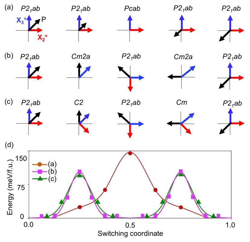
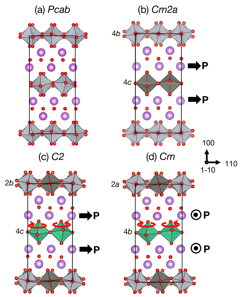
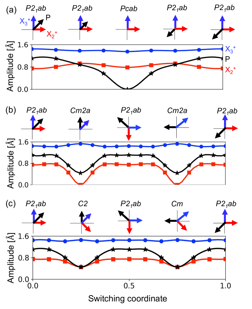
Figure 4 shows how the amplitudes of the , , and polar distortions evolve along each ferroelectric switching path, obtained from NEB calculations. In the one-step switching path shown in Figure 4(a), the polar distortion amplitude goes to zero at the barrier structure , whereas the and distortion amplitudes remain almost unchanged throughout the switching process. In the two-step switching path via shown in Figure 4(b), at the barrier the polar distortion amplitude decreases by about half and that of amplitude goes to zero, whereas the amplitude again changes very little throughout the switching process. Finally, for the two-step path shown in Figure 4(c), all three distortion amplitudes remain finite throughout the switching process, although the polar and amplitudes are suppressed upon approaching the barriers.
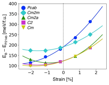
To summarize, we find that the two-step switching paths have lower energy barriers than the one-step switching path in Bi2WO6. This implies that switching proceeds via two 90∘ steps, in agreement with the experimental observations of Ref. Wang et al., 2016. We find that the two-step paths that pass through and have almost the same energy barrier (100 meV/f.u.), with the barrier for the path being slightly lower. We also investigate the epitaxial strain dependence of these energy barriers (Appendix B), and find that the two-step barriers remain the lowest energy except possibly under highly compressive strains. The two-dimensional structural order parameters facilitate the lower energy two-step switching, which involves order parameter rotation rather than completely turning the polarization off/on. We make use of these ferroelectric switching paths in the next section to guide us to the relevant structural phases in which to explore the spin orientation of magnetic dopants in Bi2WO6.
III.3 Spin directionality of magnetic dopants
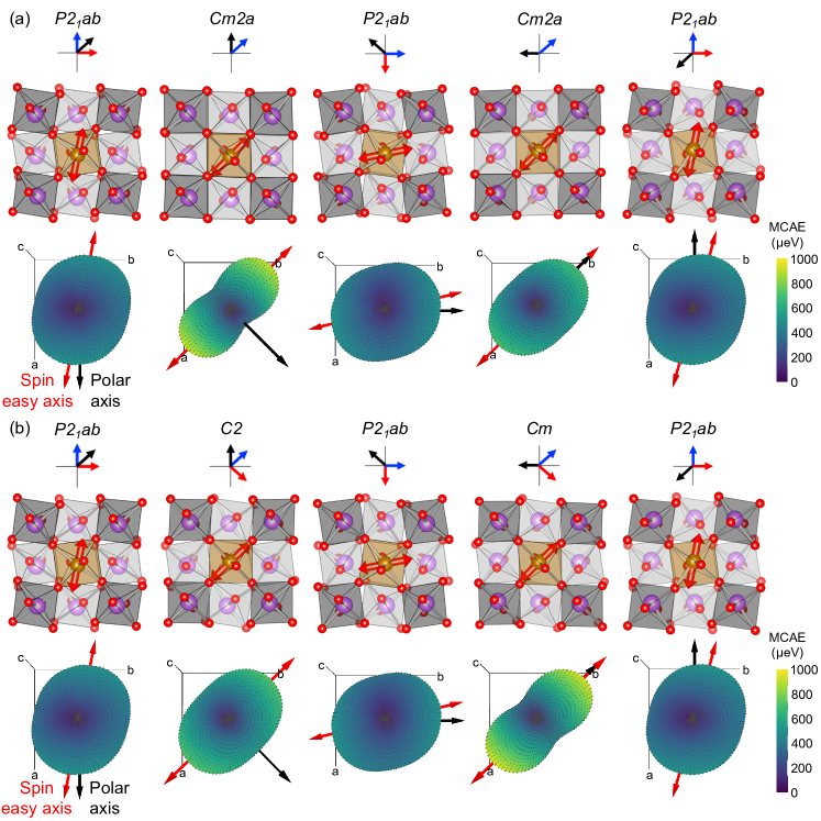
We next investigate the impact of polarization reversal on the spin orientation of magnetic dopants in Bi2WO6. Magnetic dopants in \ceBi2WO6 exhibit magnetocrystalline anisotropy – a preferred directionality of the unpaired electron spins – that arises due to the crystal field at the dopant site and spin-orbit coupling. Here, we consider Fe3+ substitutional defects on W-sites, which is one of the potential defect species in \ceBi2WO6. Although the structure only contains one distinct W site, the barrier structures encountered in the two-step switching processes contain multiple symmetry-distinct W sites (and hence dopant positions), which are shown in Figure 3(b-d). The energetics of this defect and alternative Fe-sites will be fully considered in a forthcoming work.
Figure 5 tracks the change in the MCAE surface along the two lowest energy switching pathways, and , revealing the change in directionality of the Fe-dopant spins during switching. Beginning in the phase with the polarization P oriented along [1 0 0], we identify a spin easy axis that lies in the crystallographic -plane at 11 with respect to P. In the octahedral orientation indicated in the first step, the spin easy axis is along . The calculated magnitude of the MCAE is 530 eV, which is the energy difference between the and principal axes of the MCAE surface. In addition, we calculate an in-plane anisotropy between the and principal axes of 130 eV. The principal axes of the MCAE surface for each of the switching steps are given in Appendix C.
Taking the path (Figure 5a), the Fe-dopant (along with all the octahedra in the top layer) first passes through the 4 Wyckoff position in , which has site symmetry . On this site the MCAE is significantly increased to 940 eV and the spin easy axis is . At 90 switching, the structure returns to the phase with spin easy axis now along , a rotation of 112 around the -axis from the original spin easy axis. Passing through the structure a second time, the dopant (and all octahedra in the top layer) is in the 4 Wyckoff position with site symmetry , resulting in a slightly lower MCAE of 730 eV compared to the 4 site, although the spin easy axis remains the same. This can be understood by the variation in off-centering of Fe, making a 170 O–Fe–O bond angle in the 4 position compared to 180 in the 4 position (taking the bonds aligned parallel to the spin axis). In the last step, the structure returns to with P switched by 180 and the spin easy axis returned to . (Beginning in one of the orientations in the lower layer, the Fe-dopant would pass through the 4 Wyckoff position first and the 4 position second.)
Alternatively, taking the path (Figure 5b), the Fe-dopant first passes through the phase in Wyckoff position 2 (site symmetry ) and secondly through the phase in Wyckoff position 2 (site symmetry ). The MCAE values are 750 eV and 970 eV respectively, and the spin easy axis is along in both cases. As in the path, a 90∘ switch in the polarization direction results in a rotation of the spin easy axis by 112∘ about the -axis. The similarity in crystal field environment in the two switching pathways accounts for the resemblance between the MCAE surfaces in Figure 5a-b. Details of the site symmetries and in-plane and out-of-plane MCAE are listed in Table 3, including alternative dopant positions. There are symmetrically inequivalent W-sites on the 2 Wyckoff position in and the 2 position in , which have a slightly different crystal field environment from the sites considered above, resulting in small differences in the MCAE values. In addition, an alternative domain choice for the switching pathways could have taken the Fe-dopant through the 4 position in and the 4 position in . MCAE data is not available for the latter as the structural optimization on this site did not converge the forces on the ions below a reasonable number.
The MCAEs reported here are typical of 3 transition metal atoms, Schrön et al. (2012); Rau et al. (2014) and their low magnitudes indicate that thermally induced switching could occur if not kept at very low temperatures. This could be sufficient for devices operating at cryogenic temperatures (e.g. quantum computing); an MCAE of 0.5 meV corresponds to an energy barrier of 6 K, three orders of magnitude greater than the typical mK operating temperatures of many quantum devices. However, strategies to increase the MCAE should be explored to exclude thermally induced switching in higher temperature applications. These could include systems with reduced dimensionalities and 4 or 5 transition metal and rare earth atoms which have been shown to exhibit giant MCAE values.Yu and Zang (2018); Ležaić and Spaldin (2011); Rout and Schwingenschlögl (2021); Zhou et al. (2015)
| Phase | Wyckoff | Site | MCAE (eV) | |
| site | symmetry | Out-of-plane | In-plane | |
| 4 | 1 | 530 | 130 | |
| 4 | 2 | 730 | 210 | |
| 4 | 940 | 510 | ||
| 2* | 970 | 520 | ||
| 2 | 980 | 530 | ||
| 4 | 1 | 650 | 130 | |
| 2* | 2 | 750 | 210 | |
| 2 | 2 | 760 | 200 | |
| 4 | 1 | N/A | ||
Conclusion
We use a combination of group theoretic analysis and DFT calculations to determine the intrinsic ferroelectric switching pathways of \ceBi2WO6. We identify several pathways: a one-step pathway, via , and three two-step pathways, via , and . By comparing energies of the barrier structures we find that the two-step paths are lower energy than the one-step path, in agreement with experiment: Wang et al. (2016) in particular, the path provides the lowest energy barrier of 97-99 meV/f.u. and the barrier is only slightly higher at 103 meV/f.u.. These intrinsic switching barrier energies are comparable to those of other structurally complex ferroelectrics such as LiNbO3 and Ca3Ti2O7, which have barriers of 130 meV/f.u. Ye and Vanderbilt (2016) and 64 meV/f.u. Nowadnick and Fennie (2016), respectively.
Magnetic defects experience a change in crystal field environment during switching, resulting in a change in magnetic anisotropy at each switching step. Contrasting with Fe3+ dopants in PbTiO3 which exhibit a spin easy plane Liu et al. (2021), the lower crystallographic symmetry of Bi2WO6 results in a spin easy axis. By calculating MCAE surfaces, we find how the spin orientation of a Fe3+ substitutional defect on W-sites changes during polarization switching. In the structure, the spin easy axis is in the -plane at 11 with respect to the polar axis and has an out-of-plane MCAE of 530 eV and an in-plane MCAE of 130 eV. During ferroelectric switching via intermediate phases, the spin easy axis rotates within the -plane and the MCAE is considerably increased (650-980 eV out-of-plane, 130-530 eV in-plane) due to changes in the local crystal environment of the dopant. We find that switching the polarization by 90∘ in Bi2WO6 results in a 112∘ rotation of the spin easy axis. However, a full 180∘ reversal of the polarization returns the spin easy axis to its original orientation.
Based on these results, we suggest that a possible pathway to achieve full spin control with 180∘ polarization switching is to consider ferroelectrics where an additional structural distortion that couples to the polarization must change during 180∘ switching. If this structural distortion also impacts the magnetic anisotropy, then the change to the distortion due to polarization switching may result in a different spin easy axis in the P and P states. For example, changes to octahedral rotation distortions, which are extremely common in (layered) perovskite oxides, can modify spin easy planes and axes. Liao et al. (2016); Yi et al. (2017) Although the and octahedral rotation patterns in Bi2WO6 change along the two-step switching paths, the octahedral rotation amplitudes and pattern in the starting (P) and final (P) structures are the same. However, there are other layered perovskite ferroelectrics, such as the Aurivillius compound SrBi2Ta2O9 Perez-Mato et al. (2004) and several =2 Ruddlesden-Popper ferroelectric oxides, Benedek and Fennie (2011); Nowadnick and Fennie (2016) where reversal of the polarization requires by symmetry that the sense of an octahedral rotation also reverse. Compounds such as these may provide the necessary ingredients to create distinct low symmetry environments and hence different MCAE surfaces in polarization reversed states.
Acknowledgements
This work was supported by the Microelectronics Co-Design Research Program, under the Office of Science of the U.S. Department of Energy under Contract No. DE-AC02-05CH11231 (K.I., N.L., and S.M.G.). N.P., Z.C., S.P.R., and E.A.N. acknowledge support from University of California, Merced. Computational resources were provided by the National Energy Research Scientific Computing Center and the Molecular Foundry, DOE Office of Science User Facilities supported by the Office of Science, U.S. Department of Energy under Contract No. DE-AC02-05CH11231. The work performed at the Molecular Foundry was supported by the Office of Science, Office of Basic Energy Sciences, of the U.S. Department of Energy under the same contract. We also acknowledge the use of computational resources supported by the Center for Functional Nanomaterials, which is a U.S. DOE Office of Science Facility, and the Scientific Data and Computing Center, a component of the Computational Science Initiative, at Brookhaven National Laboratory under Contract No. DE-SC0012704. In addition, this work used the Extreme Science and Engineering Discovery Environment (XSEDE) Expanse cluster at the San Diego Supercomputing Center through allocation TG-PHY200085.
Author contributions
K.I. and N.P. contributed equally to this work.
Appendix A Additional subgroups of
Table A1 reports the subgroups of generated by distinct directions of the , , and order parameters, along with the distortion amplitudes, lattice parameters, and total energies of Bi2WO6 after DFT structural relaxations in each space group.
| Irrep | Direction | Space group (No) | Amplitude (Å) | Lattice parameters (Å ) | Energy (meV/f.u.) | ||
| (44) | 1.47 | 5.472 | 5.472 | 16.575 | 154.54 | ||
| (42) | 1.25 | 5.504 | 5.461 | 16.436 | 133.91 | ||
| (64) | 1.31 | 5.290 | 5.290 | 16.646 | 231.32 | ||
| (127) | 0.80 | 5.349 | 5.349 | 16.524 | 310.16 | ||
| (64) | 1.48 | 5.368 | 5.395 | 16.663 | 178.40 | ||
| (138) | 1.51 | 5.393 | 5.393 | 16.576 | 161.40 | ||
Appendix B Epitaxial strain
Figure A1 presents the energies of the ferroelectric switching barrier structures discussed in the main text as a function of epitaxial strain. In these calculations, biaxial strain is applied in the -plane, and the lattice parameter and all atomic positions are allowed to relax. We find that all energy barriers increase upon going from compressive to tensile strain. The energy barrier changes the most dramatically with strain. The structures provide the lowest energy barriers at all strains that we consider, although under highly compressive strains (larger than 2) the barrier may become lowest, which would suggest a crossover from two- to one-step switching being the lowest energy path.
Appendix C Principal axes of magnetocrystalline anisotropy energy surfaces
Table A2 reports the principal axes of the MCAE surfaces shown in Figure 5. These axes are orthonormal vectors which describe the three principal axes of rotation of the MCAE surface. The spin easy axis lies along the principal axis.
| Switching | Phase | Wyckoff | Principal axes | ||
| figure | site | ||||
| 5(a) | 4 | [1.0 -0.2 0.0] | [0.2 0.9 0.3] | [-0.1 -0.3 0.9] | |
| 4 | [0.7 -0.7 0.0] | [0.6 0.6 -0.5] | [-0.3 -0.3 -0.9] | ||
| 4 | [-0.2 1.0 0.0] | [-0.9 -0.2 -0.3] | [-0.3 -0.1 0.9] | ||
| 4 | [0.7 -0.7 0.0] | [-0.7 -0.7 -0.3] | [0.2 0.2 -0.9] | ||
| 4 | [-1.0 0.2 0.0] | [0.2 0.9 0.3] | [0.1 0.3 -0.9] | ||
| 5(b) | 4 | [1.0 -0.2 0.0] | [0.2 0.9 0.3] | [-0.1 -0.3 0.9] | |
| 2 | [0.7 -0.7 0.0] | [-0.7 -0.7 -0.3] | [0.2 0.2 -1.0] | ||
| 4 | [-0.2 1.0 0.0] | [-0.9 -0.2 -0.3] | [-0.3 -0.1 0.9] | ||
| 2 | [-0.7 0.7 0.0] | [-0.6 -0.6 -0.4] | [-0.3 -0.3 0.9] | ||
| 4 | [-1.0 0.2 0.0] | [0.2 0.9 0.3] | [0.1 0.3 -0.9] | ||
References
- Spaldin and Ramesh (2019) N. A. Spaldin and R. Ramesh, Nat. Mater. 18, 203 (2019).
- Manipatruni et al. (2019) S. Manipatruni, D. E. Nikonov, C. C. Lin, T. A. Gosavi, H. Liu, B. Prasad, Y. L. Huang, E. Bonturim, R. Ramesh, and I. A. Young, Nature 565, 35 (2019).
- Mundy et al. (2016) J. A. Mundy, C. M. Brooks, M. E. Holtz, J. A. Moyer, H. Das, A. F. Rébola, J. T. Heron, J. D. Clarkson, S. M. Disseler, Z. Liu, A. Farhan, R. Held, R. Hovden, E. Padgett, Q. Mao, H. Paik, R. Misra, L. F. Kourkoutis, E. Arenholz, A. Scholl, J. A. Borchers, W. D. Ratcliff, R. Ramesh, C. J. Fennie, P. Schiffer, D. A. Muller, and D. G. Schlom, Nature 537, 523 (2016).
- Cai et al. (2017) R. Cai, V.-A. Antohe, Z. Hu, B. Nysten, L. Piraux, and A. M. Jonas, Adv. Mater. 29, 1604604 (2017).
- Catalan et al. (2012) G. Catalan, J. Seidel, R. Ramesh, and J. F. Scott, Rev. Mod. Phys. 84, 119 (2012).
- Wang et al. (2003) J. Wang, J. B. Neaton, H. Zheng, V. Nagarajan, S. B. Ogale, B. Liu, D. Viehland, V. Vaithyanathan, D. G. Schlom, U. V. Waghmare, N. A. Spaldin, K. M. Rabe, M. Wuttig, and R. Ramesh, Science 299, 1719 (2003).
- Boudalis et al. (2018) A. K. Boudalis, J. Robert, and P. Turek, Chem. Eur. J. 24, 14896 (2018).
- Liu et al. (2019) J. Liu, J. Mrozek, W. K. Myers, G. A. Timco, R. E. Winpenny, B. Kintzel, W. Plass, and A. Ardavan, Phys. Rev. Lett. 122, 037202 (2019).
- Fittipaldi et al. (2019) M. Fittipaldi, A. Cini, G. Annino, A. Vindigni, A. Caneschi, and R. Sessoli, Nat. Mater. 18, 329 (2019).
- Liu et al. (2021) J. Liu, V. V. Laguta, K. Inzani, W. Huang, S. Das, R. Chatterjee, E. Sheridan, S. M. Griffin, A. Ardavan, and R. Ramesh, Sci. Adv. 7, eabf8103 (2021).
- Johnson et al. (2019) A. I. Johnson, F. Islam, C. M. Canali, and M. R. Pederson, J. Chem. Phys. 151, 4 (2019).
- Utkin et al. (1980) V. I. Utkin, Y. E. Roginskaya, V. I. Voronkova, V. K. Yanovskii, B. Sh. Galyamov, and Y. N. Venevtsev, Phys. Stat. Sol. (a) 59, 75 (1980).
- Jardiel et al. (2008) T. Jardiel, A. C. Caballero, and M. Villegas, J. Ceram. Soc. Japan 116, 511 (2008).
- Campanini et al. (2019) M. Campanini, M. Trassin, C. Ederer, R. Erni, and M. D. Rossell, ACS Appl. Elect. Mater. 1, 1019 (2019).
- De Araujo et al. (1995) C.-P. De Araujo, J. Cuchiaro, L. McMillan, M. Scott, and J. Scott, Nature 374, 627 (1995).
- Mao et al. (2009) X. Mao, W. Wang, X. Chen, and Y. Lu, Appl. Phys. Lett. 95, 1 (2009).
- Keeney et al. (2013) L. Keeney, T. Maity, M. Schmidt, A. Amann, N. Deepak, N. Petkov, S. Roy, M. E. Pemble, and R. W. Whatmore, J. Am. Ceram. Soc. 96, 2339 (2013).
- Chen et al. (2014) X. Chen, J. Xiao, Y. Xue, X. Zeng, F. Yang, and P. Su, Cera. Int. 40, 2635 (2014).
- Wang et al. (2015) J. Wang, Z. Fu, R. Peng, M. Liu, S. Sun, H. Huang, L. Li, R. J. Knize, and Y. Lu, Mater. Horiz. 2, 232 (2015).
- Li et al. (2016) Z. Li, J. Ma, Z. Gao, G. Viola, V. Koval, A. Mahajan, X. Li, C. Jia, C. Nan, and H. Yan, Dalton Trans. 45, 14049 (2016).
- Keeney et al. (2012) L. Keeney, S. Kulkarni, N. Deepak, M. Schmidt, N. Petkov, P. F. Zhang, S. Cavill, S. Roy, M. E. Pemble, and R. W. Whatmore, J. Appl. Phys. 112, 0 (2012).
- Moore et al. (2021) K. Moore, E. O’Connell, S. M. Griffin, L. Keeney, C. Downing, M. Schmidt, V. Nicolosi, U. Bangert, and M. Conroy, Research Square (2021).
- Birenbaum and Ederer (2014) A. Y. Birenbaum and C. Ederer, Phys. Rev. B 90, 214109 (2014).
- Zhai et al. (2018) X. Zhai, A. J. Grutter, Y. Yun, Z. Cui, and Y. Lu, Phys. Rev. Materials 2, 044405 (2018).
- Faraz et al. (2017) A. Faraz, T. Maity, M. Schmidt, N. Deepak, S. Roy, M. E. Pemble, R. W. Whatmore, and L. Keeney, J. Amer. Ceram. Soc. 100, 975 (2017).
- Machado et al. (2004) R. Machado, M. G. Stachiotti, R. L. Migoni, and A. Huanosta Tera, Phys. Rev. B 70, 214112 (2004).
- Mohn and Stølen (2011) C. E. Mohn and S. Stølen, Phys. Rev. B 83, 014103 (2011).
- Djani et al. (2012) H. Djani, E. Bousquet, A. Kellou, and P. Ghosez, Phys. Rev. B 86, 054107 (2012).
- Wang et al. (2016) C. Wang, X. Ke, J. J. J. Wang, R. Liang, Z. Luo, Y. Tian, D. Yi, Q. Zhang, J. J. J. Wang, X. F. Han, G. Van Tendeloo, L. Q. Chen, C. W. Nan, R. Ramesh, and J. Zhang, Nat. Comm. 7, 1 (2016).
- Okudera et al. (2018) H. Okudera, Y. Sakai, K. Yamagata, and H. Takeda, Acta Crystallogr. Sec. B 74, 295 (2018).
- McDowell et al. (2006) N. A. McDowell, K. S. Knight, and P. Lightfoot, Chem. Eur. J. 12, 1493 (2006).
- Beckman et al. (2009) S. P. Beckman, X. Wang, K. M. Rabe, and D. Vanderbilt, Phys. Rev. B 79, 144124 (2009).
- Heron et al. (2014) J. Heron, J. Bosse, Q. He, Y. Gao, M. Trassin, L. Ye, J. Clarkson, C. Wang, J. Liu, S. Salahuddin, et al., Nature 516, 370 (2014).
- Nowadnick and Fennie (2016) E. A. Nowadnick and C. J. Fennie, Phys. Rev. B 94, 104105 (2016).
- Kresse and Hafner (1993) G. Kresse and J. Hafner, Phys. Rev. B 47, 558 (1993).
- Kresse and Hafner (1994) G. Kresse and J. Hafner, Phys. Rev. B 49, 14251 (1994).
- Kresse and Furthmüller (1996a) G. Kresse and J. Furthmüller, Comp. Mater. Sci. 6, 15 (1996a).
- Kresse and Furthmüller (1996b) G. Kresse and J. Furthmüller, Phys. Rev. B 54, 11169 (1996b).
- Blöchl (1994) P. E. Blöchl, Phys. Rev. B 50, 17953 (1994).
- Kresse and Joubert (1999) G. Kresse and D. Joubert, Phys. Rev. B 59, 1758 (1999).
- Perdew et al. (2008) J. P. Perdew, A. Ruzsinszky, G. I. Csonka, O. A. Vydrov, G. E. Scuseria, L. A. Constantin, X. Zhou, and K. Burke, Phys. Rev. Lett. 100, 136406 (2008).
- Henkelman et al. (2000) G. Henkelman, B. P. Uberuaga, and H. Jónsson, J. Chem. Phys. 113, 9901 (2000).
- Dudarev et al. (1998) S. L. Dudarev, G. A. Botton, S. Y. Savrasov, C. J. Humphreys, and A. P. Sutton, Phys. Rev. B 57, 1505 (1998).
- (44) H. Stokes, D. Hatch, and B. Campbell. ISOTROPY software suite, http://stokes.byu.edu/isotropy.html.
- Momma and Izumi (2008) K. Momma and F. Izumi, J. Appl. Crystallogr. 41, 653 (2008).
- Glazer (1972) A. Glazer, Acta Crystallogr. Sec. B 28, 3384 (1972).
- Rae et al. (1991) A. D. Rae, J. G. Thompson, and R. L. Withers, Acta Crystallogr. Sec. B 47, 870 (1991).
- Schrön et al. (2012) A. Schrön, C. Rödl, and F. Bechstedt, Phys. Rev. B 86, 115134 (2012).
- Rau et al. (2014) I. G. Rau, S. Baumann, S. Rusponi, F. Donati, S. Stepanow, L. Gragnaniello, J. Dreiser, C. Piamonteze, F. Nolting, S. Gangopadhyay, et al., Science 344, 988 (2014).
- Yu and Zang (2018) J.-X. Yu and J. Zang, Sci. Adv. 4, eaar7814 (2018).
- Ležaić and Spaldin (2011) M. Ležaić and N. A. Spaldin, Phys. Rev. B 83, 024410 (2011).
- Rout and Schwingenschlögl (2021) P. C. Rout and U. Schwingenschlögl, Nano Lett. 21, 6807 (2021).
- Zhou et al. (2015) J. Zhou, Q. Wang, Q. Sun, Y. Kawazoe, and P. Jena, Physical Chemistry Chemical Physics 17, 17182 (2015).
- Ye and Vanderbilt (2016) M. Ye and D. Vanderbilt, Phys. Rev. B 93, 134303 (2016).
- Liao et al. (2016) Z. Liao, M. Huijben, Z. Zhong, N. Gauquelin, S. Macke, R. Green, S. Van Aert, J. Verbeeck, G. Van Tendeloo, K. Held, et al., Nat. Mater. 15, 425 (2016).
- Yi et al. (2017) D. Yi, C. L. Flint, P. P. Balakrishnan, K. Mahalingam, B. Urwin, A. Vailionis, P. Shafer, E. Arenholz, Y. Choi, K. H. Stone, et al., Phys. Rev. Lett. 119, 077201 (2017).
- Perez-Mato et al. (2004) J. Perez-Mato, M. Aroyo, A. García, P. Blaha, K. Schwarz, J. Schweifer, and K. Parlinski, Phys. Rev. B 70, 214111 (2004).
- Benedek and Fennie (2011) N. A. Benedek and C. J. Fennie, Phys. Rev. Lett. 106, 107204 (2011).