MARISA: A Self-configuring Metasurfaces Absorption and Reflection Solution Towards 6G
Abstract
Reconfigurable Intelligent Surfaces (RISs) are considered one of the key disruptive technologies towards future 6G networks. RISs revolutionize the traditional wireless communication paradigm by controlling the wave propagation properties of the impinging signals at will. A major roadblock for RIS is though the need for a fast and complex control channel to continuously adapt to the ever-changing wireless channel conditions. In this paper, we ask ourselves the question: Would it be feasible to remove the need for control channels for RISs? We analyze the feasibility of devising Self-Configuring Smart Surfaces that can be easily and seamlessly installed throughout the environment, following the new Internet-of-Surfaces (IoS) paradigm, without requiring modifications of the deployed mobile network. To this aim we design MARISA, a self-configuring metasurfaces absorption and reflection solution. Our results show that MARISA achieves outstanding performance, rivaling with state-of-the-art control channel-driven RISs solutions.
Index Terms:
5G, 6G, RIS, Self-configuring, HRIS, IRS, IoSI Introduction
††This work has been supported by EU H2020 RISE-6G project under grant agreement no. 101017011.The impelling need for unprecedented network performance has indicted the classical communication paradigm for not being able to fully control the propagation environment towards astounding wireless transmission efficiency targets. This has called for a revolutionary technology that could provide the means for continuously monitoring the surrounding environment and selfishly control how signal waves propagate [1]: Metasurfaces with their reflectarray-based variant, namely Reconfigurable Intelligent Surface (RIS), epitomize a fully controllable and flexible smart propagation environment built on top of man-made surfaces that alter the radio propagation properties of the impinging signals in favor of specific directions. While this game-changing technology introduces a bulk of new business opportunities and advanced use-cases for the next generation of wireless networks (B5G or 6G), it involves technical challenges that are not easy to address[2].
The RIS paradigm turns weaknesses into strengths: the imagery of a black-box environment is transformed into a smart place packed with a massive number of surfaces that are equipped with low-cost and low-complexity electronics [3]. However, an ad-hoc control channel is essential to dynamically reconfigure the propagation of radio waves based on current network dynamics. Additionally, due to the absence of signal processing units on such nearly-passive surfaces, channel estimation and acquisition are usually performed over the entire transmitter-RIS-receiver path, which may prevent the agile deployment of the surfaces[4].
The expected high market penetration of such devices cannot impose, however, stringent requirements on their agile deployment and configuration, as these are essential features for the openness of radio access networks[5], which would put into question how easily the RIS technology will be seamlessly integrated into existing networks and standards [6]. Therefore, in this paper, we take the Internet-of-Things (IoT) to the next level, by coining and introducing the Internet-of-Surfaces (IoS) paradigm: a multitude of simple reconfigurable devices that can be seamlessly plugged into the existing network infrastructure without requiring sophisticated installation procedures and that can autonomously play to enhance communications key performance indicators (KPIs).
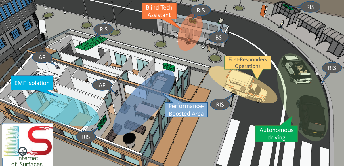
In Fig. 1, the IoS reference scenario is depicted, wherein RISs are densely deployed and strategically placed to extend existing customer services or to enable new ones. Indoor applications may include areas where coverage and connectivity are boosted (performance-boosted areas), as well as specific locations where the electromagnetic field (EMF) exposure can be effectively reduced (EMF isolation) [7]. Interestingly, autonomous driving, e-accessibility, and first-responders operations may be supported by RIS-empowered networks without requiring the installation and maintenance of additional access points (APs) or base stations (BSs) [8].
Building upon the envisioned IoS paradigm, this paper presents a novel solution, namely Metasurface Absorption and Reflection for Intelligent Surface Applications (MARISA), which leverages Hybrid Reconfigurable Intelligent Surfaces (HRISs), described in Section II, as plug-and-play devices with reflection and power-sensing capabilities. MARISA is built upon ) a new channel estimation model lato-sensu at the RIS, which is introduced in Section III and ) an autonomous RIS configuration methodology based only on the channel state information (CSI) of the BS-RIS and user equipment (UE)-RIS paths without involving an active control channel, which is described in Section IV. Finally, in Section V, MARISA is shown to provide near-optimal performance when compared to the full-CSI-aware approach.
Notation. We denote matrices and vectors in bold text while each of their element is indicated in roman with a subscript. and stand for vector or matrix transposition and Hermitian transposition, respectively. The L-norm of a vector and the Frobenius norm of a matrix are denoted as and , respectively, and indicates the trace of a square matrix. Also, denotes the inner product between vectors, and denotes the Hadamard product between two matrices.
II Plug & Play HRIS: Key Characteristics
In this section, we introduce the key concept of HRIS and provide a brief overview of the proposed bespoke hardware design. Then, we analyze the challenges that need to be overcome to enable self-configuration capabilities for the IoS.
II-A Preliminaries
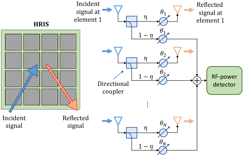
We consider an HRIS [9] comprising an array of hybrid meta-atoms, which are able to simultaneously reflect and absorb (i.e., sense the power of) incident signals. In the considered architecture, each metasurface element is coupled with a sampling waveguide that propagates the absorbed (i.e., sensed) power of the incident electromagnetic (EM) waves towards some downstream radio frequency (RF) hardware for enabling signal processing.
To reduce the complexity and cost of the required hardware, the proposed plug-and-play (P&P) HRISs are not equipped with fully-fledged RF chains but only with an RF power detector, thereby eliminating the need for a receiver. As shown in Fig. 2, the signals sensed by each metasurface element are summed together by some RF combiners, which may be easily implemented as lumped components throughout the metasurface RF circuit [10]. The resulting signal is fed into an RF power detector that converts the RF power into a measurable direct current (DC) or a low frequency (LF) signal, which is, e.g., made of a thermistor or a diode detector, [11, 12]. In the considered hardware architecture, the reflected and absorbed signals are subject to the same phase shifts applied by the metasurface elements, which are tuned to simultaneously control the signal reflection and power absorption properties of the HRIS. Nonetheless, it is possible to enable the fully-absorption operating mode by deactivating the reflection of signals by means of simple varactor diodes [13].
II-B The Road Towards the IoS: Self-Configuring RISs
Managed RIS deployment. Conventional state-of-the-art (SoA) RIS deployments rely on a control channel between the RISs and a centralized controller111Current RISs are conventionally controlled by a centralized entity (i.e., an orchestration layer) or by the BS itself. Within the O-RAN-compliant architecture, this might be achieved through an ad-hoc interface that is placed between the Near-Real Time (RT) RAN Intelligent Controller (RIC) and the RIS controller, which, however, leads to additional overhead., which serves a twofold purpose: ) sharing the CSI estimated at the BS and the RISs, ) enabling the joint optimization of the BS precoding matrix and the phase shifts at the RIS elements, in order to avoid losses due to the out-of-phase reception of uplink signals at the BS or downlink signals at the user equipments (UEs). Indeed, if both the direct and reflected (through one or multiple RISs) propagation links between the BS and a UE are available, the transmission delays experienced by the transmit signals over the two paths may be substantially different, thereby requiring the RIS to be configured for compensating them. Such configuration is feasible only if the centralized control entity has perfect CSI of the direct and reflected propagation channels, as well as it has full control on the RIS configuration.
Unmanaged HRIS deployment. Avoiding the need for an external management and control entity has major positive implications for the design and deployment of RIS-aided wireless networks. In the IoS landscape showcased in Fig. 1, in fact, we envision that novel devices like the HRISs will be completely autonomous and self-configuring without requiring an external control channel, thereby maximizing the agility and flexibility of their deployment while keeping the installation, configuration and maintenance costs affordable. As currently available implementations of RISs cannot operate without an external control channel, we leverage on the concept of HRIS to propose the first-of-its-kind solution that does not rely on the existence of a remote control channel but is built upon the optimization and configuration of the HRIS uniquely based on local estimates of the CSI at the HRIS itself.
Power-based indirect beamforming. As shown in Fig. 2, the proposed HRIS design includes only one RF power detector, which can only measure the power of all the incident signals at every HRIS meta-atom. Most available angle of arrival (AoA) estimation techniques necessitate the signal samples at each receive antenna. Conversely, we make the most out of our proposed hardware design and perform an indirect estimation of the AoA, by optimizing the phase shifts applied to the absorbed (sensed) signals at every meta-atom so as to maximize the power sensed by the detector. As adjusting the phase shifts applied by the meta-atoms is equivalent to realizing a virtual (passive) beamformer towards specified AoA of the incident signals with respect to the HRIS surface, we can take advantage of the power sensing capability of the HRISs for estimating the BS-HRIS and HRIS-UE channels with very little local information.
HRIS self-configuration. The optimal configuration of the HRISs is discussed in Section III-B. Here, we anticipate that any algorithmic solutions for optimizing the HRIS require the estimation of the CSI of the BS-HRIS and HRIS-UE channels. This results in a chicken-egg problem that needs to be tackled. To this end, we devise an online optimization approach that relies upon a finite set of HRIS configurations, namely a codebook, that can be iteratively tested for probing a finite set of predefined AoAs. It is worth mentioning that this operation may have a disruptive impact on the network operation: a given HRIS configuration may be in use for assisting, through smart reflections, the data transmission of some BSs and UEs. Therefore, changing the HRIS configuration for sensing may negatively affect the communication performance. MARISA addresses this issue by means of a simultaneous hybrid probing and communication scheme, as detailed in Section IV-A.
III Model Design
In this section, we introduce the reference analytical model for the considered wireless HRIS-aided network scenario. We start by stating the HRIS configuration problem accounting for the practical limitations of such hardware platform.
III-A System Model
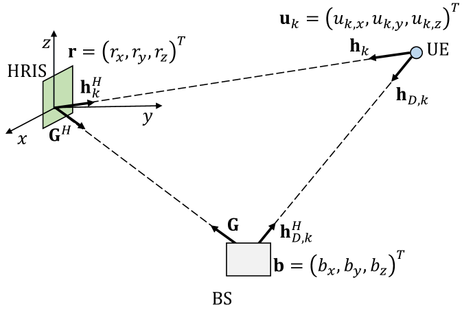
We consider the scenario depicted in Fig. 3, in which a BS equipped with antennas serves single-antenna UEs with the aid of an HRIS. We model the BS as a uniform linear array (ULA), and the HRIS as a planar linear array (PLA) equipped with meta-atoms, where and denote the number of elements along the and axis, respectively. We assume that the inter-distance of the BS and HRIS array elements is , where denotes the carrier wavelength, is the corresponding carrier frequency and is the speed of light. The joint reflection and absorption capabilities of the HRIS are realized through directional couplers whose operation is determined by the parameter , which is the fraction of the received power that is reflected for communication, while is the amount of absorbed power. A practical implementation of this architecture can be found in [9].
We denote by , and the locations of the BS center, the HRIS center and the -th UE, respectively. Focusing on the downlink, the BS transmits data to the -th UE over a direct line-of-sight (LoS) link and a reflected link through the HRIS. Such path can be decomposed into the LoS channel through which the HRIS reflects the impinging signal towards the UE, and the LoS channel between the BS and the HRIS. The array response vector at the BS towards the location is denoted by whose elements are defined as
| (1) |
where is the wave vector, defined as
| (2) |
with denoting the coordinates of the -th BS antenna element.
Likewise, the HRIS array response vector towards the location is denoted by whose elements are
| (3) |
where is the corresponding wave vector
| (4) |
and is the coordinate of the -th meta-atom of the HRIS.
The overall gain of a generic communication path between two given locations , is defined as
| (5) |
where is the channel power gain at a reference distance and is the pathloss exponent. Hence, we can write the BS-HRIS and the HRIS- channels as
| (6) | ||||
| (7) |
while the direct BS- channel is
| (8) |
Thus, the received signal at the -th UE is
| (9) |
where , with and , being the phase shifts and the gains introduced by the HRIS, is the transmit precoding matrix whose -th column is the transmit precoder of , is the transmit symbol vector with , and is the noise term whose distribution is . For tractability, we assume that the same HRIS configuration (i.e., the phase shifts in Fig. 2) is applied to the incident signals to compute the absorbed and reflected power. Although the two branches of the directional couplers in Fig. 2 may have dedicated phase shifters, we assume that they are the same. This assumption allows us to find a simple and useful relationship between the optimal phase shift configuration for both the reflection and absorption functions, which is beneficial for optimizing the HRIS. Moreover, we assume that and can be independently optimized.
III-B HRIS Optimization
In this section, we focus our attention on how an HRIS can be endowed with self-configuring capabilities, and, in particular, how the absence of a dedicated control channel results in the need for the HRIS of locally estimating the channels towards the BS and the UE, in order to establish and maintain a high-quality reflected path. To this end, we commence by formulating the optimization problem without imposing the absence of the control channel, and we then elaborate on the difficulty of solving the obtained problem by relying only on local CSI at the RIS.

The signal-to-interference-plus-noise ratio (SINR) at the -th UE can be written as
| (10) |
where is assumed to be given during the optimization of the configuration of the HRIS. More precisely, is optimized by the BS after the channel estimation phase. The disjoint optimization of and the RIS configuration facilitates the design and deployment of a control channel-free HRIS, which is the focus of this paper. The optimization of is elaborated in further text. We aim at finding the optimal HRIS configuration that maximizes the network sum-rate, which is directly related to the SINR at every UE, as exemplified in the toy scenario of Fig. 4. More precisely, the network sum-rate is defined as
| (11) |
which results in the following optimization problem.
Problem 1 (SINR-based HRIS configuration)
| s.t. |
Problem 1 is a fractional program (FP), since it falls into the family of optimization problems involving at least one ratio of two functions. To tackle it, we apply the FP Quadratic Transform method [14] to the objective function in (11), and obtain the following equivalent optimization problem.
Problem 2 (SINR-based HRIS configuration reformulated)
| s.t. | |||
where
| (12) |
| (13) |
Problem 2 has the notable property of being convex in the variables and separately. Therefore, it can be efficiently (but sub-optimally) tackled by alternating the optimization over and over the auxiliary variables . However, it cannot be locally solved at the HRIS for three reasons: i) the lack of digital signal processing units at the surface, ii) the capability of the HRIS to execute only power measurements, and, more importantly, iii) because Problem 2 requires the CSI of the direct link between the BS and each UE, which can be obtained only through a control and feedback channel.
These considerations call for an alternative approach that takes into account the constraints on the design and deployment of HRISs, while taking advantage of the massive availability of HRISs in IoS-based networks. A solution that fulfills these requirements can be obtained by direct inspection of the SINR in (10), and by taking into account the limitations of the HRIS in terms of RF and signal processing hardware, as well as the absence of a control channel.
A feasible strategy to optimize the SINR for every UE is to optimize the HRIS configuration so that the intensity of is maximized, i.e., the end-to-end RIS-assisted channel gain of each user is enhanced. This approach is approximately equivalent to maximizing the while ignoring the interfering term in (13). Upon completion of this optimization, the BS can optimize the precoding matrix , in order to co-phase the direct and the path reflected through the HRIS. Indeed, even though the BS cannot control the HRIS configuration due to the absence of a control channel, it can always estimate the direct channel towards each UE and the equivalent RIS-assisted link.
Channel estimation and HRIS configuration. Let us now focus our attention on the optimization of the HRIS configuration, by taking into account that it is equipped with a single RF power detector. To this end, we commence by deriving a closed-form expression for the HRIS configuration that maximizes the reflected power. We assume that a training phase exists, during which the BS and each UE transmit a pilot symbol in order to realize the initial beam alignment procedure222This standard procedure is essential before data transmission in, e.g., millimeter-wave networks for initial device discovery and channel estimation [15].. Without loss of generality, we assume a certain degree of synchronization, i.e., the BS and the UEs transmit at different times, but all UEs transmit simultaneously. We will relax this latter assumption in Section IV-A.
For ease of presentation, we define the vector
| (14) |
such that . The signals at the output of the RF combiner, which are obtained from the pilot signals transmitted by the BS and the UEs, can be formulated as
| (15) | ||||
| (16) |
where we assume that the BS and the UEs emit the same amount of power and is the additive noise term. Let be the optimal BS precoder for the BS-HRIS link. We will see shortly that the knowledge of is not explicitly needed to optimize the HRIS configuration. Also, we define . Since the UE-HRIS channel corresponds to the uplink, to use it in the downlink, we assume that the channel reciprocity holds.
Therefore, the detected power and from the pilot signals emitted by the BS and the UEs, respectively, can be formulated as
| (17) | ||||
| (18) |
In order to be self-configuring, an HRIS needs to infer the channels and only based on and in (17) and (18), respectively. This is equivalent to finding the configuration of the HRIS that maximizes and , which in turn corresponds to estimating the directions of incidence of the signals on the HRIS. As a result, we formulate the following optimization problem, whose solution is the HRIS configuration that maximizes
| (19) | ||||
| s.t. |
where is the th element of .
The objective function in (19) can be recast as
| (20) |
where is the projection of the BS precoding vector onto the BS-HRIS direction.
Hence, the optimal HRIS configuration for maximizing the absorbed power from the BS is with
| (21) |
Analogously, the optimal HRIS configuration that maximizes is with
| (22) |
From (21) and (22), we evince, as anticipated, that the optimal HRIS configuration that maximizes the sensed power depends only on the HRIS array response vectors towards the BS and UE directions, but it is independent of the (optimal) BS precoding vector.
Based on and , we are now in the position of proposing a distributed approach for optimizing the HRIS. In particular, we formulate the following optimization problem.
Problem 3 (Multi-UE SINR-based HRIS configuration)
| (23) | ||||
| s.t. |
Problem 3 is independent of the direct channels between the BS and the UEs, as well as of the BS precoder : these are fundamental requirements due to the lack of control channel. With the aid of Cauchy–Schwarz’s inequality, we obtain
| (24) |
implying that the objective function in (23) is a lower bound for the sum of the powers of the signals transmitted by the UEs independently, which are sensed by the HRIS. Notably, the inequality in (24) becomes an equality if and only if the channels are orthogonal to each other.
By using (24), the objective function in (23) can be reformulated as
| (25) |
where is the equivalent channel that accounts for the overall effect of the aggregate UE-HRIS channels from the HRIS standpoint, and is the reflected path between the BS and the HRIS for a given precoder at the BS.
Therefore, the HRIS optimal configuration solution of Problem 3 is
| (26) |
which proves that the HRIS configuration in the absence of a control channel can be inferred solely from and .
Single-UE scenario. In the single-UE scenario, some interesting conclusions can be drawn. In this case, the signal-to-noise ratio (SNR) can be written as
| (27) |
where we have omitted the UE index for simplicity. Similar to (25), the numerator in (27) can be reformulated as
| (28) |
with and . With the aid of some algebraic manipulations, (28) simplifies to
| (29) |
which elucidates that the optimal HRIS configuration needs to fulfill two conditions: ) the maximization of the reflected path gain and ) the phase alignment between the direct and reflected paths, i.e., and .
Finally, we note that in (26) is optimal only in the absence of the LoS path, , between the BS and the UE. When the BS-UE link is not negligible, the optimality of is guaranteed if and only if the direct and reflect paths are aligned in phase.
IV Codebook-Based Optimization of HRISs
Problem 3 provides us with a mathematical model for optimizing the HRIS configuration. From a practical standpoint, however, the optimal solution in (26) depends on the array response vectors from the HRIS towards the BS and the UEs. To implement the obtained solution, the array response vectors, i.e., the BS-RIS and RIS-UEs AoAs, need to be estimated, but this is not possible at the HRIS due to the absence of RF chains and of a control channel. In this section, we propose a codebook-based approach for estimating the necessary AoAs and then computing in a distributed manner and locally at the HRIS, i.e., our proposed MARISA.
IV-A MARISA
MARISA optimizes the HRISs based on an appropriately designed codebook (see Section IV-B), which allows for the estimation of the BS-RIS and RIS-UEs AoAs in a distributed manner. The use of codebooks is a known approach in RIS-assisted communications, e.g., [16, 17], and it is usually implemented by assuming that the electronic circuits of the RIS can realize a finite number of phase responses (e.g., through PIN diodes [18]). Therefore, our proposed MARISA is compatible with conventional implementations of RISs, but it does not need a control channel.
Let us consider a codebook , whose codewords are unit-norm beamforming vectors that correspond to a discrete set of possible phase shift matrices . In particular, each codeword is constituted by discrete-valued entries that mimic a sort of phase quantization. The discrete values of the codewords are assumed to belong to the following set
| (30) |
where is the possible number of discrete values.
In MARISA, the HRIS operates in two possible modes: probing and communication. In the probing mode, the HRIS estimates the AoAs that correspond to the BS and to the UEs. In the communication mode, the HRIS assists the transmission of data between the BS and the UEs, while still being capable of detecting new UEs joining the network or previously inactive UEs. Therefore, we relax the assumption of simultaneous UEs transmissions introduced in Section III-B, i.e., the UEs may transmit at different times. Probing and communication phases are detailed in the following.
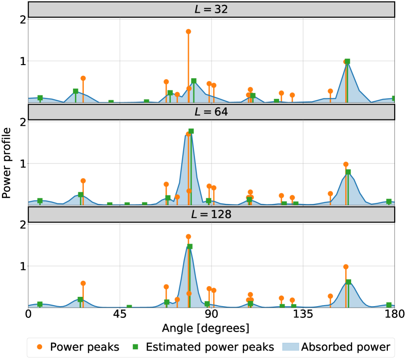
Probing phase. Without loss of generality, we assume that each codeword of the codebook is, to a certain extent, spatially directive, i.e., the resulting HRIS configuration maximizes the absorbed power only in correspondence of a (narrow) solid angle. This is relatively simple to realize by enforcing, e.g., some constraints on the design of the condewords in terms of half-power beamwidth of the corresponding radiation pattern of the HRIS. Therefore, by iteratively sweeping across all the codewords , the HRIS can scan, with a given spatial resolution, the three dimensional (3D) space and can detect network devices (the BS and the UEs) by using pilot signals emitted only by those devices. During this probing phase, the HRIS collects a set of power measurements, or equivalently a power profile, where each element is the power level sensed (measured) by the HRIS when using the codeword . As a result, the array response vectors in or can be estimated from . In practice, this boils down to detecting the peaks in and identifying the corresponding angular directions. By construction, in fact, the HRIS detects a power peak only if there is at least one transmitter in the direction synthesized by the HRIS beampattern (i.e., the considered codeword). The finer the angular selectivity of the HRIS, the longer the probing phase. Therefore a suitable compromise needs to be considered. An example of power profile as a function of the steering angle of the HRIS is reported in Fig. 5.
In particular, we assume that is a power peak in if it is greater than a given threshold . Let be the set of indexes corresponding to the power peaks. Then, depending on which devices transmit their pilot signals, and in (26) can be estimated as
| (31) |
where is a weight parameter that allows performing a hard () or a soft () combining of the power peaks in based on the actual measured power .
The end-to-end HRIS optimal configuration is first computed from (26) and is then projected onto the feasible set of discrete phase shifts in (30), which eventually yields the desired . The proposed probing phase is summarized in Algorithm 1.
Communication phase. Upon completion of the probing phase, the HRIS enters into the communication phase, which is aimed to assist the reliable transmission of data between the BS and the active UEs, as well as to probe the 3D space in order to discover new UEs. The communication phase is summarized in Algorithm 2. Once is obtained, the HRIS can easily aid the BS and the active UEs to communicate with each other. More challenging is the execution of the probing phase simultaneously with the communication phase. Therefore, hereafter we focus our attention on it.
To this end, we introduce the set of indices that do not correspond to any power peaks estimated during the probing phase. Then, we construct the following codebook for simultaneous probing and communication
| (32) |
whose codewords, after normalization and phase quantization, allow the HRIS to scan the 3D space, looking for new UEs, while keeping unaffected the beamsteering that corresponds to the UEs being already served.
It is worth mentioning that the probing phase for discovering new UEs does not replace the probing phase, executed on a regular basis, in Algorithm 1. This is because it is necessary to check whether the estimated directions of the HRIS still point towards the active UEs.
IV-B Codebook design
The probing and communication phases necessitate highly directive codebooks in order to scan the 3D space with a fine spatial resolution [19, 20]. To this end, we partition the total scanning angle into angular sectors with . Each codeword is, in particular, obtained as the solution of the following optimization problem
Problem 4 (Codebook design)
| s.t. | |||
where, with a slight abuse of notation, denotes the HRIS array response vector that points towards a UE at an angle with respect to the HRIS and that lies on the surface of a unit-radius sphere subtending the angle , and denotes a threshold value to be finely tuned at the design stage (as further discussed in Section V).
For fairness among the UEs, we consider that the radiation pattern of the HRIS across the generic th angular sector is as flat as possible in . Also, to minimize undesired reflections outside the angular range of interest, we enforce that the SNR of the UEs in the complementary set is below the threshold .
By defining , and , Problem 4 can be reformulated as follows.
Problem 5 (Codebook design using SDR)
| s.t. | |||
Problem 5 can be relaxed by ignoring the non-convex rank constraint, and by employing the semidefinite relaxation (SDR) method in CVX [21, 22]. Once the optimal solution of the relaxed version of Problem 5 is obtained, a suboptimal solution to Problem 4 is retrieved by using Gaussian randomization, which returns the desired codewords after projection onto the feasible set in (30).
V Performance Evaluation
To prove the feasibility of MARISA, we evaluate it in different scenarios and compare it against the SoA benchmark scheme, recently reported in [23], which relies upon a control channel to perform a centralized optimization. The simulation setup and the parameters are given in Table I. All results are averaged over simulation instances.
| Parameter | Value | Parameter | Value | Parameter | Value |
|---|---|---|---|---|---|
| GHz | |||||
| m | m | ||||
| dBm | , | dBm | |||
| 32 | |||||
| m-2 | m | m |
The network area is a square, and the BS and the HRIS (or the RIS) are located in the midpoints of two of its adjacent edges. The UEs are uniformly distributed in the network area, i.e., . To show the robustness of MARISA in realistic propagation scenarios, we relax the assumption of LoS propagation conditions and account for the non-line-of-sight (NLoS) paths as well. In particular, we consider the stochastic geometry based model in [24], which relates the geometric properties of the communication path in terms of the path length and height of the communicating devices (i.e., , , and ) in the presence of physical obstacles that may obstruct the links, which are referred to as blockers. The blockers are modeled as cylinders of height , diameter , and are distributed according to a Poisson point process (PPP) with intensity . Therefore, for each path in the network area, the probability of NLoS propagation is
| (33) |
The pathloss exponent for the LoS or NLoS paths are denoted by or , respectively.
As far as the optimization of the precoder at the BS is concerned, we assume perfect CSI at the BS. In particular, the configuration of the HRIS is assumed to be fixed by MARISA when optimizing the BS precoder. Therefore, the system is equivalent to a multiple-input single-output (MISO) channel given by the sum of the direct and reflected paths between the BS and each UE, where the HRIS is viewed as an additional fixed scatterer (whose optimization is obtained by using MARISA). For a fair comparison with the benchmark scheme in [23], the BS precoder is chosen as
| (34) |
where , and each column of is the equivalent end-to-end MISO channel between the BS and the corresponding UE.
It is worth mentioning that the performance of centralized deployments and MARISA depend on the overhead for channel estimation and reporting [25], and the overhead of the probing phase [26], respectively. These two solutions are very different from each other and a fair comparison of the associated overhead is postponed to a future research work.
V-A Comparison with the Centralized Deployment
We analyze the viability of self-configuring an HRIS by solving Problem 3 with perfect knowledge of the aggregate HRIS-UE channel and of the response vector of the HRIS towards the BS in (26). We refer to this design as the Oracle (O) scheme, since the channels are known already and do not need to be estimated.
Moreover, we analyze two solutions that assume real-valued (continuous) phase shifts: ) O-MARISA, which calculates , and ) O-weighted MARISA (O-wMARISA), which calculates . Specifically, O-MARISA estimates and only based on the direction of the paths that are assumed to have a unit gain, while O-wMARISA utilizes the direction and the gain of the paths.
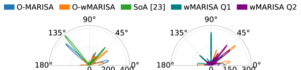
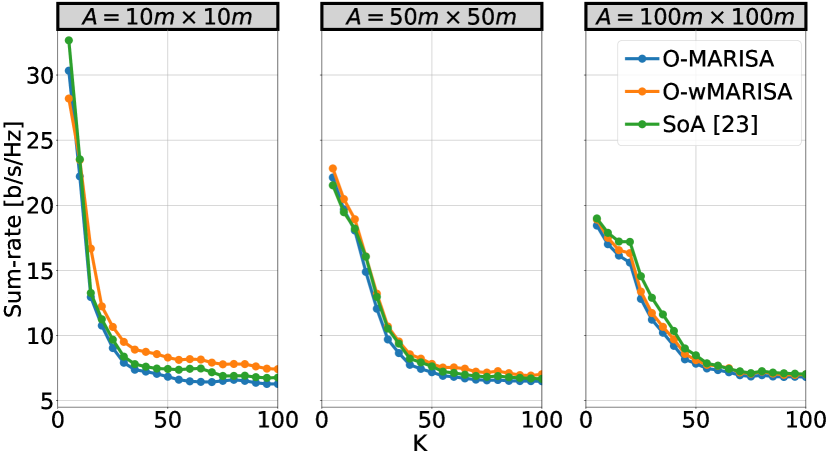
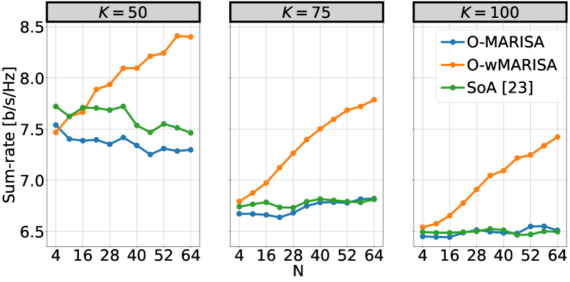
Figure 6 (left) shows a comparison of the HRIS configuration obtained by O-MARISA, O-wMARISA, and the SoA centralized solution in [23], which jointly optimizes the BS precoder and the RIS phase shifts by means of a control channel. While the SoA provides a very directive beampattern with few enhanced directions, both versions of O-MARISA result in a wider range of directions at the expense of a smaller gain due to the presence of multiple secondary lobes. Despite the different beampatterns, the sum-rates obtained by MARISA and the centralized benchmark, as shown in Fig. 7, are very similar. In particular, O-MARISA and the SoA provide a sum-rate that does not increase with the number of UEs, which hints to an interference-constrained scenario. Notably, O-wMARISA delivers better performance thanks to the weighting mechanism that strengthens the reflected paths with higher power gains. This behavior is further confirmed in Fig. 8, where the average sum-rate is analyzed against the number of HRIS elements and UEs . We see that, in this case, only O-wMARISA has a non-decreasing behavior regardless of the interference-constrained nature of the scenario, largely outperforming the SoA centralized solution in [23].
V-B Codebook-Based MARISA
In this section, we analyze the performance offered by MARISA under the realistic assumption that the HRIS optimizes its configuration through power measurements and by iteratively activating the beam patterns (codewords) in the codebook . Therefore, no apriori knowledge of the aggregate channel and of the response vector towards the BS is assumed. Also, the phase shifts applied by the HRIS belong to the discrete set in (30). The steering directions are computed based on the estimated peaks in the measured power profile . Supported by the previous case study, we analyze only the performance of wMARISA. Based on the estimated angular power profile , and are estimated from (31). The weights are set equal to , and , .
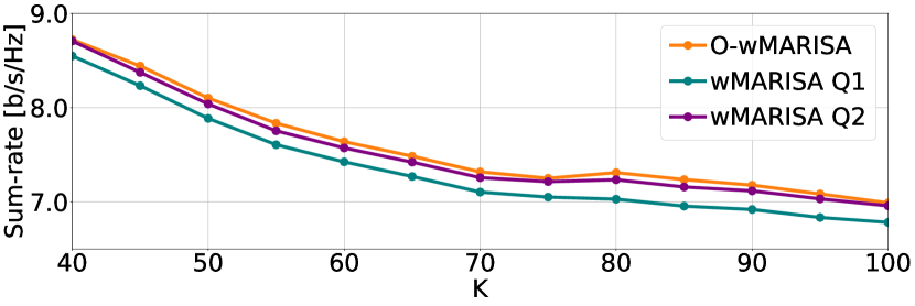
We consider two implementations for wMARISA, denoted by wMARISA Q1 and wMARISA Q2, which correspond to the wMARISA algorithm with the quantization levels and bits, respectively. The achievable average sum-rate is reported in Fig. 9. Relaxing the assumptions of perfect CSI and continuous phase shifts has only a limited impact on the sum-rate, which confirms the effectiveness of the approach proposed in Section II-B. As expected, the sum-rate worsens when one quantization bit is used, while two quantization bits offer good performance already.
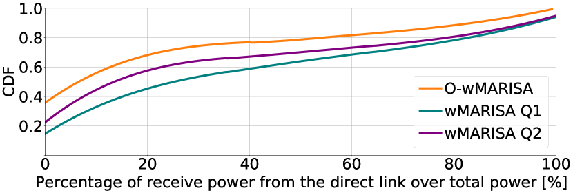
In Fig. 10, finally, we report the distribution of the percentage of power that every UE receives from the direct link with respect to the total received power (from the direct link and the reflected link). We note that O-wMARISA offers the highest power boost that originates from the reflect paths thanks to its ideal beamforming capabilities. On the other hand, wMARISA Q and Q are affected by quantization errors that lead to beampatterns with a more distributed power spread. Similar unwanted reflections can be seen in Fig. 6 (right), where the beampatterns obtained with O-wMARISA and wMARISA Q and Q are reported. However, these unwanted reflections have little impact on the sum-rate.
VI Related Works
In the last few years, RISs have drawn considerable interest from the scientific community due to their ability to turn uncontrollable propagation channels into controlled variables that can be optimized [27, 28]. A preliminary analysis of the achievable performance of an RIS is given in [29]. In particular, the authors formulate a joint optimization problem for optimizing the active beamforming (at the multi-antenna BS) and the passive beamforming configuration (at the RIS), and they demonstrate that RIS-based multiple-input multiple-output (MIMO) systems can achieve rate performance similar to legacy massive MIMO systems with fewer active antenna elements. The ideal case study with continuous phase shifts at the RIS is generalized to the case with discrete phase shifts in [16]. The authors prove the squared power gain with the number of reflecting elements even in the presence of phase quantization, but a power loss that depends on the number of phase-shift levels is observed [30]. In [23], the authors propose a practical algorithm to maximize the system sum mean squared error while jointly optimizing the transmit beamforming at MIMO BSs and the RIS configuration.
Other papers have recently considered the possibility of optimizing the RISs based on statistical CSI in order to relax the associated feedback overhead. A two-timescale transmission protocol is considered in [31] to maximize the achievable average sum-rate for an RIS-aided multiuser system under a general correlated Rician channel model, whereas [32] and [33] maximize the network sum-rate by means of the statistical characterization of the locations of the users, which does not require frequent updates of the RIS reconfiguration. These solutions, however, rely on the presence of a control channel.
A detailed analysis of an RIS-assisted multi-stream MIMO system is described in [34], where the authors formulate a joint optimization problem of the covariance matrix of the transmitted signal and the RIS phase shifts. An effective solution is obtained, which offers similar performance to SoA schemes but with limited computational complexity. The approach is generalized in [35] to discrete-valued constellation symbols. A comprehensive tutorial on RISs focused on optimization is available in [36].
None of above-mentioned works deals with self-configuring RIS-empowered networks without relying on a control channel, which is, on the other hand, the main contribution and novelty of the present paper.
VII Conclusions
RISs are an emerging clean-slate technology with the inherent potential of fundamentally reshaping the design and deployment of mobile communication systems. In this paper, we introduced MARISA, a Metasurface Absorption and Reflection solution for Intelligent Surfaces Applications, which treats HRISs as plug-and-play devices that are endowed with joint reflection and power-sensing capabilities. MARISA is built upon ) a new channel estimation model lato-sensu at the RIS and ) an autonomous RIS configuration methodology that is based only on CSI that can be locally estimated at the HRISs, without requiring an active control channel. Our results unveil promising performance trends: MARISA provides near-optimal sum-rates when compared to fully CSI-aware benchmark schemes that rely on a dedicated control channel.
References
- [1] O. Tsilipakos et al., “Toward intelligent metasurfaces: The progress from globally tunable metasurfaces to software-defined metasurfaces with an embedded network of controllers,” Advanced Optical Materials, vol. 8, no. 17, 2020.
- [2] M. Di Renzo, A. Zappone, M. Debbah, M.-S. Alouini, C. Yuen, J. de Rosny, and S. Tretyakov, “Smart Radio Environments Empowered by Reconfigurable Intelligent Surfaces: How It Works, State of Research, and The Road Ahead,” IEEE Journal on Selected Areas in Communications, vol. 38, no. 11, pp. 2450–2525, 2020.
- [3] E. C. Strinati, G. C. Alexandropoulos, H. Wymeersch, B. Denis, V. Sciancalepore, R. D’Errico, A. Clemente, D.-T. Phan-Huy, E. De Carvalho, and P. Popovski, “Reconfigurable, intelligent, and sustainable wireless environments for 6g smart connectivity,” IEEE Communications Magazine, vol. 59, no. 10, pp. 99–105, 2021.
- [4] M. Di Renzo et al., “Smart radio environments empowered by reconfigurable AI meta-surfaces: an idea whose time has come,” EURASIP J. Wireless Commun. Net., vol. 2019, no. 1, pp. 1–20, May 2019.
- [5] O-RAN Alliance, “O-RAN Use Cases and Deployment Scenarios,” White Paper, Feb. 2020. [Online]. Available: https://tinyurl.com/35d56dyu
- [6] A. Albanese, G. Encinas Lago, V. Sciancalepore, X. Costa-Pérez, D.-T. Phan-Huy, and R. Stéphane, “RIS-Aware Indoor Network Planning: The Rennes Railway Station Case,” in ICC 2022 - 2022 IEEE International Conference on Communications (ICC), 2022, pp. 1–7.
- [7] E. Björnson, Ö. Özdogan, and E. G. Larsson, “Reconfigurable intelligent surfaces: Three myths and two critical questions,” IEEE Communications Magazine, vol. 58, no. 12, pp. 90–96, 2020.
- [8] A. Albanese, V. Sciancalepore, and X. Costa-Pérez, “First Responders Got Wings: UAVs to the Rescue of Localization Operations in Beyond 5G Systems,” IEEE Communications Magazine, vol. 59, no. 11, pp. 28–34, 2021.
- [9] G. C. Alexandropoulos, N. Shlezinger, I. Alamzadeh, M. F. Imani, H. Zhang, and Y. C. Eldar, “Hybrid reconfigurable intelligent metasurfaces: Enabling simultaneous tunable reflections and sensing for 6G wireless communications,” arXiv preprint arXiv:2104.04690, 2021.
- [10] A. E. Lamminen, J. Saily, and A. R. Vimpari, “60-GHz patch antennas and arrays on LTCC with embedded-cavity substrates,” IEEE Transactions on Antennas and Propagation, vol. 56, no. 9, pp. 2865–2874, 2008.
- [11] J.-H. Li, X. Liao, and C. Chu, “A novel thermistor-based RF power sensor with wheatstone bridge fabricating on MEMS membrane,” Journal of Microelectromechanical Systems, vol. 29, no. 5, pp. 1314–1321, 2020.
- [12] M. Yasir, M. Aldrigo, M. Dragoman, A. Dinescu, M. Bozzi, S. Iordanescu, and D. Vasilache, “Integration of antenna array and self-switching graphene diode for detection at 28 GHz,” IEEE Electron Device Letters, vol. 40, no. 4, pp. 628–631, 2019.
- [13] R. Bhattacharya, V. Aggarwal, A. Gupta, T. Kukal, and S. Aniruddhan, “An 8-channel varactor-less 28-GHz front end with 7-Bit resolution 340 RTPS for 5G RF beamformers,” IEEE Transactions on Circuits and Systems II: Express Briefs, vol. 66, no. 12, pp. 1937–1941, 2019.
- [14] K. Shen and W. Yu, “Fractional programming for communication systems–—Part I: Power control and beamforming,” IEEE Transactions on Signal Processing, vol. 66, no. 10, pp. 2616–2630, 2018.
- [15] A. Alkhateeb, Y.-H. Nam, M. S. Rahman, J. Zhang, and R. W. Heath, “Initial beam association in millimeter wave cellular systems: Analysis and design insights,” IEEE Transactions on Wireless Communications, vol. 16, no. 5, pp. 2807–2821, 2017.
- [16] Q. Wu and R. Zhang, “Beamforming optimization for wireless network aided by intelligent reflecting surface with discrete phase shifts,” IEEE Transactions on Communications, vol. 68, no. 3, pp. 1838–1851, 2020.
- [17] J. He, H. Wymeersch, T. Sanguanpuak, O. Silven, and M. Juntti, “Adaptive beamforming design for mmWave RIS-aided joint localization and communication,” in 2020 IEEE Wireless Communications and Networking Conference Workshops (WCNC), 2020, pp. 1–6.
- [18] T. Boles, J. Brogle, D. Hoag, and D. Curcio, “AlGaAs PIN diode multi-octave, mmW switches,” in 2011 IEEE International Conference on Microwaves, Communications, Antennas and Electronic Systems (COMCAS 2011). IEEE, 2011, pp. 1–5.
- [19] F. Devoti, V. Sciancalepore, I. Filippini, and X. Costa-Pérez, “PASID: Exploiting Indoor mmWave Deployments for Passive Intrusion Detection,” in IEEE INFOCOM 2020-IEEE Conference on Computer Communications. IEEE, 2020, pp. 1479–1488.
- [20] A. Albanese, P. Mursia, V. Sciancalepore, and X. Costa-Pérez, “PAPIR: Practical RIS-aided Localization via Statistical User Information,” in 2021 IEEE 22nd International Workshop on Signal Processing Advances in Wireless Communications (SPAWC), 2021, pp. 531–535.
- [21] Z.-Q. Luo, W.-K. Ma, A. M.-C. So, Y. Ye, and S. Zhang, “Semidefinite relaxation of quadratic optimization problems,” IEEE Signal Processing Magazine, vol. 27, no. 3, pp. 20–34, 2010.
- [22] M. Grant and S. Boyd, “CVX: Matlab software for disciplined convex programming, version 2.1,” http://cvxr.com/cvx, Mar. 2014.
- [23] P. Mursia, V. Sciancalepore, A. Garcia-Saavedra, L. Cottatellucci, X. Costa-Pérez, and D. Gesbert, “RISMA: Reconfigurable intelligent surfaces enabling beamforming for IoT massive access,” IEEE Journal on Selected Areas in Communications, vol. 39, no. 4, pp. 1072–1085, 2021.
- [24] M. Gapeyenko, A. Samuylov, M. Gerasimenko, D. Moltchanov, S. Singh, M. R. Akdeniz, E. Aryafar, N. Himayat, S. Andreev, and Y. Koucheryavy, “On the temporal effects of mobile blockers in urban millimeter-wave cellular scenarios,” IEEE Transactions on Vehicular Technology, vol. 66, no. 11, pp. 10 124–10 138, 2017.
- [25] A. Zappone, M. Di Renzo, F. Shams, X. Qian, and M. Debbah, “Overhead-aware design of reconfigurable intelligent surfaces in smart radio environments,” IEEE Transactions on Wireless Communications, vol. 20, no. 1, pp. 126–141, 2020.
- [26] I. Rouissi, J. M. Floc’h, H. Rmili, and H. Trabelsi, “Design of a frequency reconfigurable patch antenna using capacitive loading and varactor diode,” in 2015 9th European Conference on Antennas and Propagation (EuCAP). IEEE, 2015, pp. 1–4.
- [27] H. Liu, J. Zhang, Q. Wu, H. Xiao, and B. Ai, “ADMM Based Channel Estimation for RISs Aided Millimeter Wave Communications,” IEEE Communications Letters, vol. 25, no. 9, pp. 2894–2898, 2021.
- [28] R. Liang, J. Fan, and J. Yue, “A cascaded multi-IRSs beamforming scheme in mmWave communication systems,” IEEE Access, vol. 9, pp. 99 193–99 200, 2021.
- [29] Q. Wu and R. Zhang, “Intelligent reflecting surface enhanced wireless network via joint active and passive beamforming,” IEEE Transactions on Wireless Communications, vol. 18, no. 11, pp. 5394–5409, 2019.
- [30] I. Yildirim, A. Uyrus, and E. Basar, “Modeling and analysis of reconfigurable intelligent surfaces for indoor and outdoor applications in future wireless networks,” IEEE Transactions on Communications, vol. 69, no. 2, pp. 1290–1301, 2021.
- [31] M.-M. Zhao, Q. Wu, M.-J. Zhao, and R. Zhang, “Intelligent reflecting surface enhanced wireless networks: Two-timescale beamforming optimization,” IEEE Transactions on Wireless Communications, vol. 20, no. 1, pp. 2–17, 2020.
- [32] A. Abrardo, D. Dardari, and M. Di Renzo, “Intelligent reflecting surfaces: Sum-rate optimization based on statistical position information,” IEEE Transactions on Communications, vol. 69, no. 10, pp. 7121–7136, 2021.
- [33] K. Zhi, C. Pan, H. Ren, and K. Wang, “Statistical CSI-based design for reconfigurable intelligent surface-aided massive MIMO systems with direct links,” IEEE Wireless Communications Letters, vol. 10, no. 5, pp. 1128–1132, 2021.
- [34] N. S. Perović, L.-N. Tran, M. Di Renzo, and M. F. Flanagan, “Achievable rate optimization for MIMO systems with reconfigurable intelligent surfaces,” IEEE Transactions on Wireless Communications, vol. 20, no. 6, pp. 3865–3882, 2021.
- [35] N. S. Perović, L.-N. Tran, M. Di Renzo, and M. F. Flanagan, “Optimization of RIS-aided MIMO systems via the cutoff rate,” IEEE Wireless Communications Letters, pp. 1–1, 2021.
- [36] Q. Wu, S. Zhang, B. Zheng, C. You, and R. Zhang, “Intelligent reflecting surface-aided wireless communications: A tutorial,” IEEE Transactions on Communications, vol. 69, no. 5, pp. 3313–3351, 2021.