0cm \titlecontentschapter[1.25cm] \contentslabel[\thecontentslabel]1.25cm \thecontentspage \titlecontentssection[1.25cm] \contentslabel[\thecontentslabel]1.25cm \thecontentspage [] \titlecontentssubsection[1.25cm] \contentslabel[\thecontentslabel]1.25cm \thecontentspage [] \titlecontentslsection[0em] \titlecontentslsubsection[.5em] \DeclareAcronym3Gshort = 3G , long = third generation \DeclareAcronym2Gshort = 2G , long = second generation \DeclareAcronym1Gshort = 1G , long = first generation \DeclareAcronymETshort = ET , long = Einstein Telescope \DeclareAcronymCEshort = CE , long = Cosmic Explorer \DeclareAcronymKAGRAshort = KAGRA , long = Japanese underground gravitational wave detector \DeclareAcronymLIGOshort = LIGO , long = Laser Interferometer Gravitational wave Observatory \DeclareAcronymaLIGOshort = aLIGO , long = advanced LIGO \DeclareAcronymVirgoshort = Virgo , long = Virgo gravitational wave detector \DeclareAcronymAdVirgoshort = AdVirgo , long = advanced Virgo detector \DeclareAcronymLIGOIndiashort = LIGO India , long = a copy of the advanced LIGO detectors placed in India \DeclareAcronymUSAshort = USA , long = United States of America \DeclareAcronyma+LIGOshort = LIGO A+ , long = upgraded advanced Laser Interferometer Gravitational wave Observatory \DeclareAcronymAdVirgo+short = AdVirgo+ , long = upgraded advanced Virgo detector \DeclareAcronymVoyagershort = Voyager , long = Voyager, a detector with 3G technology in the 2G infrastructure \DeclareAcronymNEMOshort = NEMO , long = Neutron Star Extreme Matter Observatory, a plan for a high frequency GW detector in a 2G scale facility \DeclareAcronym2.5Gshort = 2.5G , long = an improved version of the second detector generation with incrementally new technology \DeclareAcronymRaDshort = R&D , long = research and development \DeclareAcronymGWshort = GW , short-plural = s , long = gravitational waves \DeclareAcronymGWDshort = GWD , short-plural = s, long = gravitational wave detector \DeclareAcronymGWICshort = GWIC , long = gravitational wave international committee \DeclareAcronymGWACshort = GWAC , long = gravitational wave agency correspondents \DeclareAcronymMLshort = ML , long = maturity level \DeclareAcronymET-LFshort = ET-LF , long = Einstein Telescope low frequency interferometer \DeclareAcronymET-HFshort = ET-HF , long = Einstein Telescope high frequency interferometer \DeclareAcronymFPshort = FP , long = Fabry-Perot cavity, a linear optical resonator \DeclareAcronymNNshort = NN , long = Newtonian noise, a gravitational coupling of surrounding mass (especcially of moving mass due to seismic waves or infra-sound) to the mirrors \DeclareAcronymSQZshort = SQZ , long = squeezing, a technology to modify quantum noise distribution over the two quadratures of the light field \DeclareAcronymPRshort = PR , long = Power Recycling \DeclareAcronymSRshort = SR , long = Signal Recycling \DeclareAcronymQRPNshort = QRPN , long = quantum radiation pressure noise \DeclareAcronymSNshort = SN , long = shot noise \DeclareAcronymUHVshort = UHV , long = Ultra High Vacuum \DeclareAcronymNSFshort = NSF , long = National Science Foundation \DeclareAcronymNISTshort = NIST , long = National Institute of Standards and Technology \DeclareAcronymJLabshort = JLab , long = Jefferson Lab \DeclareAcronymCERNshort = CERN , long = European Centre for nuclear research \DeclareAcronymCE2short = CE2 , long = Cosmic Explorer phase 2 \DeclareAcronymCE1short = CE1 , long = Cosmic Explorer phase 1, using 2G technology \DeclareAcronymDSshort = DS , long = Design Study \DeclareAcronymMCzshort = MCz , long = magnetically assisted Czochralski \DeclareAcronymITMshort = ITM , long = Inner Test mass \DeclareAcronymETMshort = ETM , long = End Test Mass \DeclareAcronymHeraeusshort = Heraeus , long = a German company producing ultra-pure fused silica glass \DeclareAcronymTLSshort = TLS , long = two level system \DeclareAcronymAlGaAs/GaAsshort = AlGaAs/GaAs , long = Aluminium-Gallium-Arsenide / Gallium Arsenide \DeclareAcronymGaP/AlGaPshort = GaP/AlGaP , long = Gallium Phosphide / Alluminium Gallium Phosphide \DeclareAcronymTshort = , long = Temperature \DeclareAcronymLshort = L , long = interferometer arm length \DeclareAcronymwshort = , long = laser beam radius \DeclareAcronymphishort = , long = mechanical loss angle \DeclareAcronymdshort = , long = coating thickness \DeclareAcronymfshort = , long = frequency \DeclareAcronymA+short = A+ , long = the upgraded advanced interferometer generation \DeclareAcronymCCRshort = CCR , long = Center for Coatings Research, Stanford \DeclareAcronymLSCshort = LSC , long = LIGO Scientific Collaboration \DeclareAcronymLVCshort = LVC , long = LIGO Virgo Collaboration \DeclareAcronymGEOshort = GEO , long = the GEO collaboration \DeclareAcronymU.K.short = U.K. , long = United Kingdom \DeclareAcronymLMAshort = LMA , long = Laboratoire des Matériaux Avancés \DeclareAcronymILMshort = ILM , long = Insitut Lumière Materiè \DeclareAcronymANRshort = ANR , long = Agence nationale de la recherche \DeclareAcronymViSIONsshort = ViSIONs , long = a coating project funded by \acs*ANR \DeclareAcronymIBSshort = IBS , long = ion-beam sputtering \DeclareAcronymLIGO Labshort = LIGO Lab , long = laboratory running the LIGO project \DeclareAcronymYshort = Y , long = the mechanical admittance \DeclareAcronymomegashort = , long = the angular frequency \DeclareAcronymk_bshort = , long = the Boltzmann constant \DeclareAcronymDNAshort = , long = Fourier components of the displacement of the system \DeclareAcronymFNAshort = , long = Fourier components of the force leading to the displacement of the system \DeclareAcronymCLIOshort = CLIO , long = cryogenic 100 m prototype interferometer in the Japanese Kamioka mine \DeclareAcronymLIDARshort = LIDAR , long = light detection and ranging \DeclareAcronymPSLshort = PSL , short-plural = s, long = pre-stabilized laser system \DeclareAcronymHPLshort = HPL , short-plural = s , long = high power laser \DeclareAcronymAEIshort = AEI , long = Albert Einstein Institute \DeclareAcronymLZHshort = LZH , long = Laser Zentrum Hannover \DeclareAcronymArtemisshort = Artemis , long = \DeclareAcronymAlphanovshort = Alphanov , long = Centre Technologique Optique et Lasers, France \DeclareAcronymICRRshort = ICRR , long = institute for cosmic research, University Tokyo \DeclareAcronymMitsubishishort = Mitsubishi , long = Japanese company \DeclareAcronymLG33short = , long = Laguerre Gauss Mode 33 \DeclareAcronymIFOshort = IFO , long = Interferometer \DeclareAcronymNufernshort = Nufern , long = Fibre laser company \DeclareAcronymMOPAshort = MOPA , long = master oscillator power amplifier \DeclareAcronymMITshort = MIT , long = Massachusetts Institute of Technology \DeclareAcronymneoVAN4Sshort = neoVAN 4S , long = a solid state laser of the German company NEOLASE \DeclareAcronymIITshort = IIT , long = Indian institute of technology \DeclareAcronymQNDshort = QND , long = Quantum Non-Demolition \DeclareAcronymSQLshort = SQL , long = standard quantum limit \DeclareAcronymSUSshort = SUS , short-plural = s , long = suspension system, long-plural = s , \DeclareAcronymSASshort = SAS , short-plural = s , long = Seismic attenuation system \DeclareAcronymHEPIshort = HEPI , long = hydraulic external pre-isolator \DeclareAcronymSAshort = SA , long = Super Attenuator \DeclareAcronymFEAshort = FEA , long = finite element analysis \DeclareAcronymGEO600short = GEO 600 , long = the German/British 600m gravitational wave detector in Germany \DeclareAcronymGWADWshort = GWADW , long = Gravitational Wave Advanced Detector Workshop \DeclareAcronymLASTIshort = LASTI , long = LIGO advanced system test interferometer at MIT \DeclareAcronymSISshort = SIS , long = seismic isolation system \DeclareAcronymAWCshort = AWC , long = Active Wavefront Control \DeclareAcronymTCSshort = TCS , long = thermal compensation system \DeclareAcronymEOMshort = EOM , short-plural = s, long = electro optic modulator \DeclareAcronymIFIshort = IFI , long = input Faraday isolator \DeclareAcronymTGGshort = TGG , long = Terbium gallium garnet \DeclareAcronymIMCshort = IMC , long = input Mode cleaner \DeclareAcronymOFIshort = OFI , long = Output Faraday isolator \DeclareAcronymFCshort = FC , short-plural = s, long = filter cavity \DeclareAcronymOMCshort = OMC , short-plural = s, long = output mode cleaner \DeclareAcronymBHDshort = BHD, short-plural = s , long = balanced homodyne detector \DeclareAcronymRFshort = RF , long = radio frequency \DeclareAcronymSPIshort = SPI , long = suspension point interferometer \DeclareAcronymFIshort = FI , short-plural = s,long = Faraday isolator \DeclareAcronymGWINCshort = GWINC , long = Gravitational wave interferometer noise calculator \DeclareAcronymFFTshort = FFT , long = fast Fourier transform \DeclareAcronymSISbshort = SIS , long = Stationary Interferometer Simulation tool \DeclareAcronymOSCARshort = OSCAR , long = optical FFT code to simulate Fabry Perot cavities with arbitrary mirror profiles \DeclareAcronymDarkFshort = DarkF , long = an optical simulation code in FORTRAN 90 \DeclareAcronymMISTshort = MIST , long = Matlab based fast modal simulation of paraxial optical systems \DeclareAcronymFinesseshort = Finesse , long = Frequency-domain interferometer simulation with higher-order spatial modes \DeclareAcronymOptickleshort = Optickle , long = a general model for the electro-opto-mechanical part of a GW detector \DeclareAcronymSimPlantshort = SimPlant , long = virtual interferometer for commissioning \DeclareAcronymIfoCADshort = IfoCAD , long = 3D ray tracing tool using Gaussian beams \DeclareAcronymCADshort = CAD , long = computer aided design \DeclareAcronymOptoCADshort = OptoCAD , long = 2D ray tracing tool using Gaussian beams \DeclareAcronymMIMOshort = MIMO , long = multiple in, multiple out \DeclareAcronym3Dshort = 3D , long = three dimensional \DeclareAcronymDARMshort = DARM , long = differential arm motion \DeclareAcronymRMSshort = RMS , long = root mean square \DeclareAcronymFPGAshort = FPGA , short-plural = s, long = field programmable gate array \DeclareAcronymGPUshort = GPU , short-plural = s,long = graphics processing unit \DeclareAcronymSNRshort = SNR , short-plural = s, long = signal to noise ratio \DeclareAcronymBNSshort = BNS , long =binary neutron star \DeclareAcronymGRshort = GR , long = general relativity \DeclareAcronymMCMCshort = MCMC , long = Markov-Chain-Monte-Carlo method \DeclareAcronymVCRaDshort = VCR&D , long = Virgo Coating R&D collaboration \DeclareAcronymUWSshort = UWS , long = University of the West of Scotland \DeclareAcronymMBEshort = MBE, long = Molecular Beam Epitaxy \DeclareAcronymGeNSshort = GeNS , long = Gentle Nodal Support Sytem \DeclareAcronymCSIROshort = CSIRO , long = Commonwealth Scientific and Industrial Research Organisation (an Australian federal government agency responsible for scientific research) \DeclareAcronymANUshort = ANU , long = Australian National University \DeclareAcronymCNRSshort = CNRS , long = Centre national de la recherche scientifique (the French national research centre for scientific research
.
3G R&D
R&D for the next generation of ground-based gravitational-wave detectors
GWIC
April 2021
DETECTOR RESEARCH AND DEVELOPMENT SUBCOMMITTEE
David McClelland, Australian National University, Australia (Co-chair)
Harald Lueck, AEI, Hannover, Germany (Co-chair)
Rana Adhikari, Caltech, USA
Masaki Ando, University of Tokyo, Japan
GariLynn Billingsley, Caltech, USA
Geppo Cagnoli, ILM, Lyon, France
Matt Evans, MIT, USA
Martin Fejer, Stanford University, USA
Andreas Freise, University of Birmingham, UK
Paul Fulda, University of Florida, USA
Eric Genin, Virgo, Italy
Gabriela González, Louisiana State University, USA
Jan Harms, Università degli Studi di Urbino, Italy
Stefan Hild, University of Glasgow, UK
Giovanni Losurdo, INFN Pisa, Italy
Ian Martin, University of Glasgow, UK
Anil Prabhakar, IIT Madras, India
Stuart Reid, University of Strathclyde, UK
Fulvio Ricci, Università La Sapienza, and INFN Roma, Italy
Norna Robertson, Caltech, USA
Jo van den Brand, Nikhef, Netherlands
Benno Willke, AEI, Hannover, Germany
Mike Zucker, MIT, USA
STEERING COMMITTEE
Michele Punturo, INFN Perugia, Italy (Co-chair)
David Reitze, Caltech, USA (Co-chair)
Peter Couvares, Caltech, USA
Stavros Katsanevas, European Gravitational Observatory
Takaaki Kajita, University of Tokyo, Japan
Vicky Kalogera, Northwestern University, USA
Harald Lueck, AEI, Germany
David McClelland, Australian National University, Australia
Sheila Rowan, University of Glasgow, UK
Gary Sanders, Caltech, USA
B.S. Sathyaprakash, Penn State University, USA and Cardiff University, UK
David Shoemaker, MIT, USA (Secretary)
Jo van den Brand, Nikhef, Netherlands
Gravitational Wave International Committee
This document was produced by the GWIC 3G Committee, the GWIC 3G R&D Team and the International 3G Science Team Consortium
Final release, April 2021
ADDITIONAL AUTHORS
Alessandro Bertolini, Nikhef, Netherlands
Stefan Danilishin, Maastricht University, and Nikhef, Netherlands
Francesco Fidecaro, University of Pisa, and INFN Pisa, Italy
Gianluca Gemme, INFN Genova, Italy
Giles Hammond, SUPA, University of Glasgow, UK
James Lough, AEI, and Institut fur Gravitationsphysik der Leibniz Universitat Hannover, Germany
Ettore Majorana, Università di Roma, Italy
Ando Massaki, The University of Tokyo, Japan
Joshua Smith, California State University Fullerton, California, USA
Helios Vocca, University of Perugia, and INFN Perugia, Italy
Krishna Venkateswara, University of Washington, USA
Robert L. Ward, Australian National University, Australia
Kazuhiro Yamamoto, University of Toyama, Japan
Chapter 1 Introduction
In this report we review the \acRaD needed to construct massive new facilities, far larger then current facilities, and operate in them detectors with "\ac3G" sensitivity. The new \ac3G facilities will be designed to accommodate successive generations of detectors with increasing sensitivity as the technology evolves and new ideas emerge as has happened with existing facilities. The infrastructures which initially housed the \ac1G \acLIGO [1] and \acVirgo [2] detectors, now house the second generation \acaLIGO [3] detectors, (\acAdVirgo [4] along with LIGO India and KAGRA. There are plans for further upgrades to these \ac2G detectors - \aca+LIGO, \acAdVirgo+ [5, 6]. Further more completely new detectors, such as \acVoyager[7] and NEMO [8] may later be installed in the existing facilities or facilities of a similar scale . These detectors are referred to as 2.5G class detectors.
Section 2 will cover the \acRaD needed to select suitable sites and build such large, long-lifetime facilities in a cost efficient way. The remainder of the chapter will focus on the \acRaD required to deliver the first detectors operational in these \ac3G facilities. Currently, there are two main concepts for these detectors, \acfET [9], a 10-km triangular underground detector, and \acfCE [10], a 40-km above-ground L-shaped detector. These concepts, along with Voyager are highlighted in Box 1.
Currently (circa 2021) Advanced LIGO and Advanced Virgo have completed the third observing run. These detectors are being upgraded toward LIGO A+ and AdVirgo+ operations and possible modest sensitivity improvements will be implemented beyond these designs. Following these detector upgrades by about 10 years we envision a network of new detectors, CE and ET in longer-baseline \ac3G facilities, along with detectors that use \ac3G technology within 2G scale facilities.
The first instruments to be installed in the new \ac3G Observatories will be 10 to 20 times more sensitive than the current \ac2G instruments above 100 Hz (Fig. 1.1). The improvement factor exceeds 100 around 10 Hz and thousands below 10 Hz. The key parameters for \ac2G and \ac3G instruments are summarized in Table 1.1. The \ac3G facilities are being designed with lifetimes on the order of 50 years in order to house detectors far more sensitivity that the initially proposed ET and CE designs. Strategies for \ac3G will be modified according to observations made with current detectors, evolution in the science case, technology readiness and funds available. This \acGWIC \ac3G report represents a milestone community vision for the future of ground based gravitational wave observations.
Planning for the \ac3G detectors began more than 20 years before they were envisioned to become operative. This was based on experience with past and current detectors, for which there was a lead time of 15 years or more from conception to operation. Assuming a 2035 start date for initial \ac3G operations, preceded by five years of construction and five years of commissioning, it is likely that only technologies with mature \acRaD in 2025 will feed into final design and engineering for the initial \ac3G detectors.
Despite their differences in design, the \ac3G detectors \acET and \acCE rely on similar ‘enabling technologies’ – the main pillars on which the predictions of sensitivity are based. These technologies are used to mitigate ‘fundamental noise sources’ affecting the instruments, in particular: Quantum noise associated with the laser light fields is modified by high laser power, quantum squeezing, massive mirrors and interferometer topology; Thermal noise in mirror substrates, coatings and suspensions is modified by temperature and material properties (and their behaviour as a function of temperature); and Newtonian noise caused by the gravitational forces of moving masses (such as air, the ground, and machinery) is modified by the location of the sites and subtraction schemes. Similarly supporting technologies such as control systems and methods to mitigate a forest of technical noise are issues common to all interferometer designs.
These considerations are interdependent and have implications for the detector designs. For example, using low temperatures to reduce Brownian noise requires a departure from the fused silica optics used in Advanced LIGO and Advanced Virgo. Sapphire and Silicon are promising low temperature materials. Silicon would require changing the operating wavelength to 1.5 – 2 µm, necessitating the development of a new suite of light sources, optical components and detectors. Considering the material properties as a function of temperature and wavelength as well as the ability to handle high optical power while minimizing noise during heat extraction from the core optics leads to four possible operating temperatures: room temperature and the cryogenic temperatures of 123 K, 20 K and below 5 K. At this time we are not in a position to make the choice. The final technologies for the first interferometers in the \ac3G facilities will depend on \acRaD progress across the various subsystems. It will require intensive sensitivity trade studies informed by science goals and is beyond the scope of this report. Indeed different collaborations may choose different optimizations. In a conservative scenario, the first instruments could use technologies already proven in \ac2G facilities. This is the option currently favoured by the Cosmic Explorer collaboration, referred to as \acsCE1.

In this chapter, we assess the state of \acRaD for \ac3G enabling and supporting technologies toward readiness before the end of the decade while also looking ahead to the \acRaD that will continue as a necessary preparation for subsequent \ac3G upgrades. Each section contains an outlook for the activity and recommendations on how to best progress the \acRaD globally. We begin by presenting a brief overview on the basics of gravitational wave detection, and introduce the main subsystems that make up an interferometer. Then in section 2 we address requirements and design aspects of the \ac3G infrastructure.
In subsequent sections we consider the state of the art in the various technologies, the \acRaD needed in each area, the level of resources needed (broadly bracketed as high, medium, low), and how the \acRaD should be focused in order to deliver fully tested subsystems for timely installation in new \ac3G facilities. The analysis suggests prototyping \ac3G technology including new test facilities and use of existing long baseline facilities.
Section 3 describes Newtonian noise and its connection with facility choices and reliance on modelling and subtraction schemes. Section 4 covers suspensions and seismic isolation systems while Section 5 addresses cryogenics. Sections 6 and 7 describe the closely related subjects of core optics and coatings. A common theme among these chapters is thermal noise, described in Box 1.0.2, which is the primary consideration for many choices in optics, coatings, suspensions, and operating temperature. Section 8 reviews Light sources, both lasers and squeezed state generators. This is followed in Section 9 with an examination of quantum enhancement techniques. In addition to the fundamental noises described above, a myriad of technical noise sources and control issues can limit interferometer performance: parametric instabilities, scattered light, and noise originating from auxiliary optics and control systems. The current state of the art in these areas, \acRaD needed, and coordination for 3G are reviewed in Sections 10 and 11. Finally, Section 12 describes plans for accurately calibrating the instruments to levels that will enable the dramatic science described in the first part of this report. We end in the summary by proposing four broad recommendations designed to optimise global \acRaD resources in order to make timely progress.
| aLIGO / AdV | A+/V+ | KAGRA | CE 1 | CE 2 | ET-LF | ET-HF | |
| Arm Length [km] | 4 / 3 | 4 / 3 | 3 | 40 | 40 | 3x10∗ | 3x10∗ |
| Mirror Mass [kg] | 40 / 42 | 40 | 23 | 440 | 470 | 211 | 200 |
| Mirror Material | silica | silica | sapphire | silica | silicon | silicon | silica |
| Mirror Temp [K] | 295 | 295 | 20 | 295 | 123 | 10 | 290 |
| Suspension Fiber | 0.6m/0.7m | 0.6m | 0.35m | 2m | 2m | 2m | 0.6m |
| SiO2 | SiO2 | Al2O3 | SiO2 | Si | Si | SiO2 | |
| Fiber Type | Fiber | Fiber | Fiber | Fiber | Ribbon | Fiber | Fiber |
| Input Power [W] | 125 | 125 | 70 | 140 | 280 | 3 | 500 |
| Arm Power [kW] | 710 / 700 | 750 | 350 | 1500 | 3000 | 18 | 3000 |
| Wavelength [nm] | 1064 | 1064 | 1064 | 1064 | 2000 | 1550 | 1064 |
| \acsNN Suppression | 1 | 1 | 1 | 2 | 10 | 1 | 1 |
| Beam Size [cm] | (5.5/6.2) / 6 | 5.5/6.2 | 3.5/3.5 | 10/13 | 14/18 | 9/9 | 12/12 |
| \acsSQZ Factor [dB] | 0 | 6 | foreseen | 6 | 10 | 10 | 10 |
| Filter Cavity | none | 300 | unknown | 4000 | 4000 | 10000 | 500 |
| Length [m] |
1.1 Gravitational Wave Detection Basics
Gravitational waves induce tiny changes in separation between widely spaced ‘test masses’. The instrumental challenge is to measure these tiny changes. Audio band detectors use laser interferometry, where the interferometer mirrors are the test masses at the ends of long baselines whose length changes are measured. The basis of all present and next generation gravitational wave detectors is a dual recycled Fabry-Perot arm cavity Michelson interferometer as sketched in figure 1.2.
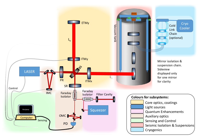
Being quadrupolar radiation, a passing \acGW alternately expands and then contracts one arm (e.g. ) of the interferometer whilst it contracts and then expands the arm perpendicular to it (). The effect is extremely small: expressed as a relative length change, , it is less than ! The arm cavities increase the phase change imposed on the light. Interfering the single frequency light beams from the two arms at the beamsplitter (BS) cancels common noise whilst the signal adds. Extra elements (\acPR and \acSR mirrors, squeezing, filter cavities etc) further increase sensitivity and optimise the response [16]. The core optics (test mass mirrors) are hung from sophisticated suspensions systems as indicated in figure 1.2 (in the vacuum tank on the right) so that, above resonance frequencies, they are effectively free to move [17]. The main optics can be cooled to cryogenic temperatures to minimise thermal noise. In addition to the core optics there are a host of auxiliary optics to condition and match (in angle and size) the laser beam into the interferometer and the signal field out of the interferometer and into the photodetection system.
Once technical noises, such as laser frequency and intensity noise, acoustic noise and seismic noise, have been reduced there are three basic processes limiting the interferometer sensitivity: thermal, Newtonian (gravity gradient), and quantum noise. In Figure 1.3 we demonstrate the typical frequency distributions of these processes using the A+ design curve [18]

Thermal noise 1.0.2,[19] is produced by random displacements of the mirror surfaces in response to thermally fluctuating stresses in the mirror coatings, substrates, and suspensions and it typically dominates at midband frequencies (ca. 50-200 Hz). Quantum noise can be roughly divided into \acQRPN and quantum phase noise or \acSN [20]. \acQRPN, or quantum back-action noise, arises from the random buffeting of the suspended interferometer mirrors by the quantum mechanical amplitude fluctuations of the light field being used to sense the arm-length. Shot noise results from quantum phase uncertainty: there is a limit to how well the phase difference between two light fields returning from the interferometers arms can be determined. Radiation pressure noise dominates at low frequencies (ca. 10Hz to 50 Hz) while shot noise dominates at higher frequencies (above ca. 200 Hz). The standard quantum limit is the noise floor for which the \acQRPN and shot noise are equal at a given power level (typically around 100 Hz). \Ac*NN arises from the direct gravitational forces exerted on the interferometer mirrors by nearby changing mass distributions primarily caused by density fluctuations of the surrounding earth due to seismic waves as well as low frequency atmospheric density changes [21]. The test masses cannot be shielded against these fluctuating forces. In addition to the noise sources discussed above, another important issue is the suppression of instabilities that arise from photon pressure at high optical power.
In reality there are a myriad of technical noise sources that need to suppressed in order to reveal the ‘fundamental limitations’ (scattered light, electronic noise, various other control noises) This is dramatically demonstrated in figure 1.4 which shows the noise anatomy for the \acfaLIGO detector at Livingston, \acUSA, circa March 2020. Much of the effort and focus when commissioning a detector is devoted to suppressing such "technical" noise.

From Figure 1.3 it is clear that the impact on the sensitivity of reducing one noise source depends on other noise contributions at relevant frequencies. For example, lowering quantum noise around 100 Hz will have little impact unless coating Brownian noise is similarly reduced. The low frequency band below 20 Hz is far more complex. In this report we will review each noise source and the R&D that needs to be done, independently of other constraints. It is beyond the scope of this report to reflect on what may happen if progress on a particular subsystem is slower than expected. Such impact on the science that can be done will be considered in trade studies that will be carried out in the various detector collaborations.
Chapter 2 Facilities and Infrastructures
3G facility conceptual designs must be mature well before construction, as the infrastructure will dominate both schedule and cost of new observatories, and so carries great importance. The sensitivity and observation time achievable by the \ac3G detectors will be directly impacted by characteristics of the observatory sites and their infrastructure. Local noise (of natural and human origin) is a key parameter for evaluating candidate sites. Ground vibrations will limit the sensitivity directly, through seismic and Newtonian noise couplings, and indirectly by driving scattered light noise and by complicating interferometer control. Aspects such as the nature of the rock, abundance of water, and geological stability are particularly relevant for the stability and costs of underground detectors, such as ET. Anthropogenic activity can influence both underground and surface installations. The construction of the sites, chiefly tunneling and leveling, together with the civil facilities and vacuum systems will dominate the total project costs. Every effort to minimize costs, cost contingencies, and other collateral impacts on society in these domains will reap rewards, potentially pivotal, in approval and support.
2.1 High Level Design Considerations
High-level site-related design considerations include: characteristics of seismic noise; surface meteorological conditions, anthropogenic noise and geological stability; site topography, specifically levelness for above ground detectors; rock type and the abundance of water; regional and national permitting and environmental clearances; and livability such as proximity to urban centers.
For underground detectors, the design of the experimental halls requires special attention. They have to be large enough to facilitate assembly and maintenance of detector components and to accommodate future upgrades. On the other hand, the larger the volume the larger the cost and the engineering challenge. Cavern volume and shape also affect atmospheric Newtonian noise (Section 3), which might limit the sensitivity.
For surface detectors, the Earth’s sagitta is of order 30 m for a 40 km laser-straight arm, somewhat blurring the concept of “surface” construction. This approach does, however, promote surface topography and surface geology in their priorities as site criteria. The direct effect of wind on above-ground structures also joins its indirect influences on seismicity and gravitational gradients. Effects on the artificial and natural environment, flora and fauna are also concerns, and must be factored differently into site selection, project approval, and design. Advances in tunnel boring machines and in surface road and pipeline excavation have been seen to drastically reduce the cost per kilometer of public works structures over recent decades, e.g., [23]. Directed research into applying these modern methods to reduce the cost and collateral impact of \ac3G projects should be explored as a high priority. Attention must be also paid to the legal aspects of large-scale civil construction specific to each candidate country, which could impact the timing of the infrastructure realization.
2.2 Impact/Relation to 2G and Upgrades
The sensitivity of second generation detectors, and their upgrades such as A+ and Virgo+, will continue to improve. However, in the coming decade these detectors will reach their infrastructure limit. In other words, the level of environmental noise as well as the detector lengths and even the space available in the buildings will make it too challenging and expensive to improve further. The infrastructure for ET, with 10 km-long underground triangular caverns, and CE, with a 40 km-long L-shaped surface footprint, is designed to go well beyond these limits and house instruments that will continue to progress in sensitivity over their planned 50-year lifetime. In creating these designs it is crucial to understand the 2G limits and to be sure that all related lessons have been learned. For instance, review of the machine-induced noise in the current infrastructures will allow the \ac3G site designs to ensure that otherwise quiet environments (and the benefits of going underground) are not spoiled by such disturbances. A joint effort based on the \acLIGO, Virgo and particularly \acKAGRA experience on this topic will be beneficial.
In current practice, incremental upgrades of existing detectors like \acLIGO, GEO600 and \acVirgo have been an effective way to prove new technologies in context, at full sensitivity, while directly expanding the observing horizon. Enhanced \acLIGO, Advanced \acLIGO, Advanced Virgo, \acAdVirgo+ and \aca+LIGO are examples of this effective combination of \acRaD and practical deployment “on the fly” for improved observations. The incremental upgrade approach has limits, however. One is the constraint to maintain compatibility with legacy systems and infrastructure; new topologies, footprints, and even wavelengths may be effectively off the table. Less obvious, but potentially more serious, is the growing imperative to minimize interruptions to observing. Upgrades require downtime. The explosive discoveries of the last three years, particularly the multimessenger astronomy revolution triggered by GW170817, have raised global desire to keep observing with existing 2G and 2G+ instruments. As a result, an increasing portion of \ac3G technology demonstration must rely on offline engineering development in subscale demonstrations, reprising the development environment of initial \acLIGO and Virgo, before any large-scale testbed existed.
2.3 3G Vacuum Systems
Vacuum systems for planned \ac3G detectors are likely to be the largest ultra-high vacuum (UHV) systems built, and will account for a significant part of the cost of building the observatories. Substantial innovation and research went into designing and building the \acLIGO, Virgo, GEO600 and \acKAGRA vacuum systems within economic constraints; the more stringent technical requirements and much greater size required for \ac3G vacuum envelopes threaten to render them infeasible without still further innovation. Many avenues for technical research have been proposed, centered on themes of either improving an interferometer’s immunity to residual gas, or reducing the cost of suitable installations. Some questions that merit closer investigations include:
-
•
Are there economies in using materials other than stainless steel, such as mild steel or aluminum, as the envelope material?
-
•
Are nested (e.g., differentially pumped) vacuum systems practical and economical?
-
•
Can civil construction mass production techniques, such as extrusion and spiral tube milling, be adapted to future UHV construction?
-
•
Are there newer mass production surface treatment and cleaning techniques that can be applied to reduce outgassing?
-
•
Are there ways to simultaneously meet surface outgassing requirements and possibly distributed pumping together with other physical requirements of the system, such as stray light attenuation, vibration damping and particulate mitigation?
-
•
Can optical pressure gauging and leak detection offer practical advantages for system construction, commissioning and maintenance?
-
•
Are there new getter materials for pumping and surface treatments for maintaining \acUHV conditions for very large systems with modest gas loads?
-
•
Are there new ideas for reliable, affordable large gate valves to isolate from atmospheric pressure during construction and service, and to isolate volumes with different requirements?
-
•
What are the effective methods, or surface treatments, to minimize moisture adsorption during vented system access and to accelerate desorption during pumpdown and recovery?
-
•
What vacuum tube diameters are optimal taking into account light scattering issues, vacuum conductance etc. This will in turn influence tunnel size and costs.
In January 2019, an NSF-sponsored Workshop on Large Ultrahigh-Vacuum Systems was held to identify cost effective technologies for the design, construction and operation of the large vacuum systems required for \ac3G observatories [24]. This workshop considered many of the issues above and particularly focused on two concepts: one based on an extrapolation of the single-walled vacuum pipes used by \acLIGO, Virgo, and \acKAGRA and another using double-walled nested vacuum pipes, with the outer wall handling the atmospheric load and the inner wall supporting ultra-high vacuum. Both of these concepts were found to be viable and recommended to be taken to the next level of detail in follow-on studies. Vacuum pumping and pipe surface treatment solutions were also considered. The participants reported confidence that positive impacts could be achieved for the cost of the construction and operation of vacuum systems for \ac3G detectors. They provided recommendations for further study including: investigation of beamtube materials such as mild steel and aluminum; further characterization (outgassing and optical properties) of potential surface coatings; the use of ultra-dry gas purging during venting (even in current detectors); and leveraging partnerships with \acNIST, \acJLab, \acCERN, and industrial contractors.
2.4 Outlook and Recommendations
Facilities and infrastructure design and costing studies must evolve very soon to studies undertaken by construction engineers. \ac3G construction must start roughly 5 years before detector installation and ten years before observations.
We recommend that
-
•
To allow 2035 observations, the responsible international collaborations and their working groups should be focused on bringing facility-related \acRaD and detailed technical studies to maturity imminently.
-
•
Careful study of candidate sites considering the above points, as well as studies of drivers of facility decisions that can be made informed by 2G instruments and scaled prototypes, need to be completed now.
-
•
every effort is made to minimize costs by careful choice of site and methods for facility and infrastructure construction.
-
•
For vacuum systems, facilities for testing outgassing rates and optical properties of vacuum pipe materials and coatings are needed. Additionally, as design studies progress, facilities to test scaled vacuum concepts may be required. The NSF vacuum workshop is a good model for leveraging expertise and could be replicated for other areas of facilities and infrastructure work.
-
•
Collaboration with high energy particle physics community and with industry on facilities and infrastructure research, design, and testing to leverage experience in building large accelerator facilities and vacuum systems.
Chapter 3 Newtonian Noise
NN is predicted to be one of the limiting noise sources in third-generation detectors at frequencies below 30 Hz [25, 26]. Sources of \acNN include seismic fields, atmospheric sound and temperature fields, and vibrating infrastructure [27, 28, 29, 30, 26]. Mitigation of \acNN can be achieved by suppressing density perturbations in the environment near the test masses [31], and by subtraction of \acNN estimates from gravitational-wave data using data from environmental sensors [32, 33].
In \ac2G detectors, the dominant contribution to seismic and acoustic fields, and therefore to the associated \acNN, is mostly produced by detector infrastructure such as pumps and ventilation fans. The natural environment will become more important in \ac3G detectors, since, (a), we have learned and will continue to learn how to build detector infrastructure that does not significantly disturb the environment in the \acNN frequency band, and (b), our targets for \acNN cancellation will be so ambitious that we will care both about the dominant anthropogenic perturbations and the weaker disturbances caused by nature. Therefore, \acNN research has a potentially big impact on site selection [34].
3.1 State of the Art
Much effort has gone into modeling \acNN. Analytical models of seismic \acNN have been calculated for underground detectors in homogeneous half spaces including the scattering of waves with arbitrary polarizations from spherical caverns [26] and for specific seismic sources such as point forces and point moments in homogeneous half spaces [35, 36]. Numerical simulations have been performed to calculate seismic fields from point forces in laterally homogeneous half spaces [37]. Analytical models of atmospheric \acNN have been calculated for temperature fields in laminar flows [29], turbulence induced pressure fluctuations [26], and homogeneous sound fields [30].
Surface seismometer arrays optimized for \acNN cancellation have been calculated using analytic and numerical methods [26, 33]. Analytic expressions were derived for Rayleigh waves to express \acNN and correlations between \acNN and seismometers in terms of observed seismic correlations [26, 33]. The potential impact of surface topography on \acNN cancellation has been investigated [38]. A tiltmeter signal was suppressed by more than an order of magnitude using Wiener filtering with a seismometer array, which serves as proxy for \acNN cancellation [39, 40]. A factor 1000 suppression of seismic signals in seismometers using Wiener-filtered data was achieved with underground arrays at Homestake [41] and 100x at \acLIGO Hanford with surface arrays [40]. Extensive seismic array measurements were performed at Sanford Underground Research Facility, \acLIGO Hanford, and Virgo. Practical work on the mitigation of atmospheric \acNN has only started. Extensive sound correlation measurements have been done at the Virgo site to characterize the sound field.
Some aspects of how the site and infrastructure can impact \acNN are now well known. Ambient seismic noise is mostly understood from world-wide long-term observations and studies of how it depends on, for example, geology, and distance to major cities and coast [42]. Detailed studies of the connection between geology and ambient seismic fields were made at detector sites [43] and at the Sanford Underground Research Facility. Seismic scattering from topography was studied in linear order to estimate the effect of scattering on \acNN [38]. Sound and seismic noise between about 5 Hz and 50 Hz are dominated by sources that are part of \acLIGO/Virgo infrastructure (e.g., ventilation). Concrete plans are being developed for infrastructure changes at Virgo to mitigate \acNN from sound fields.
3.2 Requirements
There remain, however, aspects of site and infrastructure influence on \acNN that are not well understood. While noise-cancellation systems can possibly enhance sensitivities of \ac3G detectors, methods to cancel \acNN from underground seismic fields and the atmosphere have not been developed yet even in theory. Consequently, atmospheric and underground seismic \acNN should currently be considered a fundamental noise limitation of \ac3G detectors. Generally, the aim of any new infrastructure and site selection should be to have natural sound and seismic noise levels as close as possible to the global low-noise models [44], especially with the goal to extend the observation band to frequencies below 10 Hz, and to perturb the natural fields as little as possible with the infrastructure.
We have seen that the infrastructure of current \acpGWD is the main source of seismic and sound disturbances in the frequency band between 10 Hz and 30 Hz. It is therefore important to (a) learn from this experience, and develop low-noise infrastructure designs for \ac3G detectors and (b) develop a set of tools to characterize the environment, and to understand how it affects \acNN. This part needs to take into account what information about a site can realistically be obtained in a 1 to 2 year site-characterization study. It is recommended to establish globally accepted guidelines of how site-characterization measurements are to be carried out to be complete and of sufficient quality. We need to establish how much \acNN is reduced as a function of detector depth. Finally, (c) improved models especially of atmospheric \acNN are required to be done either with analytical calculations or numerical simulations.Noise-cancellation systems need to be developed to go beyond the infrastructural noise limitations. (a) Concerning surface detectors, new technologies are required to monitor fluctuations of the atmospheric mass-density field, which is connected to sound and temperature fields. Coherent \acLIDAR has been proposed as a possible sensor. Collaborations with LIDAR groups have started, but it is still unclear whether the required sensitivity can be achieved in the future. Torsion type sensors may offer a solution [45]. a This problem plays a minor role in underground detectors, where atmospheric \acNN is strongly suppressed. However, (b) a cancellation system of \acNN from acoustic fields inside buildings and underground caverns might be required also for underground detectors. In this case, a simple microphone array can in principle be used, but how to design it based on sound-correlation studies is still an unsolved problem. These studies rely on (c) new numerical simulations and advanced analytic models of atmospheric fields including effects such as turbulence and sound scattering, especially for underground detectors where the goal is to observe \acpGW down to 2-3 Hertz. (d) cancellation of \acNN from underground seismic fields needs to be developed. Here, the main questions are where seismic sensors should be ideally placed, and what type of sensors are to be used (single-axis or three-axis seismometers, seismic tiltmeters and strainmeters). Special attention should be given to (e) how local geology and above all surface topography increase the complexity of the seismic field through scattering of seismic waves. This will have an important impact on the design of seismometer arrays for seismic \acNN cancellation.
3.3 Impact/Relation to 2G and Upgrades
Newtonian-noise cancellation techniques will evolve continuously from 2G to \ac3G surface detectors, and insight gained from 2G \acRaD will be applicable to \ac3G detectors. This is true for seismic as well as atmospheric \acNN in surface detectors. This development extends from the current 2G detectors, to their minor and major upgrades, into the \ac3G era, whenever the goal is to also achieve low-frequency sensitivity improvements.
There are aspects of \acNN modeling and cancellation unique to \ac3G underground detectors, as for example the question how quickly surface disturbances are suppressed with increasing detector depth, and how to cancel seismic \acNN in underground detectors. The \acKAGRA underground detector in Japan might provide some continuity of underground \acNN \acRaD towards the \ac3G era, but \acNN is currently not expected to be a limiting noise source for \acKAGRA.
3.4 Pathways and Required Facilities
The main facilities of \acNN \acRaD are the natural environments of \ac3G detector candidate sites. In addition, since we have very little experience in observing and modelling underground seismic and sound fields, underground studies done anywhere can provide important information. There are significant differences between sites in terms of sources of environmental disturbance, local geology and topography, so transferring results from one site to another should be done with caution.
Finite-element simulations of environmental fields and algorithms for the optimization of array configurations for noise cancellation are computationally expensive [46]. Computing time on high-performance clusters is required to carry out the most demanding simulations and optimizations.
Collaboration between groups is strongly recommended with respect to site characterization. It requires substantial expertise to set up robust, high-quality, environmental measurements to understand which properties of environmental fields are important, and how to analyze environmental data. Collaboration is also encouraged between groups working on numerical simulations to share generic knowledge, such as how to assess the accuracy of numerical simulations, e.g., by comparing simulations using different software, or by running simple simulations that allow comparison with analytic models.
3.5 Outlook and Recommendations
As the level and character of \acNN and the choice of the \ac3G sites are strongly interdependent, a solid understanding of the \acNN-relevant characteristics of candidate sites is required imminently. After this, significant \acRaD into the above open questions should continue through the \ac3G era such that the \acNN of the chosen site and infrastructure can be reduced as much as possible.
We recommend that:
-
•
\ac
NN criteria be incorporated into any site evaluation,
-
•
Infrastructure and facilities be designed to mitigate and minimise \acNN
-
•
site studies and the knowledge gained be shared extensively.
Chapter 4 Suspensions and Seismic Isolation Systems
In this section we discuss suspensions and isolation systems for 3rd generation detectors. We address four areas: suspensions (especially the final stage), isolation, damping and control, and interface with cryogenics. The last two areas overlap Sections 11 and 5 and thus are only covered briefly here.
4.1 State of the Art
The use of fused silica fibers is a well-established technique for the final stage of the suspension of fused silica test masses, leading to a monolithic suspension which minimises suspension thermal noise. Currently there are four detectors operating with fused silica suspensions at room temperature: two \acaLIGO detectors, \acAdVirgo and \acGEO600. Research is ongoing on silica within these collaborations. The \acKAGRA project is pursuing the use of cryogenic sapphire suspensions (i.e. sapphire fibres supporting a sapphire test mass) working at about 20K. Current detectors use different combinations of active and passive stages to achieve the necessary level of isolation and control. In \acaLIGO, overall isolation is achieved using three sub-systems: the \acHEPI for low frequency alignment and control, a two-stage hybrid active and passive isolation platform and a quadruple pendulum suspension system that provides passive isolation above a few Hz and supports the test mass [47]. \acAdVirgo employs a combination of a tall inverted pendulum which is actively controlled, a passive seismic attenuation chain (the \acSA), and a double pendulum supporting the test mass [4]. \acKAGRA also uses a passive attenuation chain supporting the cryogenic payload suspension system [48]. All detectors incorporate active damping for various resonances within their systems and their suspensions incorporate means to apply signals (magnetic, electrostatic) for global alignment and arm length control.
4.2 Requirements, Challenges and current/Planned R&D
Suspension thermal noise and residual seismic noise are two of the dominant noise sources which limit the low frequency performance and define the low-frequency cut-off for ground based gravitational wave detectors. Thus the requirements of the suspension and isolation systems are to a great extent set by what the target low end of the operating frequency band is chosen to be, as well as by the intrinsic seismic levels of the chosen sites. For reference, the design low frequency cut-off for \acaLIGO and \acAdVirgo is at 10 Hz (see figure 1.1).
Suspensions, including cryogenic aspects For future detectors at room temperature the aim will be to further reduce the suspension thermal noise. This is likely to involve suspension of heavy mirrors, up to several hundred kg, making the fibers as long as practicable, and making them relatively thinner (and thus requiring them to support higher stress) to push the bounce modes down in frequency and push the violin modes up [49, 50, 51, 52, 53]. Testing of individual elements and fully assembled prototypes will be required, as will upgrading current methods for pulling and welding fibers and of assembly procedures [54, 55]. Ensuring that robust techniques are developed to handle the delicate fibers and heavier masses through assembly and installation will be an engineering challenge. For a general overview regarding reducing suspension thermal noise see [54, 56].
The work of \acKAGRA is ground-breaking for the understanding and application of cryogenic techniques, and will lead to the first full stage sapphire suspensions operating at low temperature [57]. The community will have a much better feel of where effort needs to be applied based on \acKAGRA’s experience. In general for detectors operating at cryogenic temperature, silicon or sapphire are the materials of choice for suspensions and test masses for low thermal noise, and these will have different challenges compared to the use of fused silica (see e.g., [58, 59, 60, 61, 62, 63, 64, 65]). A significant challenge with 20 K operation is the need to extract any deposited power via the fibers, which in turn drives their cross sectional area and vertical stiffness, and requires knowledge of their thermal properties. Suspending heavy mirrors with thick fibers/ribbons will need a smart design to soften the vertical and horizontal modes. Operation at 123 K is less challenging for heat extraction since radiative cooling can be used.
All aspects of the monolithic assembly process will need development for \ac3G detectors. This includes hydroxy-catalysis bonding, which is already successfully used in \acGEO, \acLIGO and \acVirgo (silica-silica) and \acKAGRA, (sapphire-sapphire) [60, 66, 67, 68]. Properties of Si-Si bonds are being investigated, and indium or gallium bonding may also have applications in certain areas [69, 70]. Fiber fabrication of sapphire or silicon material with circular or ribbon geometries will be demanding and require significant \acRaD: laser heated pedestal growth, micro-pull down, machining or etching are all possible techniques to be investigated [58, 64]. Assembly processes for sapphire and silicon including welding will need to be developed.
Other aspects which will need consideration include excess losses like clamping or bonding losses. The challenge is to have suspension dissipation dominated by the material thermal noise and not by thermoelastic or other losses. Simulations and modelling of suspensions will be important for understanding overall behavior, including dynamics of fiber suspensions, violin mode splitting and long term stability. \AcFEA is also an important tool as a cross check to design the best strategy to produce and realize the lower stage suspension [71, 72]. Consideration should also be put into upper stages of the suspensions to ensure they do not limit thermal noise performance of the final stage, for example due to noise from the maraging steel blade springs. Lower loss materials such as sapphire and silica could be used. Indeed \acKAGRA already incorporates sapphire springs at the final stage. Achieving a robust design with high breaking stress, low mechanical loss and good thermal conductivity, with the possible use of protective coatings are areas to be studied.
As regards cryogenic operation, we have already noted that extracting power via heat conduction through the suspension elements is a major consideration for the design of a 20 K detector. Finite element analysis with the various geometries, losses and thermal parameters will be valuable. The design of upper stages needs to be compatible with cryogenic operation and allow efficient heat extraction. A cryogenic suspension is by definition ‘out of thermal equilibrium’ and this needs to be evaluated. Cooling time is also a potential issue, as the timeline to commission such a detector may be driven by the several weeks to cool/warm up between vents. Currently there are efforts to work on mechanical heat links that can be removed. A cooling exchange gas is also a possibility, although may not be used due to concerns about residual vacuum level. Additionally, the development of vibration-free cryogenic suspensions is a pressing challenge. While results from \acKAGRA may help inform this work, it is deserving of more attention.
Isolation For the \ac3G detectors, combinations of active and passive stages will be used to achieve the required isolation set by the site locations and the detectors’ target sensitivities. These considerations will also influence the overall height of the isolation systems and the number and type of stages it uses. The design goal for better sensitivities at lower frequencies requires the use of less noisy inertial sensors to be used in loop for the control of the active platforms. Additionally, increased vertical isolation will be needed for \ac3G since vertical to horizontal coupling increases with arm length.
More specifically, the \acET design [9] aims to reduce the low frequency sensitivity cutoff to 1.8 Hz, in part using a longer (17 m) superattenuator. However, it would be valuable either to relax further this cutoff and/or to reduce the overall height of the vibration isolation system in order to save money for the realization of the underground caverns. Toward this end, a modified design of the superattenuator, using two cascaded inverted pendulums is being considered. On the other hand, it would be interesting, and open additional collaboration channels, to study the possibility of a merging of the technologies used so far by \acAdVirgo and \acaLIGO. The \acCE isolation system follows a scaled up approach from \acaLIGO and \acVoyager, with a more relaxed cut-off of 8 Hz. For a 40 km arm length detector such as \acCE, requirements for vertical seismic isolation will be particularly challenging to achieve, especially at low frequencies, given the larger cross-coupling from the vertical to horizontal direction due to the curvature of the Earth on the longer baseline. Addressing this will require dedicated \acRaD efforts.
Controls The design of control systems for suspension and isolation systems has evolved significantly, and is expected to use modern controls that are now being tested, such as noise subtraction, automatic filter design and supervised machine learning and neural networks for feedback optimization. Noise subtraction is best done by directly actuating on the suspensions and seismic isolation systems; this needs careful design and modeling of actuation mechanisms for guaranteed dynamic range and low noise. To achieve this, lower noise sensors may be required and the robustness of operation will have to be tested. Controls are discussed further in Section 11.
4.3 Outlook and Recommendations
Suspensions and isolation systems are a central part of the \ac3G interferometer designs and their \acRaD must be mature roughly a decade before systems installation such that facilities and related subsystem choices can be made. It has typically taken 10-15 years to take suspension and seismic isolation hardware from prototype designs to interferometer installation. Thus prototypes for \ac3G suspension and isolation systems are an essential step to take in the near future. These can start with small scale (bench top) prototypes but purpose built facilities will be needed. Several small-scale collaborations across detector groups in different countries already exist and we expect these to continue. Between them ideas and results can be shared and discussed at existing meetings such as \acGWADW or other meetings such as \acET workshops. No additional larger collaborations are currently envisioned.
We recommend that:
-
•
full-scale \ac3G \acsSIS test facilities be developed by upgrading \ac2G facilities such as \acLASTI, the 40m detector (Caltech), the 1500 W hall (EGO) and Gingin (Western Australia)
-
•
new prototyping facilities, such as the new \acET Pathfinder in Maastricht, and the refurbished Glasgow facility be developed for integrating \acSUS with Cryogenics.
-
•
the performance of \acKAGRA be analysed broadly and lessons learned shared widely broadly with the community.
Chapter 5 Cryogenics
To reduce thermal noise (see Box 1.0.2), the Einstein Telescope [9], Voyager [11] and Cosmic Explorer [10] (\acCE2) are designed to operate with their mirrors and suspensions at cryogenic111Here we use the term cryogenic to refer to temperatures significantly below room temperature, including 123 K. temperatures (see Table 5.1).
Gravitational-wave physics has a history of using cryogenics to improve the sensitivity of detectors, starting with resonant mass (bar) detectors [73]. Currently, the first cryogenic laser interferometers \acCLIO [74, 75, 76] and the 3 km gravitational-wave detector \acKAGRA [48], both in Japan, are in operation and testing the cryogenic performance of mirrors and suspensions. In CLIO, the mirrors were cooled to cryogenic temperatures without observing significant additional noise, suggesting active cryo-coolers as potential candidates for use in future interferometers. \acKAGRA, which will be the first cryogenic interferometer large and sensitive enough to detect gravitational waves, will provide a valuable test bed for uncovering potential, unknown problems with sensitive cryogenic interferometry, a key step toward \ac3G cryogenic detectors. Several other laboratories worldwide operate cryogenic optical cavities for precision measurements [77], atomic clocks [78] and tests of quantum mechanics [79] and are valuable partners for the development of technologies in cryo-cooling and low noise cryostats.
| Interferometer | Mirror Temperature [K] | Mirror Material | Suspension |
|---|---|---|---|
| CLIO | 20 K | sapphire | steel wires |
| KAGRA | 20 K | sapphire | sapphire fibers |
| ET-LF | 20 or 123 K | silicon | silicon |
| CE2 | 123 K | silicon | silicon ribbons |
| Voyager | 123 K | silicon | silicon ribbons |
In addition to thermal noise improvement, there are a number of possible operational advantages due to a low a low temperature environment:
-
1.
Increased thermal conductivity in crystalline substrates and at cryogenic temperatures; this dramatically reduces the thermal gradients in the mirror, and thereby, the induced wavefront distortions due to thermo-elastic deformations of the mirror surface and thermo-refractive lensing in the substrate bulk.
- 2.
- 3.
-
4.
As temperature approaches 0 K, all thermally induced parameter fluctuations (e.g. thermo-elastic, thermo-refractive, etc.) tend to zero, as a consequence of the Nernst theorem.
-
5.
Electronic noise of sensors and actuators used to control the mirrors can be reduced by low temperature operation.
5.1 Requirements
A sketch of possible requirements for operating future detectors with their mirrors and the final stage of their suspensions at cryogenic temperatures are as follows.
-
1.
Maintain the target cryogenic temperature with sufficient accuracy:
-
•
for silicon at 123 K, and 18 K, the fluctuations must be kept below 0.1 K
-
•
for sapphire at 20 K, the requirement is less stringent since there is no null in the material properties to reach
-
•
the cryocooling mechanism must be able to compensate for the power absorbed by the mirror as well as the laser power scattered by the mirror into wide angles. In a single interferometer design with typical \ac3G arm powers of around 3 MW, and typical values of absorption (1 ppm) and scattering (30 ppm) this implies 3 W of cooling for the test mass and 100 W of cooling for the baffles. In ET’s xylophone design, the injected power in the cold interferometer is very low and the cooling power is less critical.
-
•
-
2.
The time required to cool from room temperature to cryogenic operation must be fast enough to avoid delays in operations. Currently, the cooling time in \acKAGRA is about one month. For \ac3G detectors, the goal is to have the cooldown time be less than the vacuum pumpdown time, which is expected to be about one week.
-
3.
Steady-state cooling should be accomplished with minimal disturbance:
-
•
the surrounding cold shields must be designed to have low backscatter (into the main cavity mode) and low vibration (relative to the mirror), such that the combined amplitude/phase noise does not degrade the sensitivity of \ac3G detectors
-
•
in designs where the suspension fibers/ribbons are used for the steady-state cryocooling, the suspension thermal noise, see Chapter 4, must not degrade the sensitivity of \ac3G detectors,
-
•
auxiliary cold links must be designed so as to not produce seismic shortcuts to ground of the suspension system nor increase the overall suspension thermal noise;
-
•
the required cryogenic machinery must be quiet or isolated enough to not increase the acoustic and gravity gradient noise.
-
•
5.2 Required Facilities and Collaborations
The successful operation of cryogenics in \ac3G instruments relies on continued \acRaD to meet the above requirements, while also demonstrating the practicality of integration in gravitational-wave detectors. Specifically, methods for reliable and fast heat extraction and ways to achieve the required temperature stability must be demonstrated. Cryogenic systems must be integrated with seismic isolation, suspensions, and vacuum systems. Other subsystems, such as auxiliary optics for wavefront control, must be modified to take into account the changed material and optical properties at cryogenic temperatures. Silent and vibration-free refrigeration machinery (e.g., using Pulse tube cryocoolers with symmetric cold heads) need to be designed and constructed (collaboratively with industry and the high energy physics community). Furthermore, the use of cryogenics in the electronics and magnetic actuators [84] of gravitational-wave detectors has potential benefit and should be explored. In all of these endeavors, cooperation with industry and high-energy particle physics, where comparable requirements are addressed, could create valuable synergies.
This \acRaD will be carried out in tabletop experiments, operating detectors, upgrades to detectors, and prototype systems. \acKAGRA will provide an outstanding demonstration of many of these considerations, for sapphire core optics at 20 K. However, it will not have as stringent requirements as \ac3G detectors. A number of facilities are planned or operational to test silicon core optics at 18 K and 123 K. Existing facilities at Stanford, Caltech and Gingin are currently being reconfigured for such tests. A new facility, ET Pathfinder, in Maastricht, the Netherlands, has been designed with an L-shaped vacuum system that will investigate both 123 K and 18 K, separately in each arm. Much of the technology required for cryogenic operation will also be tested in the near future in experiments exploring the material properties of mirrors, coatings, suspensions and in-vacuum materials. Tight coordination between all these groups is recommended to learn as much as possible about cryogenic operations to ensure rapid progress and to focus efforts on the most important open questions.
Ultimately, full system integration tests must be done in present multi-km facilities or large, sensitive prototypes to demonstrate sustained high performance in situations that are reliably scalable to \ac3G systems. New prototypes, such as ET Pathfinder, are very valuable, but are also large endeavors that require global coordination for the necessary resources and execution. Similarly, large investments in low temperature operation in 2G facilities, such as the \acVoyager concept, would not only demonstrate the technical readiness, but might also serve to expand the astronomical scope of the global 2G \acGWD network.
Cryogenic interferometers can be operated with a variety of temperatures, materials, and wavelengths, each with interdependence and implications for the facilities design. Current plans call for initial Cosmic Explorer, \acCE1, to operate at room temperature with fused silica optics. Its major upgrade, \acCE2, would operate at 123 K with silicon, technologies that the Voyager concept would test and exploit. Einstein Telescope is designed to operate at 18 K with silicon. However, there is flexibility in these plans to account for technological readiness and feasibility. Thus, planning must become more solid in the coming years to allow timely \ac3G operations.
5.3 Outlook and Recommendations
We recommend that
-
•
\ac
3G community develop a realistic roadmap for \ac3G cryogenic operation over the next 2-5 years to achieve the requirements mentioned above to test and improve the best candidate cooling technologies in terms of cooling power, vibration level, safety (with special regard to underground operation) and ready these technologies for implementation.
-
•
cooperation with industry and international laboratories where cryogenics are routinely used, such as \acCERN, is strongly pursued.
-
•
\ac
KAGRA and new research facilities be used to learn about major issues with cryogenic suspensions on a full-scale facility.
Chapter 6 Core Optics
The substrate materials that will be used for core optics in the \ac3G detectors are interdependent on the operating temperatures of those detectors (Section 5) and the laser wavelengths to be used (Section 8). Thermal noise plays a strongly limiting role in all current gravitational-wave detectors. At room temperature, fused silica, which is used in \acLIGO and \acVirgo, is an excellent substrate material due to its very low thermoelastic effect and ultra low optical [85] and mechanical losses [86]. Many planned detectors including \acKAGRA [48], \acVoyager [7], the Einstein Telescope low-frequency detector (\acET-LF) [9] and the upgrade to Cosmic Explorer (CE2) [10] will operate at cryogenic temperatures to reduce thermal noise. Fused silica is not a suitable mirror substrate material at cryogenic temperatures due to strongly increased low-temperature mechanical loss [87]. In general, crystalline materials have much less Brownian noise at cryogenic temperatures than fused silica, due to their ordered lattice structure. Sapphire, which is used in \acKAGRA at 20 K [88, 89], and silicon, which is planned for use in \acVoyager, \acET, and \acCE2, have especially promising performance including low mechanical loss at cryogenic temperatures.
3G detector core optics must also meet a number of other challenging requirements. Uniform and pure masses of several hundred kg (see Table 1.1), significantly more than currently in use, are required to reduce radiation pressure noise and accommodate larger diameter laser beams in order to better reduce (through averaging, see figure B.1) thermal noise. Optical absorption and scatter must both be low. The \acET Design Study [9] specifies a scatter loss of 37.5 ppm per mirror surface. We note that there is excess scatter loss in the arm cavities of the advanced detectors, and further understanding of this will be important to reach the \ac3G scatter requirements. Finally, requirements for test mass cooling for Voyager and \acET-LF lead to requirements for the optical absorption of the input test mass substrates to be less than 10 ppm/cm.
The major open questions for core optics materials that must be addressed by \ac3G \acRaD are described below with a focus on fused silica, silicon and sapphire. More details are given in Appendix A.
6.1 Fused Silica
For fused silica, homogeneity of the refractive index is an important consideration. For the substrates of the cavity mirrors, excellent homogeneity is only important in the two dimensions perpendicular to the beam axis. This can be achieved even for large volumes (corresponding to a total mass of several hundred kilograms). However, the beam splitter requires a very high homogeneity in all three dimensions and this can currently only be guaranteed by the manufacturers for masses up to 40 kg (diameter 55 cm, thickness 7 cm). The company Heraeus has planned some tests to push this limit to about 100 kg. Whether such large beam splitters are required depends on the optical layout of the detector and is under investigation. Other issues with fused silica include charging and relatively low Young’s modulus. Significant progress has been made on aluminium doped zinc oxide and gallium doped zinc oxide coatings, which are close to combining the required electrical conductivity and optical absorption to mitigate charge-related noise associated with silica test masses. Further optimisation, including studies on aging and scatter, are ongoing.
6.2 Silicon
Silicon has a low mechanical loss at cryogenic temperatures (similar below 10 K to fused silica’s at room temperature). In addition, the thermal expansion coefficient of silicon is zero at 123 K and 18 K which allows, with temperature control, the suppression of substrate thermoelastic noise and thermal expansion effects due to absorbed laser power.
Silicon is opaque at the currently used wavelength of 1064 nm. Initially, the telecommunications wavelength of 1550 nm was proposed for use with silicon mirrors, due to wide availability of high-powered lasers and optical components. More recently, there has been growing interest in using a wavelength close to 2000 nm. A major driver towards 2000 nm is the development of amorphous silicon as a possible low thermal noise cryogenic coating material. Amorphous silicon exhibits significantly lower absorption (a factor of 7) at 2000 nm than at 1550 nm [90]. It seems likely, therefore, that the choice of mirror coatings will be a major factor in the choice of wavelength for future detectors.
Sufficiently low optical absorption can be obtained from silicon refined with the Float Zone technique, however, the maximum diameter for this method is 200 mm. This is too small for the requirements of future detectors (e.g. \acET-LF requires 450 mm diameter, 550 mm thick optics and \acCE2 up to 700 mm diameter optics). While larger diameter silicon pieces can be produced using the Czochralski method, the optical absorption of this type of silicon is too high, due to impurities related to the production method. A \acMCz exists, in which a magnetic field is used to reduce the impurity concentration in the centre of the ingot. This process can produce diameters of up to 450 mm, and a production line for manufacturing silicon of this diameter does exist at the company Shin Etsu, but is currently not operational. Initial studies of the optical absorption have shown low values at room temperature of 3 ppm/cm at 1550 nm and 5 ppm/cm at 2000 nm. The measurements showed an increase towards lower temperatures, reaching approximately 10 ppm/cm at 50 K, meeting the requirement for cryogenic silicon mirrors of the \acET design study. However, initial studies indicate that the absorption of this material can vary significantly, both along the radius and along the length of an ingot, and more studies of the homogeneity of the absorption and its dependence on the thermal history of the sample are required. Composite test masses built from silicon segments have been considered, however the optical losses and possible excess mechanical dissipation associated with the joints (e.g. silicate or direct bonding) are expected to be problematic.
Polishing silicon surfaces can increase their optical absorption [91], and it has been shown that a proprietary polishing process can be used which does not produce this effect. While this has been consistently demonstrated, further work is required to test whether a silicon surface can be polished to the specifications required for a \acGW detector without resulting in surface absorption.
Non-linear absorption in silicon is not expected to set a major limit to performance, contributing < 0.5 ppm/cm absorption for a wavelength of 2 m at the light intensity assumed for inside the \acVoyager \acITM. At the significantly lower intensity within an \acET-LF \acITM, these effects are even less significant. Two-photon absorption generates free carriers in silicon: the absorption due to these free carriers depends crucially on the carrier life time. It will be important to test the optical scattering from \acMCz silicon, particularly as the \acMCz growth process is known to produce a high void content in the material. Initial scattering estimates suggest that the scattering is higher than in fused silica, but is likely to be within the required limits [92].
6.3 Sapphire
Sapphire is transparent at 1064 nm and hence does not require changing the currently used laser wavelength. It has low mechanical loss at room temperature [93] and even lower loss at cryogenic temperatures [94]. Sapphire’s elastic constants are about 3 times higher than silicon’s, helping to reduce thermal noise (B.1). The high Young’s modulus has two additional advantages: fewer parametric instabilities [95] and higher internal resonance frequencies. The thermal conductivity of sapphire increases with decreasing temperature and reaches a peak of several W/(m K) around 20-40K. Thermoelastic noise, which is high at room temperature, is quite low at cryogenic temperatures due to this increase in thermal conductivity. The high conductivity (and the low temperature coefficient) make the thermal lens effect negligible [96]. The optical absorption of sapphire has been found to vary strongly from crystal to crystal and for crystals from different suppliers. For \acKAGRA, it was necessary to develop sapphire crystals with low absorption (50 ppm/cm) by working closely with the crystal manufacturers. Theoretical work on scattering in sapphire sets a lower limit of 0.21 ppm/cm, with higher measured values of around 13 ppm/cm being attributed to impurities and vacancies. Sapphire’s high Mohs hardness of 9 and its crystalline structure, resulting in orientation dependent machinability, makes it harder to process sapphire substrates. Finally, sapphire is birefringent, though \acKAGRA has taken steps to address this including alignment of the c-axis with the beam axis, making the crystal isotropic, and locally adjusting the substrate thickness with ion-beam figuring.
6.4 Outlook and Recommendations
The choice of core optic materials is strongly dependent on wavelength, temperature, and coatings for \ac3G detectors and has a strong impact on most other subsystems. In addition, much of the \acRaD described here has long lead times and high cost. Steering the direction needs decision points well ahead of time. Decisions on core optics, based on the community’s ongoing \acRaD, must be made a decade before \ac3G construction, i.e., in the coming six years.
We recommend that
-
•
Laboratories dedicated to the development and optimization of large-size crystal growth be identified or established. This effort has already started: For crystalline sapphire a facility will be built at the Université de Lyon aiming to develop 450 mm diameter, 200 mm thick substrates of GW quality.
-
•
International consortia should be formed to work on core optics challenges together with industry partners, in a globally coordinated way. This is an area where there could be large investments needed with industry, and strong international collaboration could ease the burden and be much more cost effective.
-
•
For fused silica, continued work with \acf*Heraeus to ensure that the homogeneity of the refractive index will be sufficient for future detectors, and in parallel to explore the use of telescopes to use small beam-splitters but still have large beams in the arms.
-
•
For silicon, the community should continue to study scatter, absorption, and absorption uniformity, at the temperatures and wavelengths of interest for \ac3G .
-
•
Sources of phase noise in silicon optics, thermo-refractive noise and carrier density noise, should be studied experimentally to ensure that they do not set unexpected limits of silicon mirror performance.
-
•
For sapphire, as much as possible should be learned from the \acKAGRA experience, and efforts to reduce absorption in large sapphire crystals should continue.
Chapter 7 Coatings
Coating thermal noise limits the mid-band design sensitivity of current (\acaLIGO, \acAdVirgo) [3, 4], future enhanced versions of those detectors (\aca+LIGO, \acAdVirgo+) [5, 6], \ac2.5G detectors (\acVoyager) [7], and \ac3G detectors (\acET, \acCE) [9, 10]. While \aca+LIGO and \acAdVirgo+ will operate at room temperature with 1.06 m lasers, the designs of the \ac2.5G and \ac3G detectors are still evolving, so therefore are the requirements on the mirror coatings. In the following discussion we assume the parameters for future detectors as set out in Table. 1.1.
Thermal noise is fundamentally connected to the mechanical and optical properties of the mirror coatings through the fluctuation-dissipation theorem (see Box 1.0.2). For coatings, the thermal noise is proportional to the square root of the operating temperature \acT of the mirrors, the \acphi of the coating at that temperature, the \acw, and the \acd [97]. In terms of strain as measured by the interferometer the coating thermal noise is also inversely proportional to the \acL, such that,
| (7.0.1) |
where is the frequency. Each future detector has a specific set of parameters \acT, \acw, and \acL different from the others, hence the requirements on coating material parameters, \acphi and \acd, vary significantly from one detector to the other. For the advanced-plus detectors a 4-fold reduction in mechanical loss is targeted.
Thermal noise is not the only requirement that must be met. The total optical absorption for room temperature interferometers (\acA+ and \ac3G) must be less than 0.5 ppm, although some relaxation of this target is possible if required by low thermal noise coatings at the expense of making thermal management more challenging. Recently small defects have been recognized as affecting the performance of current detectors; scattering centres with sizes from tens of nanometers to several microns, and points with high absorption are clearly visible on the mirrors. Coating \acRaD has to take into account these optical properties as well as mechanical losses in order to meet the stringent requirements comparable to those for current detectors [3, 4]. Advancements on the coating deposition technology are also necessary for new detectors, especially when considering the need for larger mirror diameters.
The situation in \acET-LF is somewhat different, in that the thermal noise is dominated by the mirror suspension, which must be able to extract the thermal load imposed by the optical power absorbed in the mirror; in this case the optical absorption plays a key role in the thermal noise performance, and must be held in the range of 1 ppm [98].
Mechanical loss in amorphous materials results from the coupling of elastic energy into low energy excitations of the materials, generally thought of as \acTLS [99, 100]. These \acTLS typically involve motions of several dozen atoms, and different \acTLS are responsible for losses at different temperatures (low barrier heights at low temperatures, higher barriers at higher temperatures) [101, 102]. Reducing the mechanical loss thus requires reducing the density of two-level systems with the barrier heights pertinent to the operating temperature.
7.1 Current Approaches to Low Mechanical Loss Mirror Coatings
The sensitivity limit due to coating thermal noise is explained through equation 7.0.1 and in Appendix B where the relevant parameters are presented. Among those is mechanical loss, which will be the subject of this section. The density and distribution of the \acTLS responsible for mechanical loss depend on the coating materials, and they can be altered through deposition conditions and post-deposition treatments.
Promising approaches for reducing mechanical losses of optical coatings are listed below and described in more detail in Appendix B and in [103].
-
•
Improved conventional amorphous oxides: Increased annealing temperature by suppressing crystallization through mixing.
-
•
Alternative amorphous materials: Semiconductors such as amorphous silicon or silicon nitride are being actively considered by several groups.
-
•
Multi-materials: Amorphous semiconductor materials currently have adequate mechanical properties but excess optical absorption; Consider coatings with amorphous oxide layers where the optical intensity is highest and amorphous semiconductor layers below.
-
•
Crystalline coatings: Alternating layers of \acAlGaAs/GaAs have shown favorable mechanical loss properties; \acGaP/AlGaP should also be explored.
Deposition parameters that are worth exploring are:
-
•
High temperature deposition: producing ultrastable glasses where \acTLS are significantly reduced.
-
•
Nanolayering: nm-thick layers are able to frustrate crystallization and to modify the \acTLS distribution.
-
•
Ion energy and deposition rates: the energy of ions and the deposition rates are the parameters that seem to impact the mechanical losses the most. A model of the physics of deposition is important in order to help clarify the relation between the optical and mechanical parameters of coatings with that of the physical condition of deposition. This is a challenging problem and significant progress is being made by the collaboration.
Finally, post deposition annealing is able to change the \acTLS distribution and therefore mechanical loss. The dynamics of the annealing process is poorly understood and should be explored further. These investigations will benefit from synergy between 1) synthesis of samples, 2) microscopic and macroscopic characterization, and 3) modelling of deposition of the amorphous materials, and loss calculations.
7.2 Current Research Programs
There are several programs devoted to developing low-thermal-noise mirror coatings suitable for enhanced \ac2G, \ac2.5G, and \ac3G detectors. Participants are involved in all aspects of coating research, including various deposition methods, characterization of macroscopic properties at room and cryogenic temperatures, and atomic structure modeling and characterization. The recent incorporation of several groups involved in coating deposition is particularly important, as the costs and time delays associated with commercial deposition of research coatings have been significant impediments to rapid progress.
There are about ten U.S. university research groups participating in coating research. In 2017, a more coordinated effort and additional funding for these groups were initiated under the \acCCR, jointly funded by the Gordon and Betty Moore Foundation and the NSF, which was extended in 2020 for another 3 years. Work in the U.S. also importantly includes that in the \acLIGO Laboratory. These efforts are complemented by groups not formally affiliated with the \acCCR, notably U. Montreal and U. Laval. The GEO collaboration (GEO) has a major coatings effort within the U.K. and Germany, within five institutions, and we note that the U. Glasgow and U. Strathclyde are establishing a new coatings center aligned to 3G technologies. The efforts of all these groups are coordinated through the \acLSC Optics Working Group.
About ten universities are involved in the Virgo Coatings \acRaD (\acRaD ) Project that has its research plan focused on new materials, deposition conditions, post-deposition treatments and metrology. The \acs*ViSIONs project, supporting six French laboratories, including \acLMA and \acILM, is focused on studying the relationship between the physical properties of sputtered or evaporated materials and the structural and macroscopic properties of the deposited films. \acLMA is improving the uniformity of their coating deposition to meet the challenges of the Advanced+ detectors. They have also developed plans to upgrade their coaters and tools to accommodate the increased size and weight of the 55 cm end mirrors being considered for \acAdVirgo+.
7.3 Timelines
The most pressing timeline is for the enhanced \ac2G detectors.The necessary research to identify a coating material and process should be completed by May 2021 for \aca+LIGO and by the end of 2021 for \acAdVirgo+. This timeline implicitly assumes that the coating will be a sputtered amorphous oxide or silicon nitride, possibly deposited at elevated temperature, possibly at a lower rate and/or with a higher annealing temperature than conventionally used. It is unlikely that there will be time during this period to identify coatings and develop the necessary equipment for a process with significantly different deposition processes than the current ones.
The efforts of the \acLVC are currently focused on meeting the coating thermal noise requirements of the enhanced \ac2G detectors, which requires conducting basic research on a development timeline. It is recognized and recommended by the community that the development of coatings for future detectors should not be subject to such a constraining timeline. Therefore, a portion of the current research effort is devoted to establishing approaches to mirrors for \ac2.5G and \ac3G detectors. At the moment, it is difficult to set research timelines, since the funding and construction schedules for these detectors are not yet established.
The deposition process required for \ac2.5G and \ac3G mirrors remains an open question. The further that process deviates from the currently used \acIBS technology, the longer it will take to develop. In any plausible scenario, at least 5 years are available for research into finding a viable \ac2.5G coating. The results for these \ac2.5G mirrors will then inform available choices for \ac3G mirrors. It is therefore too soon to argue for a large investment in scaling deposition tools alternative to \acIBS for \ac2.5G and \ac3G mirrors.
As plans for future interferometers mature and funding is secured, it will be important to regularly re-evaluate potential mirror technologies that meet specifications, in order to focus research and development efforts. This is especially important for enabling critical decisions on down-selecting coating materials or technology in a timely manner, especially with respect to developing deposition tools that may require long development times and major financial investment.
7.4 Outlook and Recommendations
We recommend
-
•
Continued and deeper coordination among all gravitational-wave groups to maximize the possibility of developing new coatings with the requisite \ac3G performance in the limited time available;
-
•
parallel research lines be developed, making a division of tasks among the research groups necessary;
-
•
support for several producers of large high quality coatings and to work with them on ongoing research efforts as an essential risk mitigation for the \ac3G effort.
In 2017, the U.S. efforts in coatings research received a significant funding increase enabling the creation of the \acCCR. It is important that this level of funding at least be maintained in order to carry out the required research and development for mirror coatings for future interferometers. It is also important that the \acLIGO Lab continue with at least its current efforts, as their contribution to high-throughput mechanical loss characterization, optical scatter and homogeneity measurements, and their overall coordination of sample fabrication, distribution, and characterization is critical to the success of coatings research. Currently, adequate capacity exists for characterization of properties (other than cryogenic mechanical loss); an increase in modeling and synthesis capabilities would enhance our ability to inform research directions and develop new coating materials.
In the \acGEO, there is growing capacity for depositing coatings at Strathclyde, \acUWS and Hamburg. These coatings can be produced at a rate faster than it is possible to characterize their properties at cryogenic temperatures. U. Strathclyde, U. Glasgow and \acUWS have established a variety of IBS systems and are in the process of establishing a new coatings center aligned to 3G detector requirements. Studies of \acGaP/AlGaP crystalline coatings are underway using hardware now installed in an \acMBE chamber at Gas Sensing Solutions Ltd. This is an important parallel research direction for the development of crystalline coatings.
VCRaD is responsible for a significant research activity that is complementary to that carried out in the LSC and its planning has to be supported. Production of samples is done in four labs, modelling in two and characterizations at different scale is widely distributed in all the collaboration. The mechanical loss measurement setups known as \acGeNS is one example of fertilization of \acVCRaD to the \acLSC community.
With the imbalance of coating production and coating characterisation capacities in the various collaborations it is prudent to join forces in a globally coordinated way.
LMA is presently the only institution, capable of depositing coatings with the size and quality required by gravitational-wave detectors. \acLMA will continue to be supported as a research and coating facility for future gravitational-wave detectors by the French \acCNRS through EGO. Activities at \acCSIRO in Australia, which was able to provide similar coating quality, had been discontinued but are now being transferred to and revived at \acANU. Supporting several producers of large high quality coatings and to work with them on ongoing research efforts is an essential risk mitigation for the \ac3G effort.
7.4.1 Roadmap
Since the development of low-thermal-noise coatings is in the stage of research rather than development, even for \ac2.5G detectors, a conventional roadmap is not the best model for describing the path towards identifying suitable mirror designs and fabricating corresponding full-scale mirrors for \ac3G detectors. Considering that the architectures and operating parameters for \ac3G detectors remain in flux, that the results for mirrors developed for \ac2.5G detectors will have a strong, perhaps decisive, influence on the designs for \ac3G mirrors, and that the funding and therefore construction schedules for \ac3G detectors are not yet clear, it is best to estimate schedule implications in terms of time requirements before installation.
The currently plausible approaches to \ac3G mirrors fall into three broad categories which have different cost and schedule drivers: amorphous coatings deposited by methods similar to conventional IBS, amorphous coatings deposited by alternative means, e.g. chemical-vapor deposition (CVD), and crystalline coatings.
Amorphous coatings deposited by IBS methods: Currently, IBS is the only mature technology for deposition of mirror coatings suitable for GW interferometers (GWI); the challenge is to find the appropriate combination of material, deposition conditions (rate, ion energy, substrate temperature, etc.) and post-deposition treatments to meet mechanical loss requirements and optical specifications. The time required for this step is unknown; a solution may be found next month or may not exist at all. Once the materials and conditions have been determined, the time to production readiness will depend on the differences in current IBS practice. One year would be sufficient for room temperature deposition at conventional rates. For more extreme conditions with increased substrate temperature, low rate, microwave annealing, etc., perhaps 3-5 years and USD 3-5M would be needed to develop appropriate equipment and processes. Multi-material coatings would fall between these extremes of time and equipment costs.
Amorphous coatings deposited by methods other than IBS: if research shows that the optimal deposition method is other than IBS, e.g. CVD of a-Si/SiNx mirrors, in addition to open-ended research time (similar to the IBS case) sufficient time would be required to develop deposition tools and a scaled-up process suited to GWI requirements. While CVD tools are widely used in the semiconductor industry, adaptation to GWI mirror requirements would be a significant effort. Instrumentation development and the more complex pathfinder process to production readiness might take USD 25-30M and perhaps 10 years. These figures are order of magnitude estimates that can be tightened up by discussions with equipment vendors.
Crystalline coatings: for AlGaAs crystalline mirrors, the materials research and modeling phase for small scale (ca. 15 cm) coatings could be completed in perhaps three years. If these results showed high performance, the time and financial costs for substrate and tool development and the more complex pathfinder process to scale to 45 cm optics might take about USD 25M and 5 years.
Chapter 8 Light Sources
This section describes \ac3G light sources, including the pre-stabilized high power lasers (\acspPSL) and the squeezed light sources.
8.1 Current State of the Art
All currently operating advanced gravitational-wave detectors were designed to operate with a 200 W class \acPSL. All \acpPSL were independently developed following different approaches for the required \acpHPL. A injection locked high power oscillator was installed at \acLIGO [104], a fiber based \acMOPA design was chosen for \acVirgo and \acKAGRA built on a \acMOPA design with fiber and solid-state amplifiers. Due to an unexpectedly high pointing jitter noise coupling, \acaLIGO is currently being operated with 70 W \acMOPA systems using commercial solid-state amplifier \acsneoVAN4S. A similar system with 100 W power (neoVAN 4S-HP) was installed in \acAdVirgo as the tested 200 W fiber \acMOPA solutions did not work reliably. KAGRA is currently operated with a 40 W \acsNufern fiber amplifier. Commercial seed lasers (Mephisto series, Coherent) are being used in all \acPSL versions. The high power stages are either built by industry or research labs.
RaD is globally underway towards a stable 200 W light source with sufficiently low power noise, frequency noise and beam pointing jitter. The ongoing \acRaD in Nice, at \acMIT and in Hannover is devoted to reliability tests of 200 W fiber amplifiers. A coherent combination of two 100 W class solid-state amplifiers is being investigated in Hannover and a combination of two 40 W class fiber amplifiers followed by a high power solid-state amplifier is being tested in Japan. All of these high power lasers operate at a wavelength of 1064 nm and are of relevance for the \ac3G laser development at this wavelength. At and in the region, high power laser \acRaD toward developing concepts for \ac3G detectors is being performed in Adelaide, \acsIIT Madras, Hamburg and Hannover. \acpHPL with approximately 100 W output power have or will soon be demonstrated by these groups.
Other \acHPL developments that were not specifically tailored for gravitational-wave applications can be found in the literature. These designs often fall short of one or more of the stringent requirements for \ac3G high power light sources. To the best of our knowledge, there is no commercially available \acHPL with the specifications required for \ac3G. A market survey should be carried out to substantiate this statement.
Non-classical light sources at 1064 nm generating up to 15 dB of squeezed vacuum have been developed for the currently operating advanced \acGWD. These sources have reached maturity, as shown by GEO600’s several years of operation with squeezed light and the use of squeezing in Advanced LIGO and Advanced Virgo. Squeezed light sources at have reached similar squeezing levels but no system design efforts were undertaken yet to transfer the laboratory systems to prototypes. At a few dB of squeezing were demonstrated recently in a laboratory experiment at ANU.
8.2 Requirements and Current/Planned R&D
A survey within the gravitational-wave community showed that more than 10 groups currently perform \acRaD on light sources for \ac3G detectors. All relevant research topics are being worked on by at least two groups. A snapshot of which group is working on which topic can be found at [105]. We also analyzed available documentation and presentations on \ac3G detectors to extract requirements for the high power lasers and squeezers.
The requirements for the \acPSL and the squeezed light sources for 3rd generation detectors are not yet well defined. The Einstein Telescope is planned around a 700 W laser at 1064 nm and a 5 W laser at a wavelength of 1550 nm both in the fundamental Gaussian mode. The current Voyager design plans for a \acHPL with a power of 200 W and a wavelength of 1550 nm or longer to minimise absorption in the Silicon test masses. The second phase of Cosmic Explorer [10], foreseen to operate at a similar wavelength, will require a \acHPL with much higher power. This power level is currently not well defined but may be as high as 1 kW [106, 107]. The wavelength choice depends on several factors, such as the availability of high power lasers, absorption of the substrates and the high reflective coatings of the test masses, scattering and the availability of photo detectors with high quantum efficiency. As information on several of these factors is missing, a final wavelength choice can not yet be made. Currently wavelengths of 1550 nm and around and are targets due to promising high power laser concepts for these wavelengths. Hence \acRaD on \acHPL for three different wavelengths (1064 nm, 1550 nm and around ) has to be performed until the final wavelengths are selected. No information on \acpPSL stability requirements for \ac3G detectors exists at present. As a 10 times better sensitivity is aimed for we assume that the power, frequency and beam pointing jitter stability has to be a factor of 10 higher than in advanced detector \acpPSL. Concerning the spatial and polarization purity we expect similar requirements as for the advanced detectors. All \ac3G detector designs currently incorporate 10 dB of detected squeezing, meaning that squeezed vacuum sources with squeezing levels of dB are required.
Thus, in this report we assume that initially 250 W at 1064 nm and 500 W at or in the region will be required. We expect that a factor of 10 less noise compared to \ac2G \acpPSL and similar spatial and polarization purity as in \ac2G \acpPSL will be needed. Furthermore, we assume that a squeezing level of 15 dB will be sufficient for initial \ac3G detector operation. For the final \ac3G detectors, we expect that 700 W at 1064 nm and 1 kW at or in the region again with similar stability and beam purities as in the initial \ac3G phase will be required. A final squeezing level goal of 20 dB is assumed.
8.3 Pathways and Required Facilities
The pathway towards adequate \acpPSL for \ac3G detectors has several steps:
-
1.
Demonstration of reliable high power generation with required power level, low enough free-running noise (defined by stabilization constraints) and acceptable spatial and polarization purity (functional prototype)
-
2.
Design, fabrication and test of a \acHPL according to reproducible fabrication steps with the required diagnostic and stabilization actuators. Demonstration of long-term stable operation and conceptual demonstration of the stabilization concept (engineering prototype).
-
3.
Final design steps as part of a \ac3G project and reliability test of the stabilization concept.
Item 1 is part of generic laser research and is typically performed by university or laser research laboratories. We expect, that up to a power level of this research will be done in the laboratories listed in [105], but new groups may also join the effort. Together with a coherent combination step this work should be sufficient for the 1064 nm \ac3G \acHPL development. A new coordinated \acRaD effort is required to develop a 1 kW class laser with a wavelength longer than or equal to .
The reliability and reproducibility part of the engineering step needs a dedicated program of a large laser research lab or industrial involvement. The scope of this step is normally not included in the programs of research funding agencies, so a dedicated \acRaD funding program will be required to cover the costs. Furthermore specific infrastructure and trained staff is required for the fabrication part of the engineering prototype phase. The assembly and stabilization part can be done in one of the laboratories of the \acGWD community (see [105]) or in newly joining laser labs. The same holds true for one or several coherent combination steps. Depending on the progress of the wavelength decision, the engineering prototype step needs to be conducted for two or three wavelengths. During this phase several identical \acpHPL should be built and characterized in a long term test.
The final design step is part of each specific \ac3G project and should be performed at an early stage of the respective project with project funding.
The pathway towards an adequate squeezed light source will most likely involve university and research lab based \acRaD. The required funding is on a scale that can be covered by regular research grants and the development and improvement of non-classical light sources falls in standard calls of funding agencies. Squeezing levels of have already been achieved for and such that the main technical challenges for these wavelengths are the reduction of loss in optical components and improving the stability and controllability of the squeezing phase. The squeezing research at is far less advanced and substantial effort has to be put into the generation of high squeezing levels and low loss components. Several parallel efforts should continue for each wavelength as this approach allows to compare different technical solutions and chose the most appropriate for each project when project funding arrives.
8.4 Outlook and Recommendations
As in the past a strong collaboration between a group within the gravitational-wave community and a laser research lab or industry is required (such as \acAEI/\acLZH, \acArtemis/\acAlphanov, \acICRR/\acMitsubishi) to design and build suitable \acpHPL at the different wavelengths. As the different wavelengths need different solutions, a loose collaboration between the respective wavelength groups would be sufficient. No particular collaboration arrangements are required for the squeezing research. The normal exchange of concepts and results at collaboration meetings and conferences seems sufficient.
We recommend that
-
•
for high power laser development at least two collaborations work on laboratory prototype solutions for each wavelength to explore different concepts and alternative technical solutions. These groups should have a strong connection with regular meetings to exchange results and ideas. This approach would possibly avoid a single supplier problem.
-
•
for squeezing light sources, the existing development effort should be maintained, supported by the development of high efficiency photodetectors and required auxiliary optics for two micron wavelength.
Given the long experience in laser development in the \acGW community, we can lay down a fairly precise roadmap:
\acHPL 1064 nm
-
•
2020 - 2021 : continue development and reliability studies of \ac2G \acPSL systems at the 250 W level and perform coherent combination demonstration experiments at high powers
-
•
2021 - 2024 : engineering prototype (see section 8.3) 500 W \acHPL and conceptual test of stabilization and spatial filter solutions
-
•
2024 - … : final design and fabrication of \acHPL with the initial \ac3G requirements within specific \ac3G projects, in parallel \acRaD on path toward the final \ac3G requirements
\acHPL
-
•
2020 - 2021 : identify concepts for a 1 kW \acHPL that fulfills the stringent \ac3G detector \acHPL requirements (most likely several coherently combined stages)
-
•
2022 - 2024 : 1 kW \acHPL functional prototype phase (see section 8.3)
-
•
2024 - 2028 : 1 kW \acHPL engineering prototype phase (see section 8.3)
-
•
2028 - … : final design and fabrication of \acHPL with the initial \ac3G requirements within specific \ac3G projects, in parallel \acRaD on path toward the final \ac3G requirements
squeezed light sources for \ac3G \acGWD
-
•
2020 - 2026 : continue laboratory based \acRaD on squeezed light sources at all wavelength, potentially involve industrial partners to design and fabricate low loss optical components
-
•
2026 - … : final design and fabrication within specific \ac3G \acGWD project
Chapter 9 Quantum Enhancements
Quantum noise, originating from the quantized nature of light, limits the performance of laser-interferometric gravitational wave detectors over a large part of the observational spectrum. In contrast to many other fundamental noise sources, quantum noise can be strongly influenced and shaped by the interferometer configuration, e.g., the type of interferometer, number of optical components and their masses, mirror reflectivities and optical losses, and the use of additional optical cavities. Advanced interferometer topologies for quantum noise reduction beyond the current state of the art have been proposed [108] citeNEMO2020. Such configurations have the potential to significantly improve the quantum noise in a specific frequency region of interest (e.g. at the low-frequency end for more accurate source parameter extraction or the potential of early warning for signals with an expected counterpart; at the high frequency end for improved neutron star physics) or even to provide a broadband improvement across the full observational spectrum. With quantum noise reduction schemes developing rapidly, building additional flexibility and space into the 3G infrastructure is advised to allow for enhancements and upgrades to the initial 3G detectors as technology becomes available. Broadly speaking, all advanced quantum noise reduction schemes rely on either the addition of long (up to km-scale) optical cavities (with potentially strongly reduced length noise requirements compared to the main interferometer), and/or major modifications to the optical configuration of the output port, i.e., the optical path between the main interferometer and main photodetectors used for reconstruction of the gravitational-wave signal. The implementation and use of quantum noise reduction techniques can depend on and affect many subsystems of the interferometer. The associated research and development therefore requires considerable effort, initially with detailed modelling, followed by extensive experimental testing of complete interferometer configurations in suitable environments, covering the entire range from small-scale tabletop experiments to low-noise prototype interferometers. A worldwide coordination of the required R&D activities will allow an efficient execution of the required research programs and will also support the procurement of the required R&D funds.
9.1 State of the Art
The impact of the quantum noise of the light field can be shaped and mitigated by smart optical schemes and interferometer designs. We distinguish between two quantum noise components: shot noise and radiation-pressure noise, which originate from the quantum fluctuations of light and its interaction with the test masses [109]. The shot noise contribution to the overall interferometer sensitivity, originating from photon counting noise on the main photo detector, is inversely proportional to the square root of the optical power inside the arm cavity, and is dominant at higher frequencies (above 100 Hz in the case of Advanced LIGO); radiation-pressure noise contribution to the overall interferometer sensitivity, originating from momentum transfer of photons onto the main mirrors, is proportional to the square root of optical power, and is dominant at low frequencies. Radiation-pressure noise is sometimes called quantum ‘back-action’ noise. Due to the Heisenberg Uncertainty Principle, the trade-off between these two, when varying the optical power, leads to the so-called Standard Quantum Limit (SQL). Developing quantum techniques for reducing quantum noise and surpassing the SQL is a very active field of research in the GW community. The influence of shot noise can be reduced by any combination of increasing the circulating laser power, by using squeezed light, by improved readout schemes, or by methods which increase the signal response of the instrument in the frequency range of interest [110, 111, 112]. High laser power poses a number of technical challenges, including thermal distortions of the test masses and optics which can lead to additional optical loss and parametric instabilities where the resonances of the optics are excited by the light [113, 114]. Squeezing is anticipated to be applied for all future observatories, either as the main scheme to reduce quantum noise or in combination with more advanced interferometer schemes. High frequency quantum shot noise can also be shaped by enhancing the detector response in a certain frequency range, but usually this involves a trade-off leading to worse sensitivity outside this targeted band.
Radiation-pressure noise can be addressed by increasing the interferometer test masses and by various schemes adopting aspects of quantum-non-demolition techniques [115, 116, 117, 118]. Theoretical research into radiation pressure noise reduction is very active and has produced a wide range of schemes that show a potential for significant sensitivity improvement. At the same time, table-top experiments on quantum limited systems have become accessible to a wider community. However, the experimental investigations of possible schemes lag behind the theoretical work. We expect the range of interesting options for quantum noise reduction to condense over the coming years based on result from experimental research at small experiments and prototype interferometers.
Quantum noise beyond the SQL already plays an important role in the Advanced detectors [119]. GEO600 [120], Advanced LIGO [121, 3] and Advanced Virgo [4] are currently demonstrating and improving squeezed light injection, obtaining shot noise reduction of up to 6 dB. A+ and Advanced Virgo+ will test frequency dependent squeezing with short (300 m) filter cavities [122, 123], targeting 6 dB effective squeezing over the whole detection band. Further, balanced homodyne readout [124, 125] will be part of A+. The lessons learned through these implementations will greatly benefit 3G quantum noise designs.
9.2 Requirements for 3G
Dual-recycled Fabry-Perot Michelson interferometers combined with squeezed light injection are the state-of-the-art for current gravitational-wave detectors and serve as a robust, low-risk baseline design for 3G observatories. More innovative interferometer schemes e.g. EPR-based frequency-dependent squeezing, speedmeters or variational readout schemes, less researched so far, may offer potentially higher quantum noise suppression factors (in particular at the very low frequency end of the detection band, i.e. below 10 Hz), but they require further R&D in order to first evaluate their principal suitability for application in 3G observatories and then to fully qualify and develop them. The following list details the top level key requirements in terms of quantum noise reduction schemes for 3G detectors:
-
•
High circulating light power is an essential ingredient in many quantum noise reduction schemes, for example to reduce shot noise contribution to the overall interferometer sensitivity, or to make use of correlation effects in opto-mechanical systems. Low-loss and stable operation of interferometers at the several megawatt level is a key requirement for 3G detectors, which drives requirements for related subsystems, e.g. for low absorption coatings, suitable cooling systems for cryogenic interferometers, sufficient thermal compensation schemes and mitigation of parametric instabilities.
-
•
Long-term stable, low-maintenance and well controllable squeezed light sources (with the laser wavelengths used by 3G detectors, e.g. 1064 nm, 1550 nm and 2000 nm), usually combined with long (hundreds of meters to km-scale) filter cavities, implemented to give a effective quantum noise reduction of at least 10 dB across the full observation band .
-
•
Efficient implementation of QND schemes and squeezed-light technology relies on low optical losses. For instance in order to obtain 6 dB of observed squeezing the maximum loss on the full optical train from the creation of the squeezing up to the detection on the main photodiodes has to be below about 22 %. In order to increase the observed squeezing to the envisaged 3G levels of 10+ dB of squeezing the total losses have to be reduced to below 8 % [126]. Hence there are very stringent requirements to develop low-loss optical components such as Faraday isolators (with less than 1 % of optical loss), reduction of optical scattering due to improved mirror surface figure errors, and adaptive optics for 3G detectors which allow to reduce modematching losses to below 0.3 % .
-
•
High-quantum-efficiency photodiodes (>99%) at the operating light source wavelengths (e.g. 1064 nm, 1550 nm and 2000 nm).
-
•
Heavy test masses of about 200 kg, possibly up to 500 kg in the case of CE, to suppress the effect of radiation pressure noise technical control noise and also to accommodate the large laser beams originating from the long baseline of the planned 3G detectors.
-
•
Adequate low-noise control systems for the main interferometer as well as auxiliary systems like filter cavities and readout system, compatible with astrophysical sensitivity in the sub-10Hz band. For instance phase noise in the filter cavity control reduces the observable squeezing. For 3G detectors a phase noise level of smaller than 10 mrads is required [126].
-
•
There are theoretical approaches to circumventing the SQL to any desired degree, but the limit to performance will always be set by the achievable optical losses in the system. Future R&D will be able to quantify how the loss distribution and different optical layouts set this limit.
9.3 Outlook and Recommendations
A significant R&D effort is required to make an informed selection of the optimal quantum noise reduction strategies for 3G detectors and to enable their risk free application to maximise the science return of 3G observatories.
The R&D roadmap in terms of quantum noise improvements for 3G detectors can be divided into 2 broad strands: 1) R&D to realise the observation of frequency dependent squeezing at the 10+ dB level. 2) R&D to evaluate and ultimately qualify more innovative, but so far less developed, QND schemes, which have the potential to further improve the sensitivity of 3G detectors at the low frequency end. We recommend the following actions:
-
•
Parallel development of low loss optical components (e.g. Faraday isolators with loss of less than 1 %) and loss reduction techniques (e.g. for all wavelength currently under consideration for 3G detectors (e.g. 1064 nm, 1550 nm and 2000 nm)
-
•
Parallel development of high-quantum efficiency photodiodes for 1550 nm and 2000 nm. A global coordination of the communication with photodiode manufacturers will increase the chances of success.
-
•
Development of unified classification scheme of QND techniques and a common approach to analysing and comparing their performances
-
•
R&D programme of table top proof of principle experiments, followed by demonstration in at least 10 m class prototype facilities in order to qualify any promising QND schemes going beyond the Dual-Recycled Fabry-Perot Michelson with frequency dependent squeezing. The quantum noise reduction techniques used for 3G detectors must reach maturity and be demonstrated by prototypes several years before 3G instrument installation.
Chapter 10 Auxiliary Optics
We use the term auxiliary optics here for any optical subsystem not otherwise covered by a specific category (e.g. core optics or light sources). We further sub-categorize into these subsystems: The Input Optics subsystem includes all optics between the main light source and the input of the core interferometer, typically defined by the power recycling mirror. The Output Optics subsystem includes all optics between the core interferometer output (typically defined by the signal recycling mirror) and the photo-detectors which detect the gravitational wave signal, with the exception of specific optical components used for the generation of squeezed light. The Active Wavefront Control subsystem includes means for sensing and actively controlling the spatial properties of interferometer beams, with the typical goal of minimizing mode matching losses and contrast defects. The Stray Light Control subsystem encompasses all design features which are intended to reduce the impact of stray light on detector operations. Finally, the subcategory Other Auxiliary Optics catches optics that fall neither into the other larger categories or the above subcategories.
10.1 State of the Art
The Input optics subsystem is responsible for delivering the laser light from the pre-stabilized laser (PSL) system to the core interferometer in the correct spatial mode, with the necessary phase modulation sidebands, and with the required frequency, intensity and alignment stability. This subsystem therefore typically includes an electro-optic modulator (EOM) for producing the phase modulation, one or more suspended input mode cleaner (IMC) cavities, a power control system, and an input Faraday isolator (IFI) to protect the PSL from light reflected from the main interferometer. Detailed descriptions of the IO subsystems of \acaLIGO and AdVirgo can be found in Refs. [127, 128].
The Output optics subsystem is responsible for filtering out higher-order spatial modes and unwanted control sidebands from the interferometer output light, and delivering the beam to the photodetectors where the gravitational-wave signal measurement is made. The recent and planned squeezed light upgrades expand the role of this subsystem to include delivery of the squeezed beam to the main interferometer. This subsystem typically includes an output Faraday isolator, an output mode cleaner cavity (OMC), and high quantum efficiency photodiodes.
AWC is used in gravitational-wave detectors to compensate for thermal effects caused by the absorption of light in the interferometer core optics. As the circulating light power goals increased from 1st to 2nd generation detectors, so too did the requirements for compensation of these thermal effects. The \ac2G detectors have all implemented a range of active wavefront control methods including ring heaters, CO2 laser heating, thermal radiation projection, and thermally deformable mirrors [129, 130]. This subsystem is often conflated with the \acTCS, although \acTCS constitutes only a part of the \acAWC system.
Stray Light Control mitigates the effects on the sensitivity of the detector of light that is scattered out of the main beam and then scattered by another surface back into it. Many precautions are taken in gravitational-wave detectors to minimize the amount of light scattered out of the beam (by using high-quality smooth optical surfaces everywhere), and also to minimize the available paths for re-entry of scattered light into the main beam (by using baffles wherever possible).
Examples of "Other Auxiliary Optics" include the auxiliary length sensing (ALS) systems for pre-stabilizing the arm cavities, and optical levers for local sensing of the alignment of optics.
10.2 Requirements, Challenges and Current/Planned R&D
Input optics The ways in which the \ac3G detector input optics will differ from the current ones depends heavily on some of the design decisions for \ac3G detectors, many of which have not yet been made. Most critical for the input optics will be the choice of laser wavelength; the \acEOM and \acIFI rely on unusual electro- and magneto-optic materials that may have significantly different characteristics at longer wavelengths. Choosing suitable materials is not expected to pose a great challenge if the wavelength is changed to 1550 nm, but 2+m will probably require considerable effort. The high power transmitted through these optics makes low absorption critical (due to the resulting thermal lensing and depolarization effects), thus further narrowing the choice of suitable material. At 2m Faraday isolators already exist [131], but a high power vacuum compatible one must be developed as it is not commercially available. Iron garnets should be considered as potential candidates for the magneto-optic material for 2+m light, also having the advantage that the Faraday rotation effect is an order of magnitude larger than that of \acTGG in the near infrared range, allowing a reduction in magnet size and the overall footprint and weight of the device. The \acIMC design is not expected to fundamentally change beyond the 2nd generation. However, AdVirgo and \acaLIGO both have significant noise contributions from beam jitter [132, 133]. Increasing the \acIMC finesse or adding a second \acIMC in series with the first could be a way to further suppress the beam jitter. Another possibility is to reduce the beam jitter at the source, either passively or with control loops.
In addition to upgrades and modifications of existing IO components, several new components are also being researched. High bandwidth electro-optic beam deflectors could be used as actuators for beam jitter suppression loops and for providing alignment sidebands for an alternative method of alignment sensing in both the \acIMC and in the core interferometer [134]. The use of higher-order modes for coating thermal noise reduction is still under consideration for \ac3G interferometers [135]. If this technology is pursued further, the higher-order mode preparation path is likely to be incorporated into the IO remit. The use of complex modulation [136] and parallel modulation [137] are also under investigation for reducing sidebands-of-sidebands effects that may limit interferometer sensing and control performance.
Output optics With all \ac3G concepts assuming significant enhancement from the use of squeezed light, the critical feature for the \ac3G output optics will be ultra-low optical losses [138]. \acpOFI with reduced optical losses are being developed [139, 140]. \AcpOMC must also be designed for high throughput, and photodetectors must have high quantum efficiency (QE). High-QE photodetectors at longer wavelengths have been identified as a crucial \acRaD task; one which may be especially onerous for 2+m light. Frequency dependent squeezing will also require the inclusion of a \acFC in the path between the squeezed light source and the OFI. 300 m long \acpFC are planned for the near-term upgrades to \acaLIGO and \acAdVirgo, following on from \acRaD [141, 123]. Alternative readout schemes such as \acBHD (another project planned for inclusion in \acA+) will require a redesign of the output optics chain [124]. There is also a need to develop robust length and angular control schemes for detuned filter cavities.
Active wavefront control In \ac1G and \ac2G detectors, \acAWC has often been implemented in something of an ad hoc way. In no cases has a feedback loop been used to maintain mode matching in a detector during normal operations. This is partly due to the low bandwidth of the typical actuators, but also due to the limitations in the \acAWC sensors available. As a result, \acAWC is typically employed in a set-and-forget manner, which requires frequent manual retuning as the circulating power in the interferometer changes. \ac3G detectors will likely require higher performance from the \acAWC subsystem for several reasons: higher circulating powers, larger thermal gradients under cryogenic operation, larger beams with flatter wavefronts, and stricter requirements on optical losses. An \acLSC white paper on \acAWC has been written to track the LSC \acRaD in this direction [129], and similar work is planned for AdVirgo+. \acAWC \acRaD for \ac3G detectors is expected to focus on new sensors (\acRF bullseye wavefront sensors [142], improved Hartmann wavefront sensors [143], phase cameras [144]), as well as actuators (converting existing actuators for new optic materials, and developing new actuators).
Stray light control Although it is often difficult to diagnose directly, stray light was likely limiting the sensitivity of both \acaLIGO and AdVirgo during O3. As such, improvements must clearly be made in order to reach \ac3G sensitivities. Continued \acRaD into mirror polishing and coating techniques to give improved surface roughness will go some way to reducing stray light contributions, as will the development of better baffling materials with lower reflectivities. One concern is that if the laser wavelength is changed to 2+m, it may be difficult to find good absorbers for baffle materials. The quieter \ac3G infrastructure environments may allow relaxing some scattering performance requirements.
Other auxiliary optics AdVirgo, \acaLIGO and \acKAGRA all either use (or provision for) an auxiliary length sensing system in order to make the interferometer locking process deterministic. Since the optical layout of \ac3G detectors is not expected to reduce in complexity, it seems natural that similar systems will be required in the future. Optical levers are omnipresent in \ac2G detectors, and provide important information about angular motion of the optics. Increased sensitivity in these local sensors may be beneficial for \ac3G detectors and \acRaD is ongoing towards that end. \AcSPI [145], which is currently being used at the \acAEI 10 m prototype, may be a useful technique for reducing low frequency control noise in \ac3G detectors, and will require an additional auxiliary optical subsystem.
10.3 Pathways, Required Facilities, Collaborations and Mechanisms
Much of the auxiliary optics subsystems \acRaD, such as materials investigations for \acpEOM and \acpFI, can be performed in small laboratories. Some of the larger subsystems such as filter cavities, on the other hand, require larger integrated facilities for testing. In many cases, the development of \ac3G auxiliary optics technologies is also beneficially incorporated into the modernisation of second-generation detectors. By virtue of being auxiliary, modular, incremental upgrades in many of these technologies are possible. Modular upgrades are not feasible in the case of a change in the main laser wavelength, however. Such a change for \ac3G detectors will necessitate a broader range of auxiliary optics \acRaD, which would benefit from a more complete demonstration on prototype detectors or finally at full scale in Voyager.
10.4 Outlook and Recommendations
Activities on Input Optics and Output optics are relatively well covered and organized within the existing collaborations. Active wavefront control and stray light control would benefit greatly from increased global collaboration. Due to the ad hoc nature of the development of these subsystems to date many groups have taken individual paths to different but often similar solutions. Many of the auxiliary optics subsystems will be strongly impacted by the choice of laser wavelength. Beyond this, the input optics has a direct interface with the light source, and so information exchange between groups performing \acRaD in these two areas will be critical. The output optics subsystem will be closely linked to the quantum noise working groups as squeezing is foreseen in all future detectors.
We recommend:
-
•
the formation of global working groups across the different auxiliary subsystems to coordinate and focus development
-
•
that mechanisms be put in place to facilitate close collaboration between groups working on auxiliary optics, light sources and quantum noise. This would be facilitated by the formation of a global \ac3G \acRaD planning committee.
While auxiliary optics are largely modular, enough time must be given between the selection of a laser wavelength and construction for the required \acRaD to conclude for auxiliary optics. Given the current \acRaD progress, this lead time could be five years.
Chapter 11 Simulation and Controls
Interferometric gravitational-wave detectors are complex optical and mechanical systems. Their core instruments, Fabry-Perot and Michelson interferometers, can be used for high-precision measurements only if their parameters, especially their lengths and angular degrees of freedom, are careful controlled. The complete detectors have a large number of control loops for the various optics, their suspension systems and many other components, such as main and auxiliary lasers and active vibration-isolation systems. The Simulations section lists the requirements for modelling tools for design and commissioning of the complex opto-mechanical interferometers and the Controls section outlines the research required for developing adequate control schemes for future detectors.
11.1 Simulations
11.1.1 Current Approach to Interferometer Modelling
Gravitational-wave detectors require detailed modelling for design and performance studies; this also applies to prototype experiments (table-top and 10 m scale). The detector behaviour cannot be modelled with commercially available optical simulations as our requirements differ significantly from those of conventional systems. The proposed third-generation detectors include either new technologies or envisage pushing detector parameters closer to their limits. A specific set of tools has emerged that can be used to achieve the required modeling for \ac3G detectors, though work remains to expand and enhance these tools. Here we classify the most commonly used software:
Time-domain models describe the optical field and the optical components in the time domain, i.e. direct outputs will be signals over a discrete time step. Typically the time-domain models are the most powerful simulations because they can include non-linear and dynamic behaviour. The disadvantage, however, is that such simulations require significant computing power. Example software: SIESTA [146], E2E [147].
Frequency-domain models are based on the approximation that the entire system is in a steady-state with only small disturbances or slow (quasi-static) changes. All the modelled features are linearised, thus the system can be described as a set of linear equations. This approach provides very fast and flexible models but obviously lacks the ability to model non-linear physical features. Frequency domain software can be further split into two categories: \acFFT propagation models and modal models.
- •
-
•
Modal models use Gaussian modes to describe the spatial properties of the beam, its propagation and scattering. The modal model expands the beam shape into orthogonal modes ordered by spatial frequency forming a complete basis. Thus for near perfect Gaussian beams only a few numerical values describing the mode amplitudes need to be computed resulting in faster simulations. The commissioning of advanced detectors, as well as the design of further upgrades have shown that such tools have become crucial to understand interferometer limitations. Example software: \acsOptickle [152], \acsFinesse [153, 154], \acsMIST [155].
Interferometer noise calculators are configuration level simulations that operate at a higher level so that a given optical configuration is symbolically computed and parameterized. This approach is very effective for an initial exploration of a parameter space for a variety of optical configurations and for providing simple reference noise budgets. Example software: \acGWINC [156].
SimPlant [157], is a virtual interferometer for commissioning in which the user can click a button to turn the machine over to Sim Mode, and then use the usual tools to measure, for example, the noise and transfer functions. This provides the fastest way to compare our theoretical knowledge with the real instrument. The simulated interferometer runs in real time within the real time control system so that the usual controls system can be run.
Ray tracing tools are used to find the exact position of beam axes and Gaussian beam parameters in real systems and can help with stray light investigations, often using \acCAD data from the design of the instrument’s mechanical components as a basis. Example software: \acsIfoCAD [158, 159], \acsOptoCAD [160].
11.1.2 Requirements
Significant support from interferometer modelling will be needed for tasks including:
-
•
High-power operation at low optical loss. Modelling of squeezed light in higher-order modes, improved thermal compensation systems, improved arm and mode matching techniques.
-
•
Scattered light control, modelling of backscatter of detection optics and interferometer scatter. Include injection of noise with specific coherence into interferometer modelling tools. Non-sequential ray-tracing. Monte-Carlo methods.
-
•
Control design: better models of control schemes can be achieved by developing more effective tools for the analysis of in-loop cross coupling of a mixed mechanical, optical and electronic system, and for the analysis of modern control strategies.
-
•
Advanced quantum noise schemes, development of a robust ‘fundamental’ quantum limit. Modelling of quantum correlations through complex \acMIMO systems.
-
•
Study of optical configurations which rely strongly on polarisation schemes, requires the addition of light polarisation to interferometer models.
-
•
Newtonian gravity noise reduction, advanced modelling of local sensing and global control strategies, require an advanced implementation of mechanical systems and seismic and gravitational noise coupling in interferometer models as well as the simulation of gravitational noise based on ground noise measurements.
-
•
A missing piece in detector simulation is a comprehensive mechanical simulation tool for the vibration isolation and suspension design which includes the capability to handle a variety of mechanical systems and the ability to compute thermal noise for any given configuration.
11.1.3 Impact on Detector Upgrades
Interferometer simulation tasks for upgrades in current facilities and for \ac3G detectors are closely related and strongly benefit from each other. Simulation tools and interferometer modelling have to be advanced ahead of time in order to be able to provide the essential support during the design and instrument development. The design of the advanced detectors triggered the development of new tools which then had a significant impact on the commissioning of the first generation. At the same time the interaction with commissioners (and scientists developing advanced detector technology at prototypes) provided essential community interaction and feedback that resulted in tools with better capabilities, validated test results and expert users. The same synergy is expected now between advanced detectors and \ac3G observatories; it should be encouraged and utilized as much as possible.
11.2 Outlook and Recommendations
Simulation tools are strongly defined through the context in which they are used. Many of the priorities for R&D directly translate into a priority task for modelling work or a required effort in developing new capabilities for simulation tools. Also, modeling progress is not primarily limited by the development of technologies or methods, but by the available person power.
To address the above challenges, the current portfolio of software tools must be updated, either by extending the existing software or by providing new dedicated tools. The detailed list of code changes or required features goes beyond the scope of this document. The following are recommendations for the higher-level actions to support an effective and open environment for this effort.
Additional software Most of the required modelling tasks can be performed by extending and updating the available tools, some of which is already well underway. However some missing functionality might be better achieved by developing new software. Needed packages include an easy to use and flexible time-domain simulation, a \acs3D beam tracing software dedicated to ground based detectors and a comprehensive modelling software for various suspension systems capable of computing the thermal noise of all elements. In addition, commercial tools should be reviewed to understand when these are superior to custom made tools, for example, for more common optics tasks such as modelling stray light.
Resources We encourage collaborating institutions to increase efforts in the development and use of simulation tools over the next 5 years, a crucial time for the design of \ac3G instruments and for upgrades to current detectors. Experience has shown that individual post-docs and PhD students can provide effective tools that are quickly adopted and used by a wide community. However, those tools often come only with rudimentary or outdated documentation and code reviews or formal testing are not common practice. We recommend additional, dedicated post-doc support in this area to mitigate this.
Collaboration and coordination Coordination between research groups and projects is important in three ways: code development is often done by a few individuals in each project who will benefit from having a forum to discuss priorities and technical challenges. Similarly, collaboration between people doing modeling to understand a new or not-understood behavior with other scientists investigating related issues has been shown to greatly reduce the time needed to reach a conclusion. We recommend to continue (or establish) working groups within projects dedicated to interferometer modelling and to organize workshops adjacent to international meetings.
Software and code distribution Accessibility of the software, and ideally the source code, should be improved. Each software tool should have: a) an active maintainer who is responsible for the current code base and who can be identified and reached by any users of the software, b) a single, discoverable web page hosting the master version of the tool or code under a clear and permissible software license, c) documentation about the implemented models and their limitations, including descriptions of mathematical algorithms, or parameter sets used and d) training material, such as a set of examples and tutorials for new users, especially graduate students. Where possible (without breaking existing compatibility) the adoption of common input and output formats, for example, for files storing interferometer parameters should be encouraged.
The effectiveness of specific tools is often not defined by the a single feature but by a network effect based on many factors. Any tool benefits greatly from a large user base, for example, through receiving bug reports and the availability and diversity of examples as well as experts on how to use the specific tool. And the impact of a modelling tool is improved significantly by a strong track record and trust by the wider community. We recommend that software maintainers adopt the aim of making the software as accessible as possible without compromising its core functionality.
Those software tools that aim at providing standard results for the wider community must also provide the official data sets or model files, such as, e.g., the default \acLIGO models for Finesse. The \acGWINC software package should provide standard noise budgets for all envisaged detectors and the international community should establish a mechanism to review these models.
Source code maintenance Some important simulation tools date back to their original development in the 80s and 90s. Given the rapid development of computing and computer languages, it could be beneficial to re-implement these in modern frameworks. At the same time the experience and knowledge acquired with the originals should not be lost in the process. A careful development process and code design that finds a balance between modern technology and backwards compatibility is recommended. Some codes, such as Finesse and \acGWINC are currently undergoing such a process. Other software should be reviewed for similar updates.
In summary we recommend
-
•
that the current portfolio of software tools must be updated, either by extending the existing software or by providing new dedicated tools.
-
•
that collaborating institutions increase efforts in the development and use of simulation tools over the next 5 years, a crucial time for the design of \ac3G instruments and for upgrades to current detectors.
-
•
continuation (or establishment) of working groups within projects dedicated to interferometer modelling and the organization of workshops adjacent to international meetings. Code developers in projects will benefit from discussion fora. Detector modelers can better share experiences, e.g. noise behavior
-
•
improved accessibility of the software, and ideally the source code; software maintainers adopt the aim of making the software as accessible as possible without compromising its core functionality.
11.3 Controls
Control systems are a fundamental part of all interferometric gravitational wave detectors. The optical and interferometric methods used to achieve the strain and displacement sensitivity required for gravitational wave detection are all non-linear; actively nulling the sensing signal with a feedback control system linearizes the output. The control system thus enables the low noise, stable, and linear operation of the detector in the presence of seismic, acoustic, and radiation pressure disturbances. The detection of gravitational waves poses stringent requirements on the operations of the feedback and feed-forward control systems. In the past, meeting these requirements has proved to be extremely challenging. This is partially because the detectors were designed without sufficient consideration of the controls challenges, and partially because the controls challenges are so extreme and gravitational wave detectors so unique in the field of controls. Some plans for future detectors aim to strongly improve the sensitivity at frequencies below 10 Hz. This frequency region is currently dominated by excess noise associated with control systems, and the envisaged noise reduction represents a significant challenge for the control system design and implementation.
11.3.1 Current Approach
Gravitational wave detectors have many degrees of freedom, including the \acDARM, which is sensitive to gravitational waves, and many auxiliary degrees of freedom, which are not. \acDARM must be stabilized to linearize the signal, and the many auxiliary degrees must be well stabilized to avoid coupling noise into the gravitational wave readout. Achieving this second requirement is the primary challenge, due to the large number of coupled degrees of freedom, where the couplings may be both non-linear and non-stationary, and the variety of timescales involved (which range from seconds to hours). In most cases, classical control methods are used to minimize some quantity, typically pole-zero based linear filters in feedback or feedforward systems. The filter design is based on modelled or measured response functions of the respective degree of freedom (composed by optical, mechanical and electronic parts). There is often a trade-off between robustness of the control loop and the overall sensitivity of the detector. There are also a few implementations of more modern techniques including: global feed-forward of seismic noise to platforms and suspensions; -synthesis approach for limited angular control; feed-forward sensor noise subtraction (removal of seismic noise from wave-front sensors); and parametric instability damping by phase-locked loops and damping through aliasing of high frequency signals.
11.3.2 Requirements
Low noise operation: all control systems must be able to operate on the main and auxiliary degrees of freedom without introducing additional noise. This is a point often missed in design studies, where only “fundamental” noises are considered (thermal noise, quantum noise, etc.). However, different design choices of the interferometer translate to different requirements for the control system. As an example, second generation detectors are still limited at low frequencies by (mostly angular) control noise. This is directly related to the interplay between performance of the suspension and seismic isolation design and the trade-off between stability and low-noise in angular controls. If all suspension and seismic platform resonances could be moved to lower frequencies, and if the residual motion due to microseism could be reduced by the seismic isolation, then all angular control systems could be relaxed, improving the low frequency noise of the detectors. With the \ac3G detectors aiming at considerably lower frequencies, this becomes a vital design aspect. Research is required to understand how best to integrate realistic control limitations into interferometer designs.
Non-linear lock acquisition: the term ‘lock’ refers to a stable state of the control systems in which all relevant degrees of freedom are stable at their nominal operating position. In the uncontrolled state the interferometer is a highly non-linear system, in the sense that all the optical signals that can be used to estimate the resonance conditions depend in a complex non-linear way on the relative mirror position. The lock acquisition scheme is an algorithm designed to bring the system in a deterministic way from the uncontrolled state to the final low noise state. There is significant room for improvement in this area, since all lock acquisition strategies developed so far are somehow sub-optimal. An example of a design choice that resulted from prototype research and vastly improved the lock acquisition process is the installation of the arm-length stabilization in Advanced LIGO [161]. The use of similar techniques and modern control theory could improve upon the current lock acquisition schemes and reduce the down time of the detectors.
Robustness: control systems must be able to withstand external perturbations due to environmental disturbances, such as earthquakes, without losing lock and with minimal reduction in sensitivity. Any loss of control translates directly into downtime and a reduction of the observed time-volume. Understanding the mechanisms by which earthquakes cause detectors to lose lock, developing controls system states which might be able to “ride out” earthquakes, and developing methods to quickly transition from a low-noise state to a robust state all require further research.
Noise cancellation: feed-forward and linear stationary noise cancellation are techniques already implemented routinely in second generation detectors. However, as those techniques reach their limit, the residual noise couplings are bound to be either non-linear or non-stationary. Development of control strategies, e.g., using machine learning, to cope with such systems is needed.
Optimisation: In the currently operating detectors, the controls systems are tuned manually, which yields sub-optimal results. Considering the large number of coupled degrees-of-freedom and the long timescales involved, brute force explorations of the parameters is also impossible. The following all need to be developed or modified to suit the unique needs of gravitational wave detectors: systematic methods to explore the parameter spaces of control systems; robust automated filter design; optimal multiple-input multiple-output sensing, control, and system identification methods. These will likely require combination of offline analysis of data collected while the detector is controlled in a non-optimal way, coupled with sophisticated simulations, and carefully chosen sets of test parameters that sample the global parameter space.
High optical power: High circulating light power introduces a number of challenges related to control systems, such as instabilities of the optical cavities due to increased opto-mechanical coupling, and thermal distortions of the laser beam. Auxiliary control systems have been and are being developed to mitigate these effects post-hoc in the first and second generation detectors. These should be fully integrated into the global control strategy.
Low frequency control: At low frequencies (below 30Hz), the gravitational-wave output is dominated by ‘technical’ noise sources. While the coupling mechanisms are non-linear and complex, the underlying origin is clear: excess motion between 0.1 and 5Hz. This motion must be reduced through active control to an \acRMS level that is different for each subsystem, but which is determined by the interferometer’s peak operating point and the linearity around that point. Future interferometers will need to consider the design of low frequency sensors and control systems fundamentally. It is no longer sufficient to say that low-frequency noise is a ‘controls problem’, it must instead be solved through clear and traceable requirements for all relevant systems. It is necessary to work on a wide range of issues and solutions, including: the development of reliable models for low-frequency noise couplings, construction of new (local) sensors to reduce environmental couplings and sensor-noise, new control strategies to reduce the motion most critical to interferometer noise and operation, and improved seismic isolation and interferometer control to move the detection band below 10 Hz.
11.4 Outlook and Recommendations
Similarly to simulations, progress in the development of the required controls is not defined by future technical breakthroughs in the topic itself. Instead we can adapt techniques that have been developed in other areas, such as modern control techniques. Simulation tools can play a crucial role for designing control techniques and they should be further developed or extended for this purpose. More advanced techniques, such as adaptive control or machine learning, might need different and more powerful hardware to run, for example dedicated \acpFPGAs or \acpGPUs. It is important to advance the control design compared to other subsystems, so that controls can inform the overall system design, to avoid designs that make the control harder or impossible. In addition to recommendations listed under Simulation, we recommend that
-
•
control designs be undertaken in advance of other subsystems so that controls can inform the overall design . Control schemes should be developed and tested early as an integral part of detector designs.
-
•
Prototype interferometers be used to validate control schemes when these incorporate a more fundamental change
Ongoing commissioning of current detectors includes the improvement and optimization of the control systems. We expect that many if not most new control techniques or ideas will be tested and implemented in \ac2G interferometers first. However, this is not true for schemes that require a very different sensing or actuation approach.
Chapter 12 Calibration
Extracting new science from the observed gravitational waves requires accurate knowledge of the amplitude and timing of the signals. With the very high \acSNR, up to 1000, expected in the \ac3G era, extremely low calibration uncertainty will be necessary for observations to be noise limited.
12.1 Science-Driven Calibration Requirements
The exact calibration requirements for the scientific objectives of \ac3G gravitational-wave observatories are not yet known, but can be estimated. There are two aspects of calibration uncertainty, the absolute uncertainty and the relative uncertainty. The first tells us how well we understand the total calibration in absolute numbers, while the latter is a frequency-dependent calibration uncertainty with respect to some fixed reference frequency. Looking for deviations from a modeled waveform template, we are mainly concerned with relative calibration uncertainty. In order to estimate distances to the sources, we are most interested in absolute calibration. In addition to the calibration error of the detector instrument, the waveform models have an uncertainty. Studies are underway to determine the exact calibration requirements integrating both detector and waveform uncertainties.
The third generation science that will set our calibration requirements include \acBNS tidal deformation, deviations from \acGR, and measurements of the Hubble constant. The first two look for deviations from a modeled waveform template, while the latter is based on absolute distance measurements. With low-redshift binary neutron-star events, the Hubble constant may be determined to a level with Einstein Telescope [162]. This would require a sub-percent systematic absolute amplitude calibration. The signals with the highest \acpSNR give the narrowest limits for \acGR. With a network of three \ac3G detectors we expect about one event per year with . To avoid being dominated by calibration errors, we need a calibration to an amplitude of < 0.5% and about 0.1 Radian in phase integrated over 10 Hz to 400 Hz [163].
12.2 State of the Art
Overall calibration relies on both technologies and methods of measuring the detector’s control systems. The development of technologies important for calibration are discussed in the following subsections. The state of the art in calibration methods involve the use of \acMCMC simulation to determine unknown systematic uncertainties. The detector’s control systems (sensing and actuation) have a considerable influence on the total calibration accuracy and therefore must be precisely characterized for the calibration of each gravitational wave detector. Calibration lines are applied using the detector’s length actuators in order to compute time dependent correction factors. For Advanced LIGO, this process results in an absolute calibration uncertainty of a few percent in amplitude and a few degrees in phase across the majority of the frequency band [164].
12.2.1 Photon Calibrators
Photon calibrators provide a calibration reference starting from a traceable reference power meter. They use an amplitude modulated laser to apply a photon-recoil force to the test mass. For all interferometric gravitational-wave detectors with arm cavities, this is the current method of choice for absolute calibration. Ultimately, the current photon calibrator implementation in Advanced LIGO has an absolute systematic uncertainty of 0.5%, set mainly by a combination of uncertainty in the calibration of the \acNIST-traceable power standard and uncertainty in where the photon-calibrator beams and the interferometer beams impinge on the test masses [165, 166]. The national metrology institutes are improving the primary laser power calibration standards. On request of \acLIGO, \acNIST has improved the laser power standard from 0.44% error to 0.31% and is envisioning a level of 0.05% in the next few years.
12.2.2 Newtonian Calibrators
Newtonian calibrators rely on the Newtonian gravitational interaction between an interferometer test mass and a known arrangement of rapidly rotating calibration masses, with the arrangement often approximating a dipole, hexapole, or other multipole distribution [167, 168]. These devices have absolute systematic uncertainties related to how well the geometry of the calibrator, and its distance and orientation with respect to the test mass, can be characterized. A Virgo prototype [169] has already been deployed, and an improved prototype may achieve a 1% systematic uncertainty. \acKAGRA is designing a dual-mass-distribution calibrator that, when combined with a photon calibrator, may achieve an absolute uncertainty of 0.17% [170]. A Newtonian calibrator prototype is also being developed for Advanced LIGO. These Newtonian calibrator technologies are still in the very early stages of development, but there is significant effort in this direction.
12.2.3 Other Calibration Methods
Laser frequency can also be used as a reference against which to calibrate an interferometer [171, 172]. Further \acRaD is required to cut down uncertainties from current levels of about 10% (in Advanced LIGO) to the requirements of \ac3G observatories. It is also possible to fix certain aspects of the calibration using an astrophysical source whose properties are sufficiently well known [173, 174]; more work is needed to understand how this technique will inform the calibration for \ac3G detectors.
12.3 Outlook and Recommendations
Requirements on the absolute and relative calibration for third-generation detectors are not yet fully known, and dedicated modeling efforts are needed to understand the constraints set by various \ac3G scientific objectives. \ac3G detectors will likely require much better than sub-percent amplitude calibration, potentially necessitating \acRaD to improve the capabilities of the current calibration apparatuses; such \acRaD is already underway and cooperation activities between the different gravitational-wave collaborations are considered to be at an adequate and sufficient level. The exact nature and combination of calibration methods to be used in \ac3G can be designed soon, but left flexible enough such that the best performing technologies can be installed in the instruments with only a few years lead time before operations.
Chapter 13 Outlook and Key recommendations
This chapter presented the goal sensitivities of the first detectors to be installed in planned \ac3G facilities and reviewed the \acRaD required to deliver subsystems capable of facilitating the required performance. Figure 13.1 depicts the required maturity levels for the various subsystems, depending on the foreseen time of installation and anticipated lead times.

Infrastructure and facilities have the longest development lead times and thus will have to reach maturity earliest, followed by the other subsystems in the sequence of installation. The timings for the lower maturity level (ML) ML1 - ML3 (relative to the highest level ML4) depend on the duration required between the individual steps; e.g. once technical readiness is achieved for core optics it still takes a few years to demonstrate full scale prototypes and manufacture the final optics substrates through a pathfinder process. Despite considerable differences in designs for the proposed \ac3G observatories (\acsET and \acsCE), large variations within the subsystems and an inevitable uncertainty in timelines, we nonetheless attempt to summarize the timelines for each subsystem in a single bar in figure 13.1. The resources required to reach operational readiness are roughly divided into low, mid and high, with indicative financial investments for \acRaD for the various subsystems over the entire period from now to the start of installation. The highest costs for the detector elements (as distinct from the civil and vacuum construction) are expected for developing the capabilities to manufacture the main optics (presumably fused silica and silicon) and for the development of coatings and coating facilities. Producing ultra-pure optics substrates of approx. 200-470 kg weight requires an international effort and tight collaboration with industry. Developing coatings of outstanding optical quality and uniformity over the whole mirror surface, combined with the required low mechanical losses at room temperature and cryogenic temperatures is currently regarded as the biggest hurdle to overcome for building \ac3G gravitational wave observatories. International collaboration and building redundancy in coating capabilities is essential for success
For underground infrastructures and facilities, \acRaD will incur significant costs for exploration and prototyping. Exploratory efforts have already been started at the \acET candidate sites. In the construction phase, building the infrastructure and facilities will be the biggest cost items and consequently have the largest cost saving potential. \acRaD efforts to minimise costs while satisfying the strict technical demands is mandatory.
Achieving timely progress in the development of enabling technologies for \ac3G detectors will require global collaboration and coordination. A broad, global coherent detector \acRaD program is needed now addressing key technological challenges in the next 5-7 years. In order to facilitate timely development, we propose four broad recommendations on top of the earlier presented subsystem specific recommendations.
-
•
Recommendation 1: An international \ac3G \acRaD coordination committee should be formed, with broad and inclusive membership representing \acGW groups across the world.
A series of workshops on enabling technologies shall be held in order to stimulate exchange of ideas and allowing (if deemed useful) for coordination of the person-power intensive experimental activities. Each of the major \acRaD tasks should generate a list of goals with quantitative metrics, timelines and required resources. Activities requiring global collaboration and coordination should be laid down and pathways identified.
-
•
Recommendation 2: International consortia should be formed to work on key \acRaD challenges and opportunities with industrial partners, establish a governance and organisational structure with authority and seek funding through joint proposals submitted across funding agencies.
-
•
Recommendation 3: National funding agencies should maintain a proactive role in ensuring that the \acRaD activities are well-focused and effective. Coordination of funding plans through\acGWAC would be a first step, followed by supporting the role of the international \ac3G \acRaD coordination committee (recommendation 1) in organizing the global effort. This is likely to require increased funding for staff and instrumentation to enable the required long-term research programs at relevant laboratories and prototype interferometers.
-
•
Recommendation 4: Existing \acGW collaborations embrace \ac3G \acRaD tasks and integrate them into their programs and deliverables, in order to ensure sufficient support for the long-term future of the field (as it has been done so successfully for \ac2G \acRaD during the operation of the initial detectors). Over the next 5 years, mature \ac2G enabling technologies (e.g. 1064 nm laser, fused silica optics, coatings) will need to be scaled up and shown ready for application in \ac3G facilities.
Appendix A Core Optics
A.1 Candidate Materials for Low Noise Substrates
At room temperature fused silica is the best material that can be used as substrate due to its very low thermoelastic effect and ultra low optical and mechanical losses. At cryogenic temperatures crystalline materials have to replace fused silica. The main challenge is the production of homogeneous large volume substrates with low enough defects and optical absorption. In general, crystalline materials have much less Brownian noise at cryogenic temperatures due to their ordered lattice structure.
A.1.1 Silica
The homogeneity of the refractive index is the main issue here. For the substrates of the cavity mirrors, excellent homogeneity is only important in the two dimensions perpendicular to the beam axis. This can be achieved even for large volumes (corresponding to a total mass of several hundred kilograms). However, the beam splitter requires a very high homogeneity in all three dimensions and this can currently only be guaranteed by the manufacturers for masses up to 40 kg (diameter 55 cm, thickness 7 cm). The company Heraeus has planned some tests to push this limit to about 100 kg. Whether such large beam splitters are required depends on the optical layout of the detector and is under investigation.
A.1.2 Silicon
Silicon has a low mechanical loss at cryogenic temperatures (below 10 K is similar or lower than that of fused silica at room temperature), resulting in low substrate thermal noise. In addition, the thermal expansion coefficient of silicon is zero at 123 K and 18 K, leading to the ability to eliminate substrate thermoelastic noise and thermal expansion effects due to absorbed laser power.
Silicon is not transparent at the currently used wavelength of 1064 nm. Initially, the telecommunications wavelength of 1550 nm was proposed for use with silicon mirrors, due to wide availability of high-powered lasers and optical components. More recently, there has been growing interest in using a wavelength close to 2000 nm. A major driver towards 2000 nm is the development of amorphous silicon as a possible low thermal noise cryogenic coating material. Amorphous silicon exhibits significantly lower absorption (a factor of 7) at 2000 nm than at 1550 nm. It seems likely, therefore, that the choice of mirror coatings will be a major factor in the choice of wavelength for future detectors.
Sufficiently low optical absorption can be obtained from silicon produced using the Float Zone technique. However, the maximum size of ingot which can be produced with this method is 200 mm. This is too small for the requirements of future detectors (e.g. ET-LF requires 450 mm diameter, 550 mm thick optics). While larger diameter silicon pieces can be produced using the Czochralski method, the optical absorption of this type of silicon is too high, due to impurities related to the production method. A magnetic Czochralski process (MCz) exists, in which a magnetic field is used to reduce the impurity concentration in the centre of the ingot. This process can produce diameters of up to 450 mm, and a production line for manufacturing silicon of this diameter does exist at the company Shin Etsu, but is currently not operational. Initial studies of the optical absorption have shown low values at room temperature of 3 ppm/cm at 1550 nm and 5 ppm/cm at 2000 nm. The measurements showed and increase towards lower temperatures, reaching approximately 10 ppm/cm at 50 K. This is promising for meeting the requirement of 15 ppm/cm for cryogenic silicon mirrors. However, initial studies indicate that the absorption of this material can vary significantly, both along the radius and along the length of an ingot, and more studies of the homogeneity of the absorption and its dependence on the thermal history of the sample are required.
It will be important to test the optical scattering from MCz silicon, particularly as the MCz growth process is known to produce a high void content in the material. Work on this is underway at Glasgow and at Caltech. Initial scattering estimates at Glasgow [92] suggest that the scattering is higher than in fused silica, but is likely to be within the required limits.
There is evidence that polishing silicon surfaces can increase their optical absorption. The presence of surface absorption was confirmed in a study in the IGR in Glasgow [91] and it was shown that a particular polishing process can be used which does not produce this effect. While this has been consistently demonstrated, further work is required to test whether a silicon surface can be polished to the specifications required for a GW detector without resulting in surface absorption.
Non-linear absorption in silicon is not expected to set a major limit to performance, contributing < 0.5 ppm/cm absorption for a wavelength of 2 m at the light intensity assumed for inside the Voyager ITM. At the significantly lower intensity within an ET-LF ITM, these effects are even less significant. Two-photon absorption generates free carriers in silicon: the absorption due to these free carriers depends crucially on the carrier life time. Experiments to measure this for magnetic Czochralski silicon are underway in a collaboration between Stanford and Glasgow.
Two sources of phase noise in silicon optics have not yet been studied experimentally: thermo-refractive noise and carried density noise. These noise sources should be experimentally verified to ensure that they do not set unexpected limits of silicon mirror performance. An experiment targeted at measuring thermo-refractive noise in silicon is currently being constructed in Glasgow.
A.1.3 Sapphire
Sapphire is transparent at 1064 nm and hence does not require a change from the currently used detector wavelength. Mechanical quality factors of sapphire samples are as high as few at room temperature[93] and they increase at cryogenic temperatures[94]. Sapphire’s elastic constants are about 3 times higher than silicon’s, helping to reduce thermal noise. The thermal conductivity of sapphire increases with decreasing temperature and reaches a peak of several W/(m K) around 20-40K. Thermoelastic noise is also quite low due to the high thermal conductivity at low temperatures. This high conductivity (and the low temperature coefficient) make the thermal lens effect negligible [96]. The high Young’s modulus of elasticity has two additional advantages: fewer parametric instabilities [95] and a higher calibration frequency in a gravitational wave detector. The optical absorption of sapphire has been found to vary strongly from crystal to crystal and for crystals from different suppliers. There is only a very small chance of finding sapphire crystals with low absorption by cherry-picking among a large number of products on the market. In KAGRA, it turned out that it was necessary to develop sapphire crystals with low absorption by working closely with the crystal manufacturers. Although it took some time, sapphire crystals were developed to meet 50ppm/cm with sufficient margin [88]. The production success rate is two out of twelve bulk.Theoretical work on scattering in sapphire sets a lower limit of 0.21 ppm/cm, with higher measured values of around 13 ppm/cm being attributed to impurities and vacancies. Sapphire’s high Mohs hardness of 9 and its crystalline structure, resulting in orientation dependent machinability, makes it harder to process sapphire substrates. Polishing the KAGRA test masses took much longer than polishing the aLIGO test masses, although the size is smaller. Despite this hardness, no degradation in micro roughness or surface figure of the polished surfaces has been observed in KAGRA sapphire test masses[88], compared to aLIGO or advanced VIRGO test masses made of fused silica. Sapphire is known to be birefringent. Since sapphire is a uniaxial crystal, the alignment of the optical axis, called the c-axis, to the beam axis should theoretically make the refractive index uniform in the plane perpendicular to the beam axis. In reality, however, even with optimized alignment, it is common that the inhomogeneity of the refractive index of sapphire is one order of magnitude worse than that of fused silica. It is therefore essential to compensate for this by locally adjusting the thickness of the substrates. This can be achieved by aspherically polishing the back of the mirror, and the ion beam figuring technique (IBF) has been applied to the KAGRA ITMs.
Dielectric multilayer coating of SiO2 and Ta2O5 on sapphire substrates appear to be as good as such coatings deposited on silica substrates[175, 176]. The biggest c-axis sapphire window currently available in the market for gravitational wave detectors is about 220mm in diameter and 150mm in thickness (mass of 23 kg) although the ingot size is actually much larger. These are grown by either HEM or TSMG methods which assure the lowest dislocation density among all the production methods. If we allow crystals to have bubbles or apparent defects inside, the size could be much larger. The ingot size has been simply limited by size of furnace where sapphire crystal is grown.
The KAGRA monolithic suspensions feature sapphire components for the core optic, the ears, fibers, and blade springs. As attached techniques, hydroxide catalysis bonding, indium [57] and gallium bonding. KAGRA has demonstrated that sapphire can be successfully bonded through hydroxide catalysis bonding. Sapphire technology has also been extensively developed in order to produce mono–crystalline fibres of length greater than 1 m and large plates of a large variety of thickness.
A collaborative research project with a Japanese company has commenced targeting 100kg sapphire windows whose diameter is 400mm and thickness is 200mm. Developing that large size windows compatible with lower absorption and higher homogeneity will be a key to success toward 3G detectors with sapphire test mass mirrors.
At the end of 2019 the Université de Lyon and the CNRS has funded a project called OSAG submitted by the groups g-MAG at iLM and LMA at iP2i. The aim of the project is to design and build an oven to grow along the c-axis 500 kg of crystalline sapphire. These type of ingots will be used to develop 450 mm diameter sapphire substrates for cryogenic GW detectors, reducing the absorption down to 10 ppm/cm. The g-MAG group is already equipped with -pulling down setups to draw sapphire fibres of length up to 1.2 m.
Appendix B Coatings
Different techniques for minimizing thermal coating noise for the candidate wavelengths (1064 nm, 1550 nm, 2+µm) and envisaged temperatures (293 K, 124 K, 18 K) are listed in the following section.
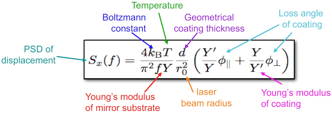
B.1 Amorphous Oxides
Empirical results for amorphous oxide mirrors deposited by IBS show that the mechanical loss at room temperature is reduced by post-deposition annealing, and that the reduction is greater at higher annealing temperatures [178]. The maximum annealing temperature is limited by crystallization of the film. One approach under investigation is to chemically frustrate crystallization through introduction of an appropriate dopant into the coating to increase the temperature at which crystallization occurs. Another approach is to use the oxides mixing available on the market that do not crystallize and that have high refractive index.
There is also some evidence that low deposition rates correlate with reduced losses. A promising result combining these two approaches, the low rate deposition of Zr:tantala and subsequent high temperature annealing, yielded a film with the 4-fold reduction in mechanical loss at room temperature required for aLIGO+ and AdVirgo+ mirrors, though this result is not fully reproducible. It should also be noted that no measurements of cryogenic losses are available and changes in room temperature losses and cryogenic losses are often anticorrelated, so the effects of this material on cryogenic 2.5G and 3G detectors are not yet clear [179]. Some measurements have begun to support a different approach to suppress crystallization and thus allow higher annealing temperatures, geometrically frustrating crystallization using nano-layers, where each quarter-wave layer consists of alternating layers of two materials with a thickness of several nanometers. Suppression of crystallization has been observed in such titania/silica nanolayers [180]. Concerns such as homogeneity, scattering and interface effects in the nanolayers have not yet been characterized.
Another line of research is the one that is trying to use the crystallization as a way to organize the material to medium range order. The aim is to reduce the TLS density and at the same time to keep the nano-crystals dimensions at a level that are not relevant for the scattering.
Until recently, progress in reducing mechanical losses has been based on empirical studies alone. Recently, there has been progress in theoretical tools to guide the empirical work. Molecular dynamics methods enable calculation of the atomic structures that correspond to the energy spectrum of TLS in amorphous materials. Theoretical results correctly predict empirical data for the temperature dependence (at cryogenic temperatures) of losses in model systems like silica, and the trend in loss vs Ti-doping in tantala [102]. Extension to room-temperature regimes is currently under development. These methods also have suggested dopants whose promise has been borne out experimentally, e.g. Zr in tantala. Closely related are experimental methods to determine atomic structure in amorphous films via electron or X-ray diffraction techniques [181, 182, 183]. A “virtuous circle” of theoretical modeling, atomic structure characterization, and macroscopic property measurements (in particular mechanical loss) has reached the stage where the methods mutually reinforce and speed developments in the respective methods.
A theoretical concept that has emerged is that of an ultra-stable glass, i.e. one that has an atomic structure of low internal energy with greatly reduced density of TLS, which is inaccessible to conventional annealing processes on realistic time scales, but can be reached through vapor deposition [184]. According to this picture, deposition at elevated temperatures (to increase surface mobility) and at low rates (to give longer times for surface atoms to explore the energy landscape) should lower the density of TLS. The first empirical example of such an ultra-stable inorganic material, elevated temperature deposition of amorphous silicon with two-order-of-magnitude reduction in cryogenic mechanical losses compared to room-temperature deposition, indicates the physical reality of the concept [185]. This result both shows that a-Si is a promising material for long-wavelength mirrors (though unacceptable levels of optical absorption, discussed below, remain an issue), and motivates the search for ultra-stable amorphous oxides suitable for 1 m wavelength operation. Recent results for amorphous alumina show lower cryogenic losses even after annealing than in room-temperature deposited films, which appears, subject to further verification, the first example of an ultra-stable amorphous oxide. It is also a promising material for a low-index layer in a cryogenic mirror, since its mechanical loss is almost an order of magnitude lower than silica at cryogenic temperatures. These studies are in an early stage; further work (theoretical and empirical) is necessary to establish whether the ultra-stable glass concept is a route to a low-noise cryogenic mirror.
B.2 Semiconductor Materials
The results for the mechanical loss of amorphous silicon deposited at elevated temperatures show that a mirror consisting of a-Si as a high-index layer together with silica as a low index layer would meet the thermal noise requirements for cryogenic detectors [186]. The issue that remains in this case is the optical loss, which is more than an order of magnitude higher than typical requirements. This absorption is associated with “dangling bonds” in silicon atoms that are three-fold rather than four-fold coordinated. As such, this mechanism is not intrinsic, and depends strongly on deposition conditions and post-deposition processing. For example, low deposition rates, post-deposition annealing and annealing in hydrogen can all reduce the absorption significantly, and are topics of active current research [187]. The absorption cross-section decreases with increasing wavelength, resulting in a strong preference for 2 m vs 1.5 m wavelength operation, and probably eliminating this material for use at 1 m. It is also worth noting that the best results for cryogenic losses in a-Si have been obtained with films fabricated by evaporation rather than sputtering [185]. Verification of these results in sputtered films is important, since meeting optical quality requirements is not practical via evaporative deposition methods.
Silicon nitride is another material widely used in the semiconductor industry with potential for low-noise mirrors. Low-pressure chemical vapor deposition (LPCVD) produces films with adequate mechanical loss that, together with silica low-index layers, could form a mirror that meets thermal noise specifications for ET-LF or Voyager [188]. IBS deposited silicon nitride has been also produced with a 1.8-fold reduction of mechanical losses at room temperature with respect to titania doped tantala [188]. Both processes result in excess optical absorption, which is currently more than order of magnitude too large to meet specifications, but, with further development, silicon nitride, unlike amorphous silicon, has the potential to be used with 1 m wavelength operation. Another potential problem is the high Young’s modulus, which makes the material more suitable for silicon or sapphire than for silica substrates.
B.3 Multi-Material Coatings
In this sense, the problem for semiconductor materials is the converse of that for oxide materials: the mechanical properties are adequate, but the optical absorption is too high. A general approach that can address this problem is the use of multi-material coatings, in which the top layers, where the optical intensity is highest, consist of materials with low optical absorption but too large mechanical loss, while the lower layers consist of materials with low mechanical loss but too large optical absorption [189, 190]. In this way, the limitations of the types of material can be traded off against each other. Examples exist of multi-material coatings based on demonstrated material properties that could meet the requirements of ET-LF; the method is reviewed in [191]. While the additional complexity of depositing such multi-material coatings could pose a fabrication challenge, especially if the optimal deposition method differs for the different materials involved, it remains an important option if simpler material combinations fail to meet requirements.
B.4 Crystalline Coatings
Epitaxially grown coatings consisting of alternating layers of high and low index layers of crystalline materials present an alternative method that avoids the mechanical loss issues associated with TLS in amorphous materials. The best developed of these materials are AlGaAs/GaAs mirrors grown by molecular beam epitaxy (MBE) on GaAs substrates and then transferred by wafer-bonding methods to mirror substrates such as silica, silicon or sapphire [192]. The mechanical and optical losses measured in small cavities with mirrors made in this fashion appear adequate for 2.5G and 3G detectors. As compressional mechanical losses are considerably higher than shear losses, it needs to be clarified whether thermal noise is as low for larger beam diameters, where compressional losses become more important.
The issues with respect to applying these as general solutions for gravitational wave interferometry are related to scaling. One scaling issue is associated with developing the infrastructure necessary for fabrication of 40 cm (or larger) diameter optics: growth of the necessary GaAs crystal substrates, and development of MBE and wafer-bonding tools meeting the optical homogeneity requirements. An order of magnitude estimate of the cost of that effort is $ 25 M [193]. The other issue is related to MBE growth, in which an areal density of discrete defects generally appears. While these defects can be avoided in experiments with small beams by alignment in small cavities, this would not be the case with beam sizes characteristic of full-scale detector configurations. The optical scatter, absorption, and elastic loss associated with these defects are not yet well characterized, nor is their anticipated density known. Samples with several inch diameters are currently being characterized to better understand these issues, which presumably should be clarified before the investment in scaling the tooling is seriously considered. The effects of the electro-optic and piezoelectric sensitivities of these crystalline materials must also be investigated.
A less well-developed approach is the use of GaP/AlGaP crystalline coatings [194]. These have the advantage of being able to be grown directly onto silicon, removing the need for transferring the coating between substrates. Initial measurements of the cryogenic mechanical loss of these coatings appear very promising for use in cryogenic gravitational wave detectors. However, significant work on refining deposition parameters and reducing optical absorption is likely to be required.
B.5 Current Research Programs
There are several current and planned programs devoted to developing low-thermal-noise mirror coatings suitable for enhanced 2G, 2.5G, and 3G detectors. Participants are involved in all aspects of coating research, including various deposition methods, characterization of macroscopic properties at room and cryogenic temperatures, and atomic structure modeling and characterization. The recent incorporation into the project of several groups involved in coating deposition is particularly important, as the costs and time delays associated with commercial deposition of research coatings have been significant impediments to rapid progress. The efforts in the LSC and Virgo are presently somewhat independent although with good information exchange.
B.5.1 LSC
There are approximately ten U.S. university research groups participating in various aspects of coating research. In late 2017, a more coordinated effort and additional funding for these groups were initiated under the Center for Coatings Research (CCR), jointly funded by the Gordon and Betty Moore Foundation and the NSF. Work in the U.S. also importantly includes that in the LIGO Laboratory. These efforts are complemented by groups not formally affiliated with the CCR, notably that by the large optical coating group at U. Montreal. Other major LSC coatings research programs are those in GEO (U. Glasgow, U. Strathclyde, U. West of Scotland, U. Hamburg, U. Hannover). The efforts of these groups are coordinated through biweekly telecons of the LSC Optics Working Group. In 2020, the Australian National University commenced re-commissioning of the IBS coating chamber used successfully by the CSIRO for aLIGO optics. This will hopefully provide a large optic coater for the collaboration.
B.5.2 VIRGO
In Europe about ten universities are involved in various aspects of the VIRGO Coatings R&D Project, including new material research, metrology and more recently simulation. The ViSIONs project, supporting six French laboratories, including the LMA and ILM, is focused on studying the relation between the physical properties of sputtered or evaporated materials and the structural and macroscopic properties of the deposited films. LMA is the only facility currently operational that is capable of producing coatings of the size and optical quality required for gravitational-wave interferometers. LMA has already started improving the uniformity of coating deposition in order to meet the challenges of the Advanced+ detectors. The AdVirgo+ project is considering the use of end cavity mirrors of 55 cm diameter. Therefore LMA has developed plans to upgrade their coaters and tools to deal with such increase of diameter and weight.
Appendix C List of Acronyms
1G first generation
2G second generation
2.5G an improved version of the second detector generation with incrementally new technology
3D three dimensional
3G third generation
A+ the upgraded advanced interferometer generation
LIGO A+ upgraded advanced Laser Interferometer Gravitational wave Observatory
AdVirgo advanced Virgo detector
AdVirgo+ upgraded advanced Virgo detector
AEI Albert Einstein Institute
AlGaAs/GaAs Aluminium-Gallium-Arsenide / Gallium Arsenide
aLIGO advanced LIGO
Alphanov Centre Technologique Optique et Lasers, France
ANR Agence nationale de la recherche
ANU Australian National University
AWC Active Wavefront Control
BHD balanced homodyne detector
BNS binary neutron star
CAD computer aided design
CCR Center for Coatings Research, Stanford
CE Cosmic Explorer
CE1 Cosmic Explorer phase 1, using 2G technology
CE2 Cosmic Explorer phase 2
CERN European Centre for Nuclear Research
CLIO cryogenic 100 m prototype interferometer in the Japanese Kamioka mine
CNRS Centre National de la Recherche Scientifique (the French national research centre for scientific research)
CSIRO Commonwealth Scientific and Industrial Research Organisation (an Australian federal government agency responsible for scientific research)
coating thickness
DarkF an optical simulation code in FORTRAN 90
DARM differential arm motion
Fourier components of the displacement of the system
EOM electro optic modulator
ET Einstein Telescope
ET-HF Einstein Telescope high frequency interferometer
ET-LF Einstein Telescope low frequency interferometer
ETM End Test Mass
FC filter cavity
FEA finite element analysis
FFT fast Fourier transform
FI Faraday isolator
Finesse Frequency-domain interferometer simulation with higher-order spatial modes
Fourier components of the force leading to the displacement of the system
FP Fabry-Perot cavity, a linear optical resonator
FPGA field programmable gate array
GaP/AlGaP Gallium Phosphide / Alluminium Gallium Phosphide
GeNS Gentle Nodal Support System
GEO the GEO collaboration
GEO 600 the German/British 600m gravitational wave detector in Germany
GPU graphics processing unit
GR general relativity
GW gravitational waves
GWAC gravitational wave agency correspondents
GWD gravitational wave detector
GWIC gravitational wave international committee
GWINC Gravitational wave interferometer noise calculator
GWADW Gravitational Wave Advanced Detector Workshop
HEPI hydraulic external pre-isolator
Heraeus a German company producing ultra-pure fused silica glass
HPL long = high power laser
IBS ion-beam sputtering
ICRR institute for cosmic research, University Tokyo
IFI input Faraday isolator
IfoCAD 3D ray tracing tool using Gaussian beams
IIT Indian Institute of Technology
ILM nsitut Lumière Materiè
IMC input Mode cleaner
ITM long = Inner Test mass
JLab Jefferson Lab
the Boltzmann constant
KAGRA Japanese underground gravitational wave detector
interferometer arm length
LASTI LIGO advanced system test interferometer at MIT
LIDAR light detection and ranging
LIGO Laser Interferometer Gravitational wave Observatory
LIGO Lab laboratory running the LIGO Project
LMA Laboratoire des Matériaux Avancés
LSC LIGO Scientific Collaboration
LVC LIGO Virgo Collaboration
LZH Laser Zentrum Hannover
MBE Molecular Beam Epitaxy
MCMC Markov-Chain-Monte-Carlo method
MCz magnetically assisted Czochralski
MIMO multiple in, multiple out
MIST Matlab-based fast modal simulation of paraxial optical systems
MIT Massachusetts Institute of Technology
Mitsubishi Japanese company
ML maturity level
MOPA master oscillator power amplifier
NEMO Neutron Star Extreme Matter Observatory, a plan for a high frequency GW detector in a 2G scale facility
neoVAN4S a solid state laser of the German company NEOLASE
NIST National Institute of Standards and Technology
NN Newtonian noise, a gravitational coupling of surrounding mass (especially of moving mass due to seismic waves or infra-sound) to the mirrors
NSF National Science Foundation
Nufern Fibre laser company
OFI Output Faraday isolator
OMC output mode cleaner
the angular frequency
Optickle a general model for the electro-opto-mechanical part of a GW detector
OptoCAD 2D ray tracing tool using Gaussian beams
OSCAR optical FFT code to simulate Fabry Perot cavities with arbitrary mirror profiles
mechanical loss angle
PR Power Recycling
PSL pre-stabilized laser system
QND Quantum Non-Demolition
QRPN quantum radiation pressure noise
R&D research and development
RF radio frequency
RMS root mean square
SA Super Attenuator
SAS Seismic attenuation system
SimPlant virtual interferometer for commissioning
SIS seismic isolation system
SN shot noise
SNR signal to noise ratio
SPI suspension point interferometer
SQL standard quantum limit
SQZ squeezing, a technology to modify quantum noise distribution over the two quadratures of the light field
SR Signal Recycling
SUS suspension system
Temperature
TCS thermal compensation system
TGG Terbium gallium garnet
TLS two level system
UHV Ultra High Vacuum
USA United States of America
UWS University of the West of Scotland
VCR&D long = Virgo Coating R&D collaboration
Virgo Virgo gravitational wave detector
ViSIONs a coating project funded by \acs*ANR
Voyager Voyager, a detector with 3G technology in the 2G infrastructure
laser beam radius
mechanical admittance
References
- [1] B. Abbott et al. (LIGO Scientific Collaboration). LIGO: the Laser Interferometer Gravitational-Wave Observatory. Reports on Progress in Physics, 72(7):076901, 2009.
- [2] F Acernese et al. Status of Virgo. Classical and Quantum Gravity, 25(11):114045 (8pp), 2008.
- [3] The LIGO Scientific Collaboration. Advanced ligo. Classical and Quantum Gravity, 32(7):074001, 2015.
- [4] F. Acernese et al. Advanced Virgo: a second-generation interferometric gravitational wave detector. Class. Quant. Grav., 32(2):024001, 2015.
- [5] M. Zucker. Getting an a+: Enhancing advanced ligo. https://dcc.ligo.org/LIGO-G1601435/public, 2016.
- [6] G. Cagnoli. Advanced virgo + overview. https://dcc.ligo.org/LIGO-G1800472, 2016.
- [7] Rana X Adhikari, coll Nicolas Smith, Aidan Brooks, and \bibinfopersonothers. Ligo voyager upgrade: Design concept. https://dcc.ligo.org/LIGO-T1400226, 2018.
- [8] P. Agrawal K. Ackley, V. B. Adya et al. Neutron star extreme matter observatory: A kilohertz-band gravitational-wave detector in the global network. Publications of the Astronomical Society of Australia (PASA), 2020.
- [9] Einstein Telescope Science Team. Einstein gravitational wave Telescope conceptual design study, 2011.
- [10] B P Abbott, R Abbott, T D Abbott, and \bibinfopersonothers. Exploring the sensitivity of next generation gravitational wave detectors. Classical and Quantum Gravity, 34(4):044001, 2017.
- [11] R X Adhikari, K Arai, A F Brooks, and \bibinfopersonothers. A cryogenic silicon interferometer for gravitational-wave detection. Classical and Quantum Gravity, 37(16):165003, jul 2020.
- [12] Christopher Wipf. Ligo voyager update. https://dcc.ligo.org/LIGO-G1900594, 2019.
- [13] H. B. Callen and T. A. Welton. Irreversibility and Generalized Noise. Phys. Rev., 83:34, 1951.
- [14] R. Kubo. The fluctuation-dissipation theorem. Reports on Progress in Physics, 29:255–284, January 1966.
- [15] William Bernard and Herbert B. Callen. Irreversible thermodynamics of nonlinear processes and noise in driven systems. Rev. Mod. Phys., 31:1017–1044, Oct 1959.
- [16] Charlotte Bond, Daniel Brown, Andreas Freise, and Kenneth A. Strain. Interferometer techniques for gravitational-wave detection. Living Reviews in Relativity, 19(1):3, Feb 2017.
- [17] Anna-Maria A. van Veggel. Quasi-monolithic mirror suspensions in ground-based gravitational-wave detectors: an overview and look to the future. Philosophical Transactions of the Royal Society A: Mathematical, Physical and Engineering Sciences, 376(2120):20170281, 2018.
- [18] L. Barsotti, L. McCuller, M.Evans, and P. Fritsche. The a+ design curve. https://dcc.ligo.org/public/0149/T1800042/005/T1800042-v5.pdf, 2018. LIGO internal technical report, LIGO-T1800042-v5.
- [19] G. Hammond and S. Rowan. Thermal noise, suspensions and new materials. In 2014 IEEE Metrology for Aerospace (MetroAeroSpace), pages 515–520, May 2014.
- [20] Lisa Barsotti, Jan Harms, and Roman Schnabel. Squeezed vacuum states of light for gravitational wave detectors. Reports on Progress in Physics, 82(1):016905, dec 2018.
- [21] Donatella Fiorucci, Jan Harms, Matteo Barsuglia, Irene Fiori, and Federico Paoletti. Impact of infrasound atmospheric noise on gravity detectors used for astrophysical and geophysical applications. Physical Review D, 97, 01 2018.
- [22] LIGO Instrument Science List, :, A. Buikema, and \bibinfopersonothers. Sensitivity and performance of the advanced ligo detectors in the third observing run, 2020.
- [23] The Boring Company. https://www.boringcompany.com, 2019.
- [24] Fred Dylla, Rainer Weiss, and Michael Zucker. Proceedings: Nsf workshop on large ultrahigh-vacuum systems for frontier scientific research. https://dcc.ligo.org/LIGO-P1900072/public, 2019.
- [25] Peter R. Saulson. Terrestrial gravitational noise on a gravitational wave antenna. Phys. Rev. D, 30:732–736, Aug 1984.
- [26] Jan Harms. Terrestrial Gravity Fluctuations. Living Reviews in Relativity, 18(3), 2015.
- [27] Scott A. Hughes and Kip S. Thorne. Seismic gravity-gradient noise in interferometric gravitational-wave detectors. Phys. Rev. D, 58:122002, Nov 1998.
- [28] M Beccaria, M Bernardini, S Braccini, and \bibinfopersonothers. Relevance of newtonian seismic noise for the virgo interferometer sensitivity. Classical and Quantum Gravity, 15(11):3339, 1998.
- [29] Teviet Creighton. Tumbleweeds and airborne gravitational noise sources for ligo. Classical and Quantum Gravity, 25(12):125011, 2008.
- [30] Donatella Fiorucci, Jan Harms, Matteo Barsuglia, Irene Fiori, and Federico Paoletti. Impact of infrasound atmospheric noise on gravity detectors used for astrophysical and geophysical applications. Phys. Rev. D, 97:062003, Mar 2018.
- [31] Jan Harms and Stefan Hild. Passive Newtonian noise suppression for gravitational-wave observatories based on shaping of the local topography. Classical and Quantum Gravity, 31(18):185011, 2014.
- [32] G. Cella. Off-Line Subtraction of Seismic Newtonian Noise. In B. Casciaro, D. Fortunato, M. Francaviglia, and A. Masiello, editors, Recent Developments in General Relativity, pages 495–503. Springer Milan, 2000.
- [33] M Coughlin, N Mukund, J Harms, and \bibinfopersonothers. Towards a first design of a Newtonian-noise cancellation system for Advanced LIGO. Classical and Quantum Gravity, 33(24):244001, 2016.
- [34] M.G. Beker, G. Cella, R. DeSalvo, and \bibinfopersonothers. Improving the sensitivity of future GW observatories in the 1 - 10Hz band: Newtonian and seismic noise. General Relativity and Gravitation, 43(2):623–656, 2011.
- [35] J. Harms, J.-P. Ampuero, M. Barsuglia, and \bibinfopersonothers. Transient gravity perturbations induced by earthquake rupture. Geophysical Journal International, 201(3):1416–1425, 2015.
- [36] J. Harms. Transient gravity perturbations from a double-couple in a homogeneous half space. Geophysical Journal International, 2016.
- [37] M G Beker, J F J van den Brand, E Hennes, and D S Rabeling. Towards time domain finite element analysis of gravity gradient noise. Journal of Physics: Conference Series, 228(1):012034, 2010.
- [38] M Coughlin and J Harms. Seismic topographic scattering in the context of GW detector site selection. Classical and Quantum Gravity, 29:075004, 2012.
- [39] Jan Harms and Krishna Venkateswara. Newtonian-noise cancellation in large-scale interferometric GW detectors using seismic tiltmeters. Classical and Quantum Gravity, 33(23):234001, 2016.
- [40] M. W. Coughlin, J. Harms, J. Driggers, and \bibinfopersonothers. Implications of dedicated seismometer measurements on Newtonian-noise cancellation for Advanced LIGO. PRL (accepted Nov. 2018, 2018.
- [41] M Coughlin, J Harms, N Christensen, and \bibinfopersonothers. Wiener filtering with a seismic underground array at the Sanford Underground Research Facility. Classical and Quantum Gravity, 31(21):215003, 2014.
- [42] Michael Coughlin and Jan Harms. Global characterization of seismic noise with broadband seismometers. arXiv, 2012.
- [43] Jan Harms and Brian O’Reilly. Velocity and Attenuation Characterization of the LIGO Site near Livingston, Louisiana. Bulletin of the Seismological Society of America, 101(4):1478–1487, 2011.
- [44] J. Peterson. Observation and modeling of seismic background noise. Open-file report U. S. Geological Survey, 93-322, 1993.
- [45] D J McManus, P W F Forsyth, M J Yap, and \bibinfopersonothers. Mechanical characterisation of the torpedo: a low frequency gravitational force sensor. Classical and Quantum Gravity, 34(13):135002, 2017.
- [46] Tomislav Andric and Jan Harms. Simulations of gravitoelastic correlations for the Sardinian candidate site of the Einstein Telescope. Earth and Space Science Open Archive, page 26, 2020.
- [47] F Matichard, B Lantz, R Mittleman, and \bibinfopersonothers. Seismic isolation of advanced LIGO: Review of strategy, instrumentation and performance. Classical and Quantum Gravity, 32(18):185003, aug 2015.
- [48] Yoichi Aso, Yuta Michimura, Kentaro Somiya, and \bibinfopersonothers. Interferometer design of the KAGRA gravitational wave detector. Phys. Rev. D, 88:043007, Aug 2013.
- [49] A Heptonstall, M A Barton, A S Bell, and \bibinfopersonothers. Enhanced characteristics of fused silica fibers using laser polishing. Classical and Quantum Gravity, 31(10):105006, 2014.
- [50] Chris J Bell, Stuart Reid, James Faller, and \bibinfopersonothers. Experimental results for nulling the effective thermal expansion coefficient of fused silica fibres under a static stress. Classical and Quantum Gravity, 31(6), 2014.
- [51] D Aisa, S Aisa, C Campeggi, and \bibinfopersonothers. The advanced virgo monolithic fused silica suspension. Nuclear Instruments and Methods in Physics Research Section A: Accelerators, Spectrometers, Detectors and Associated Equipment, 824:644–645, 2016.
- [52] K. V. Tokmakov, A. Cumming, J. Hough, and \bibinfopersonothers. A study of the fracture mechanisms in pristine silica fibres utilising high speed imaging techniques. Journal of Non-Crystalline Solids, 358(14):1699–1709, 7 2012.
- [53] P. Amico, L. Bosi, L. Carbone, and \bibinfopersonothers. Monolithic fused silica suspension for the virgo gravitational waves detector. Review of Scientific Instruments, 73(9):3318–3323, 2002.
- [54] Giles Hammond, Stefan Hild, and Matthew Pitkin. Advanced technologies for future ground-based, laser-interferometric gravitational wave detectors. Journal of Modern Optics, 61(sup1):S10–S45, 2014. PMID: 25705087.
- [55] F Travasso and Virgo Collaboration. Status of the monolithic suspensions for advanced virgo. Journal of Physics: Conference Series, 957(1):012012, 2018.
- [56] G D Hammond, A V Cumming, J Hough, and \bibinfopersonothers. Reducing the suspension thermal noise of advanced gravitational wave detectors. Classical and Quantum Gravity, 29(12):124009, 2012.
- [57] R Kumar, D Chen, A Hagiwara, and \bibinfopersonothers. Status of the cryogenic payload system for the kagra detector. Journal of Physics: Conference Series, 716(1):012017, 2016.
- [58] A V Cumming, L Cunningham, G D Hammond, and \bibinfopersonothers. Silicon mirror suspensions for gravitational wave detectors. Classical and Quantum Gravity, 31(2):025017, 2014.
- [59] R Nawrodt, C Schwarz, S Kroker, and \bibinfopersonothers. Investigation of mechanical losses of thin silicon flexures at low temperatures. Classical and Quantum Gravity, 30(11):115008, 2013.
- [60] K. Haughian, D. Chen, L. Cunningham, and \bibinfopersonothers. Mechanical loss of a hydroxide catalysis bond between sapphire substrates and its effect on the sensitivity of future gravitational wave detectors. Phys. Rev. D, 94:082003, Oct 2016.
- [61] M Alshourbagy, P Amico, L Bosi, and \bibinfopersonothers. Measurement of the thermoelastic properties of crystalline si fibres. Classical and Quantum Gravity, 23(8):S277, 2006.
- [62] M. Alshourbagy, P. Amico, L. Bosi, and \bibinfopersonothers. First characterization of silicon crystalline fibers produced with the -pulling technique for future gravitational wave detectors. Review of Scientific Instruments, 77(4):044502, 2006.
- [63] P Amico, L Bosi, L Gammaitoni, and \bibinfopersonothers. Monocrystalline fibres for low thermal noise suspension in advanced gravitational wave detectors. Classical and Quantum Gravity, 21(5):S1009, 2004.
- [64] Mohamed Alshourbagy. Development of single crystal fibers for optical, scintillation and mechnical applications. http://www.infn.it/thesis/PDF/getfile.php?filename=781-Alshourbagy-dottorato.pdf, 2005.
- [65] A Khalaidovski et al. Evaluation of heat extraction through sapphire fibers for the gw observatory kagra. CLASSICAL AND QUANTUM GRAVITY, 31(10):105004, 2014.
- [66] A Dari, F Travasso, H Vocca, and L Gammaitoni. Breaking strength tests on silicon and sapphire bondings for gravitational wave detectors. Classical and Quantum Gravity, 27(4):045010, 2010.
- [67] P Amico, L Bosi, L Carbone, and \bibinfopersonothers. Fused silica suspension for the virgo optics: status and perspectives. Classical and Quantum Gravity, 19(7):1669, 2002.
- [68] Anna-Maria A. van Veggel and Christian J. Killow. Hydroxide catalysis bonding for astronomical instruments. Advanced Optical Technologies, 3(3):293–307, 2014.
- [69] G Hofmann, D Chen, G Bergmann, and \bibinfopersonothers. Indium joints for cryogenic gravitational wave detectors. Classical and Quantum Gravity, 32(24):245013, 2015.
- [70] Peter G Murray, Iain W Martin, Liam Cunningham, and \bibinfopersonothers. Low-temperature mechanical dissipation of thermally evaporated indium film for use in interferometric gravitational wave detectors. Classical and Quantum Gravity, 32(11):115014, 2015.
- [71] F Piergiovanni, M Lorenzini, G Cagnoli, and \bibinfopersonothers. The dynamics of monolithic suspensions for advanced detectors: A 3-segment model. Journal of Physics: Conference Series, 228(1):012017, 2010.
- [72] Borja Sorazu. aligo suspensions characterisation. https://dcc.ligo.org/LIGO-G1700038, 2017.
- [73] Odylio Denys Aguiar. The Past, Present and Future of the Resonant-Mass Gravitational Wave Detectors. Res. Astron. Astrophys., 11:1–42, 2011.
- [74] Kazuhiro Yamamoto, T Uchiyama, S Miyoki, and \bibinfopersonothers. Current status of the clio project. Journal of Physics: Conference Series, 122(1):012002, 2008.
- [75] K Agatsuma et al. Direct measurement of thermal fluctuation of high-q pendulum. PHYSICAL REVIEW LETTERS, 104(4):040602, 2010.
- [76] T Uchiyama et al. Reduction of thermal fluctuations in a cryogenic laser interferometric gravitational wave detector. PHYSICAL REVIEW LETTERS, 108(14):141101, 2012.
- [77] Holger Müller, Sven Herrmann, Claus Braxmaier, Stephan Schiller, and Achim Peters. Modern michelson-morley experiment using cryogenic optical resonators. Phys. Rev. Lett., 91:020401, Jul 2003.
- [78] E. Oelker, R. B. Hutson, C. J. Kennedy, and \bibinfopersonothers. Optical clock intercomparison with 6e-19 precision in one hour. arXiv e-prints, page arXiv:1902.02741, Feb 2019.
- [79] The institute for quantum information and matter (iqim) at caltech. https://iqim.caltech.edu/, 2019.
- [80] Yeram Sarkis Touloukian. Specific heat: metallic elements and alloys. Plenum Press, 1970.
- [81] Eugen Wiens, Qun-Feng Chen, Ingo Ernsting, and \bibinfopersonothers. Silicon single-crystal cryogenic optical resonator. Opt. Lett., 39(11):3242–3245, Jun 2014.
- [82] A. Cavalleri, G. Ciani, R. Dolesi, and \bibinfopersonothers. Increased brownian force noise from molecular impacts in a constrained volume. Phys. Rev. Lett., 103:140601, Sep 2009.
- [83] Minhang Bao and Heng Yang. Squeeze film air damping in mems. Sensors and Actuators A: Physical, 136(1):3 – 27, 2007. 25th Anniversary of Sensors and Actuators A: Physical.
- [84] Paolo Falferi. Testing the intrinsic noise of a coil–magnet actuator for cryogenic gravitational wave interferometers. Classical and Quantum Gravity, 28(14):145005, 2011.
- [85] S. Hild, H. Lück, W. Winkler, and \bibinfopersonothers. Measurement of a low-absorption sample of OH-reduced fused silica. Applied Optics, 45:7269–7272, October 2006.
- [86] Alexandr Ageev, Belkis Cabrera Palmer, Antonio De Felice, Steven D Penn, and Peter R Saulson. Very high quality factor measured in annealed fused silica. Classical and Quantum Gravity, 21(16):3887–3892, jul 2004.
- [87] F. Travasso, P. Amico, L. Bosi, and \bibinfopersonothers. Low-frequency internal friction in silica glass. Europhysics Letters (EPL), 80(5):50008, oct 2007.
- [88] Eiichi Hirose, Dan Bajuk, GariLynn Billingsley, and \bibinfopersonothers. Sapphire mirror for the kagra gravitational wave detector. Phys. Rev. D, 89:062003, Mar 2014.
- [89] E Hirose et al. Characterization of core optics in gravitational-wave detectors: Case study of kagra sapphire mirrors. PHYSICAL REVIEW APPLIED, 14(1):014021, 2020.
- [90] J. Steinlechner, I. W. Martin, A. S. Bell, and \bibinfopersonothers. Silicon-based optical mirror coatings for ultrahigh precision metrology and sensing. Phys. Rev. Lett., 120:263602, Jun 2018.
- [91] Angus S Bell, Jessica Steinlechner, Iain Martin, and \bibinfopersonothers. Anomalous optical surface absorption in nominally pure silicon samples at 1550 nm. Classical and Quantum Gravity, 34, 09 2017.
- [92] Zeno Tornasi et al. Optical properties of silicon for cryogenic interferferometric gravitational wave detectors. https://dcc.ligo.org/LIGO-G1700998.
- [93] S. Rowan, G. Cagnoli, P. Sneddon, and \bibinfopersonothers. Investigation of mechanical loss factors of some candidate materials for the test masses of gravitational wave detectors. Physics Letters A, 265(1):5 – 11, 2000.
- [94] T Uchiyama, T Tomaru, ME Tobar, and \bibinfopersonothers. Mechanical quality factor of a cryogenic sapphire test mass for gravitational wave detectors. Physics Letters A, 261(1):5–11, 1999.
- [95] K Yamamoto et al. Parametric instabilities in the lcgt arm cavity. Journal of Physics: Conference Series, 122(1):012015, 2008.
- [96] T Tomaru et al. Thermal lensing in cryogenic sapphire substrates. Classical and Quantum Gravity, 19(7):2045, 2002.
- [97] Yu Levin. Internal thermal noise in the ligo test masses: A direct approach. Physical Review D, 57(2):659, 1998.
- [98] S. Hild et al. Sensitivity studies for third-generation gravitational wave observatories. Class. Quantum Grav., 28:094013, 2011.
- [99] Vladimir Borisovich Braginsky, VP Mitrofanov, and Vladimir Ivanovich Panov. Systems with small dissipation. University of Chicago Press, 1985.
- [100] HE Bömmel, WP Mason, and AW Warner. Dislocations, relaxations, and anelasticity of crystal quartz. Physical Review, 102(1):64, 1956.
- [101] Rashid Hamdan, Jonathan P Trinastic, and HP Cheng. Molecular dynamics study of the mechanical loss in amorphous pure and doped silica. The Journal of chemical physics, 141(5):054501, 2014.
- [102] Jonathan P Trinastic, Rashid Hamdan, Chris Billman, and Hai-Ping Cheng. Molecular dynamics modeling of mechanical loss in amorphous tantala and titania-doped tantala. Physical Review B, 93(1):014105, 2016.
- [103] Jessica McIver, David Shoemaker, Stefan Ballmer, and \bibinfopersonothers. Global strategies for gravitational wave astronomy. https://dcc.ligo.org/LIGO-P1900028/public, 2018.
- [104] P. Kwee, C. Bogan, K. Danzmann, and \bibinfopersonothers. Stabilized high-power laser system for the gravitational wave detector advanced ligo. Opt. Express, 20(10):10617–10634, May 2012.
- [105] Benno Willke et al. 3G light sources. https://gilsay.physics.gla.ac.uk/dokuwiki/lib/exe/detail.php?id=gwic_3g_rad%3Alight_sources&media=gwic_3g_rad:laser:18laserr_d_for_3g.png, 2019. Accessed: 2019-01-18.
- [106] Benno Willke. personal note following a discussion in 2018 GWADW conference. https://labcit.ligo.caltech.edu/gwadw2018/, 2018.
- [107] LIGO Scientific collabration. Instrument science white paper 2018. https://dcc.ligo.org/LIGO-T1800133/public, 2018.
- [108] Stefan L. Danilishin, Farid Ya. Khalili, and Haixing Miao. Advanced quantum techniques for future gravitational-wave detectors. https://arxiv.org/abs/1903.05223, 2019.
- [109] Carlton M. Caves. Quantum-mechanical noise in an interferometer. Phys. Rev. D, 23:1693–1708, Apr 1981.
- [110] K. A. Strain and B. J. Meers. Experimental demonstration of dual recycling for interferometric gravitational-wave detectors. Phys. Rev. Lett., 66:1391–1394, Mar 1991.
- [111] J. Mizuno, K. A. Strain, P. G. Nelson, and \bibinfopersonothers. Resonant sideband extraction: a new configuration for interferometric gravitational wave detectors. Physics Letters A, 175:273–276, April 1993.
- [112] Osamu Miyakawa, Robert Ward, Rana Adhikari, and \bibinfopersonothers. Measurement of optical response of a detuned resonant sideband extraction gravitational wave detector. Phys. Rev. D, 74:022001, Jul 2006.
- [113] V. B. Braginsky, S. E. Strigin, and S. P. Vyatchanin. Parametric oscillatory instability in Fabry-Perot interferometer. Physics Letters A, 287:331–338, September 2001.
- [114] Matthew Evans et al. Observation of Parametric Instability in Advanced LIGO. Phys. Rev. Lett., 114(16):161102, 2015.
- [115] H. J. Kimble, Y. Levin, A. B. Matsko, K. S. Thorne, and S. P. Vyatchanin. Conversion of conventional gravitational-wave interferometers into quantum nondemolition interferometers by modifying their input and/or output optics. Phys. Rev. D, 65:022002, 2001.
- [116] Patricia Purdue and Yanbei Chen. Practical speed meter designs for quantum nondemolition gravitational-wave interferometers. Phys. Rev. D, 66:122004, Dec 2002.
- [117] Yanbei Chen. Sagnac interferometer as a speed-meter-type, quantum-nondemolition gravitational-wave detector. Phys. Rev. D, 67:122004, Jun 2003.
- [118] V B Braginsky and S P Vyatchanin. Corner reflectors and quantum-non-demolition measurements in gravitational wave antennae. Physics Letters A, 324(5-6):345–360, April 2004.
- [119] A. Buonanno and Y. Chen. Quantum noise in second generation, signal-recycled laser interferometric gravitational-wave detectors. Phys. Rev. D, 64:042006, 2001.
- [120] LIGO Scientific Collaboration, J. Abadie, B. P. Abbott, and \bibinfopersonothers. A gravitational wave observatory operating beyond the quantum shot-noise limit. Nature Physics, 7:962–965, December 2011.
- [121] J. Aasi et al. Enhancing the sensitivity of the LIGO gravitational wave detector by using squeezed states of light. Nature Photon., 7:613–619, 2013.
- [122] M. Evans, L. Barsotti, P. Kwee, J. Harms, and H. Miao. Realistic filter cavities for advanced gravitational wave detectors. Phys. Rev. D, 88:022002, Jul 2013.
- [123] Eleonora Capocasa, Matteo Barsuglia, Jérôme Degallaix, and \bibinfopersonothers. Estimation of losses in a 300 m filter cavity and quantum noise reduction in the kagra gravitational-wave detector. Phys. Rev. D, 93:082004, Apr 2016.
- [124] Peter Fritschel, Matthew Evans, and Valery Frolov. Balanced homodyne readout for quantum limited gravitational wave detectors. Opt. Express, 22(4):4224–4234, Feb 2014.
- [125] M. S. Stefszky, C. M. Mow-Lowry, S. S. Y Chua, and \bibinfopersonothers. Balanced homodyne detection of optical quantum states at audio-band frequencies and below. Classical and Quantum Gravity, 29(14):145015, July 2012.
- [126] Brian Lantz, Stefan Danilishin, Stefan Hild, and \bibinfopersonothers. Lsc instrument science white paper 2018. https://dcc.ligo.org/LIGO-T1800133/public, 2018.
- [127] Chris L. Mueller, Muzammil A. Arain, Giacomo Ciani, and \bibinfopersonothers. The advanced ligo input optics. Review of Scientific Instruments, 87(1):014502, 2016.
- [128] G. Mueller, E. Genin, D. Reitze, P. Saulson, and H. Grote. Advanced Interferometric Gravitational-Wave Detectors: The Input Optics system chapter. World Scientific, 2019.
- [129] A. F. Brooks, R. X. Adhikari, S. Ballmer, L. Barsotti, P. Fulda, A. Perreca . Active wavefront control roadmap, ligo document ligo-t1500188-v5, 2015. LIGO Document LIGO-T1500188-v5.
- [130] The Virgo collaboration. Advanced Virgo technical design report. https://tds.virgo-gw.eu/ql/?c=8940, 2012. Virgo internal document VIR-0128A-12.
- [131] 2m faraday isolators: Electro-optics technology, inc. webpage. https://www.eotech.com/cart/37/free-space-optical-isolators.
- [132] D. V. Martynov et al. Sensitivity of the advanced ligo detectors at the beginning of gravitational wave astronomy. Phys. Rev. D, 93:112004, Jun 2016.
- [133] B. Canuel, E. Genin, M. Mantovani, and \bibinfopersonothers. Sub-nanorad beam pointing monitoring and stabilization system for controlling input beam jitter in gravitational wave interferometers. Appl. Opt., 53(13):2906–2916, May 2014.
- [134] P. Fulda, D. Voss, C. Mueller, and \bibinfopersonothers. Alignment sensing for optical cavities using radio-frequency jitter modulation. Appl. Opt., 56(13):3879–3888, May 2017.
- [135] Andreas Noack, Christina Bogan, and Benno Willke. Higher-order laguerre-gauss modes in (non-) planar four-mirror cavities for future gravitational wave detectors. Opt. Lett., 42(4):751–754, Feb 2017.
- [136] D. B. Tanner, T. Uehara, V. Quetschke, and \bibinfopersonothers. Complex modulation, ligo document ligo-t170470-v41, 2017. LIGO Document LIGO-T170470-v41.
- [137] KAGRA Main Interferometer Working Group . Kagra main interferometer design document, 2012. KAGRA Document T1200913.
- [138] E. Oelker, L. Barsotti, S. Dwyer, D. Sigg, and N. Mavalvala. Squeezed light for advanced gravitational wave detectors and beyond. Opt. Express, 22(17):21106–21121, Aug 2014.
- [139] Eric Genin, Maddalena Mantovani, Gabriel Pillant, and \bibinfopersonothers. Vacuum-compatible low-loss faraday isolator for efficient squeezed-light injection in laser-interferometer-based gravitational-wave detectors. Appl. Opt., 57(32):9705–9713, Nov 2018.
- [140] R. Goetz. A Low Loss Faraday Isolator for Squeezing Injection in Advanced LIGO, and Radio-Frequency Amplitude Modulation. PhD thesis, University of Florida, 2017.
- [141] Eric Oelker, Tomoki Isogai, John Miller, and \bibinfopersonothers. Audio-band frequency-dependent squeezing for gravitational-wave detectors. Phys. Rev. Lett., 116:041102, Jan 2016.
- [142] Guido Mueller, Qi ze Shu, Rana Adhikari, and \bibinfopersonothers. Determination and optimization of mode matching into optical cavities by heterodyne detection. Opt. Lett., 25(4):266–268, Feb 2000.
- [143] Peter Veitch, Aidan Brooks, Won Kim, and \bibinfopersonothers. Hartmann wavefront sensors for advanced ligo. In Conference on Lasers and Electro-Optics, page SW3M.5. Optical Society of America, 2018.
- [144] L van der Schaaf, K Agatsuma, M van Beuzekom, M Gebyehu, and J van den Brand. Advanced virgo phase cameras. Journal of Physics: Conference Series, 718(7):072008, 2016.
- [145] Y. Aso, M. Ando, K. Kawabe, S. Otsuka, and K. Tsubono. Stabilization of a fabry–perot interferometer using a suspension-point interferometer. Physics Letters A, 327(1):1 – 8, 2004.
- [146] B. Caron, L. Derome, R. Flaminio, and \bibinfopersonothers. SIESTA, a time domain, general purpose simulation program for the virgo experiment. Astropart.Phys., 10:369–386, 1999.
- [147] H Yamamoto, B. Bhawal, M Evans, and \bibinfopersonothers. End to end simulation program for gravitational-wave detectors. In Seiji Kawamura and Norikatsu Mio, editors, Graviational Wave Detection II, number 32 in Frontier Science Series. Universal Academy Press, 2000. The software is available at: http://www.ligo.caltech.edu/~e2e/.
- [148] Hiro Yamamoto and Richard Day. SIS, stationary interferometer simulation. https://git.ligo.org/IFOsim/SIS, 2016. Accessed: 2018-11-01.
- [149] Jérôme Degallaix. OSCAR a matlab based optical fft code. Journal of Physics: Conference Series, 228(1):012021, 2010. Code is available at https://www.mathworks.com/matlabcentral/fileexchange/20607-oscar.
- [150] Mikhaël Pichot. DarkF optical simulation code. https://artemis.oca.eu/fr/rechercheartemis/projets/virgo/2-non-categorise/2081-darkf-optical-simulation-code, 2018. Accessed: 2018-11-01.
- [151] J.-Y. Vinet, P. Hello, C. N. Man, and A. Brillet. A high accuracy method for the simulation of non-ideal optical cavities. Journal de Physique I, 2:1287–1303, July 1992.
- [152] Matt Evans. Optickle simulation software. https://github.com/Optickle/Optickle, 2004. Accessed: 2018-05-18.
- [153] Daniel David Brown and Andreas Freise. Finesse. http://www.gwoptics.org/finesse, May 2014.
- [154] A Freise, G Heinzel, H Lück, and \bibinfopersonothers. Frequency-domain interferometer simulation with higher-order spatial modes. Classical and Quantum Gravity, 21(5):S1067, 2004.
- [155] Gabriele Vajente. Fast modal simulation of paraxial optical systems: the MIST open source toolbox. Classical and Quantum Gravity, 30(7):075014, 2013. The software is available at https://sourceforge.net/projects/optics-mist/.
- [156] LIGO Scientific Collaboration. Gravitational wave interferometer noise calculator. https://awiki.ligo-wa.caltech.edu/aLIGO/GWINC, 2015. Accessed: 2018-05-18.
- [157] P.M. Kalmus, R Adhikari, J Betzwieser, and K Arai. Simulated plant approach. https://dcc.ligo.org/LIGO-G1000546/public, 2010.
- [158] Gudrun Wanner, Gerhard Heinzel, Evgenia Kochkina, and \bibinfopersonothers. Methods for simulating the readout of lengths and angles in laser interferometers with gaussian beams. Optics Communications, 285(24):4831 – 4839, 2012.
- [159] Kochkina E, Heinzel G, Wanner G, and \bibinfopersonothers. Simulating and optimizing laser interferometers. In 9th LISA Symposium, volume 467 of ASP Conference Series, page 291, 2013.
- [160] Roland Schilling. OptoCAD: Tracing gaussian TEM00 beams through an optical set-up. http://home.rzg.mpg.de/~ros/optocad.html, 2015. Accessed: 2018-05-18.
- [161] Adam J. Mullavey, Bram J. J. Slagmolen, John Miller, and \bibinfopersonothers. Arm-length stabilisation for interferometric gravitational-wave detectors using frequency-doubled auxiliary lasers. Opt. Express, 20(1):81–89, Jan 2012.
- [162] Rong-Gen Cai and Tao Yang. Estimating cosmological parameters by the simulated data of gravitational waves from the Einstein Telescope. Phys. Rev., D95(4):044024, 2017.
- [163] Bangalore Sathyaprakash. Calibration accuracy. personal communication, 2019.
- [164] Craig Cahillane, Joe Betzwieser, Duncan A. Brown, and \bibinfopersonothers. Calibration uncertainty for advanced ligo’s first and second observing runs. Phys. Rev. D, 96:102001, Nov 2017.
- [165] S. Karki, D. Tuyenbayev, S. Kandhasamy, and \bibinfopersonothers. The advanced ligo photon calibrators. Review of Scientific Instruments, 87(11):114503, 2016.
- [166] Richard Savage. NIST Workshop 2019. https://dcc.ligo.org/cgi-bin/DocDB/DisplayMeeting?conferenceid=1029, 2019.
- [167] L. Matone, P. Raffai, S. Marka, and \bibinfopersonothers. Benefits of artificially generated gravity gradients for interferometric gravitational-wave detectors. Class. Quant. Grav., 24:2217–2230, 2007.
- [168] Yuki Inoue, Sadakazu Haino, Nobuyuki Kanda, and \bibinfopersonothers. Improving the absolute accuracy of the gravitational wave detectors by combining the photon pressure and gravity field calibrators. Phys. Rev., D98(2):022005, 2018.
- [169] D Estevez, B Lieunard, F Marion, and \bibinfopersonothers. First tests of a newtonian calibrator on an interferometric gravitational wave detector. Classical and Quantum Gravity, 35(23):235009, 2018.
- [170] Yuki Inoue, Sadakazu Haino, Nobuyuki Kanda, and \bibinfopersonothers. Improving the absolute accuracy of the gravitational wave detectors by combining the photon pressure and gravity field calibrators. Phys. Rev. D, 98:022005, Jul 2018.
- [171] J R Leong, M Hewitson, H Lück, and \bibinfopersonothers. A new method for the absolute amplitude calibration of GEO 600. Class. Quantum Grav, 29:65001–18, 2012.
- [172] LIGO Scientific Collaboration. Calibration of the advanced ligo detectors for the discovery of the binary black-hole merger gw150914. Phys. Rev. D, 95:062003, Mar 2017.
- [173] Reed Essick and Daniel E. Holz. Calibrating gravitational-wave detectors with GW170817. https://arxiv.org/abs/1902.08076, 2019.
- [174] M. Pitkin, C. Messenger, and L. Wright. Astrophysical calibration of gravitational-wave detectors. Phys. Rev., D93(6):062002, 2016.
- [175] K Yamamoto et al. Measurement of the mechanical loss of a cooled reflective coating for gravitational wave detection. PHYSICAL REVIEW D, 74(2):022002, 2006.
- [176] Eiichi Hirose, Kieran Craig, Hideki Ishitsuka, and \bibinfopersonothers. Mechanical loss of a multilayer tantala/silica coating on a sapphire disk at cryogenic temperatures: Toward the kagra gravitational wave detector. Phys. Rev. D, 90:102004, Nov 2014.
- [177] Gregory M Harry, Andri M Gretarsson, Peter R Saulson, and \bibinfopersonothers. Thermal noise in interferometric gravitational wave detectors due to dielectric optical coatings. Classical and Quantum Gravity, 19(5):897, 2002.
- [178] G Vajente, R Birney, A Ananyeva, and \bibinfopersonothers. Effect of elevated substrate temperature deposition on the mechanical losses in tantala thin film coatings. Classical and Quantum Gravity, 35(7):075001, 2018.
- [179] Iain W Martin, R Bassiri, R Nawrodt, and \bibinfopersonothers. Effect of heat treatment on mechanical dissipation in ta2o5 coatings. Classical and Quantum Gravity, 27(22):225020, 2010.
- [180] Huang-Wei Pan, Shun-Jin Wang, Ling-Chi Kuo, and \bibinfopersonothers. Thickness-dependent crystallization on thermal anneal for titania/silica nm-layer composites deposited by ion beam sputter method. Optics Express, 22(24):29847–29854, 2014.
- [181] R Bassiri, K Evans, KB Borisenko, and \bibinfopersonothers. Correlations between the mechanical loss and atomic structure of amorphous tio2-doped ta2o5 coatings. Acta Materialia, 61(4):1070–1077, 2013.
- [182] Martin J Hart, Riccardo Bassiri, Konstantin B Borisenko, and \bibinfopersonothers. Medium range structural order in amorphous tantala spatially resolved with changes to atomic structure by thermal annealing. Journal of Non-Crystalline Solids, 438:10–17, 2016.
- [183] Badri Shyam, Kevin H Stone, Riccardo Bassiri, and \bibinfopersonothers. Measurement and modeling of short and medium range order in amorphous ta 2 o 5 thin films. Scientific reports, 6:32170, 2016.
- [184] Sadanand Singh, Mark D Ediger, and Juan J De Pablo. Ultrastable glasses from in silico vapour deposition. Nature materials, 12(2):139, 2013.
- [185] Xiao Liu, Daniel R Queen, Thomas H Metcalf, Julie E Karel, and Frances Hellman. Hydrogen-free amorphous silicon with no tunneling states. Physical review letters, 113(2):025503, 2014.
- [186] J Steinlechner, IW Martin, AS Bell, and \bibinfopersonothers. Silicon-based optical mirror coatings for ultrahigh precision metrology and sensing. Physical review letters, 120(26):263602, 2018.
- [187] R Birney, J Steinlechner, Z Tornasi, and \bibinfopersonothers. Amorphous silicon with extremely low absorption: beating thermal noise in gravitational astronomy. Physical review letters, 121(19):191101, 2018.
- [188] Huang-Wei Pan, Ling-Chi Kuo, Lin-An Chang, and \bibinfopersonothers. Silicon nitride and silica quarter-wave stacks for low-thermal-noise mirror coatings. Physical Review D, 98(10):102001, 2018.
- [189] William Yam, Slawek Gras, and Matthew Evans. Multimaterial coatings with reduced thermal noise. Physical Review D, 91(4):042002, 2015.
- [190] Jessica Steinlechner, Iain W Martin, Jim Hough, and \bibinfopersonothers. Thermal noise reduction and absorption optimization via multimaterial coatings. Physical Review D, 91(4):042001, 2015.
- [191] Craig, K., et al. Expanding the Gravitational-Wave Detection Band to Low Frequencies: A Coating Solution for the Cryogenic Einstein Telescope. https://dcc.ligo.org/LIGO-P1800241, 2018.
- [192] Garrett D Cole, Wei Zhang, Michael J Martin, Jun Ye, and Markus Aspelmeyer. Tenfold reduction of brownian noise in high-reflectivity optical coatings. Nature Photonics, 7(8):644, 2013.
- [193] Cole, Garrett. Outlook on Size-Scaling of Substrate-Transferred Crystalline Coatings. https://dcc.ligo.org/LIGO-G1801024, 2018. LIGO Document LIGO-G1801024.
- [194] Angie C Lin, Riccardo Bassiri, Suraya Omar, and \bibinfopersonothers. Epitaxial growth of gap/algap mirrors on si for low thermal noise optical coatings. Optical Materials Express, 5(8):1890–1897, 2015.