An optical elevator for precise delivery of cold atoms using an acousto-optical deflector
Abstract
We implement a simple method for fast and precise delivery of ultracold atoms to a microscopic device, i.e. a Fabry-Perot microcavity. By moving a single beam optical dipole trap in a direction perpendicular to the beam axis with an acousto-optical deflector, we transport up to 1 million atoms within 100 ms over cm. Under these conditions, a transport efficiency above is achieved with only minimal heating. The atomic cloud is accurately positioned within the microcavity and transferred into an intra-cavity optical lattice. With the addition of a secondary guiding beam, we show how residual sloshing motion along the shallow axis of the trap can be minimized.
1 Introduction
The transport of cold neutral atoms has been realized in different experimental contexts. One common motivation is to deliver cold atoms to a “science chamber” benefiting from a lower vacuum pressure and/or better optical access than a “loading chamber” where a magneto-optical trap (MOT) is produced. Transport is also required to enable the interaction of cold atomic samples with in-vacuum microscopic devices such as optical microcavities [1, 2, 3, 4, 5, 6] or micromechanical resonators [7, 8, 9], whose size precludes the direct loading of a MOT in their vicinity.
Different transport schemes have been implemented, which are all based on moving either magnetic of optical traps. Movable magnetic traps have been created by successively activating different pairs of coils placed along a path [10] or by mechanically moving magnetic coils on a rail [11]. Atom chip-based magnetic conveyors have been implemented to transport small ensemble of ultracold atoms with high positioning accuracy [12, 13, 14]. In all these methods, the transport setup reduces the optical access to the atoms along one or multiple directions.
The alternative method is to use optical dipole traps. The transport of a cold atomic cloud has been achieved by moving the waist of a single-beam optical trap along the optical axis. It has been realized by translating a focusing lens [15], by using a pair of focus tunable lenses [16] or more recently by using a Moiré lens [17]. These methods can achieve large transport distances over tens of centimeters, but require either moving or deforming elements or achieve limited transport efficiency. Alternatively, optical conveyor belts have been developed specially in the context of Cavity Quantum Electrodynamics (CQED) experiments [18, 1, 2, 3]. However, they are significantly more complex to implement, requiring costly single frequency high power lasers as well as interferometric phase stabilization, and are limited to few millimeters transport distance except for specific demanding realizations [19, 20, 21]. To conclude this short overview, we note that tight optical tweezers are used for re-arrangement of single atom arrays but the typical displacements are in the 100m range [22, 23, 24, 25, 26].
For experiments requiring the interactions of cold atoms with microscopic devices, several requirements have to be fulfilled. First, the transporting trap should be tight enough for an atomic ensemble to fit inside the target device. Furthermore, the final position of the atomic cloud has to be reproducible with micrometer accuracy. In addition, one would rather avoid moving parts to prevent mechanical vibrations and consequent drifts. Finally, the transport duration between the MOT and the device should be as short as possible to limit atom losses and achieve fast experimental cycle times. For our specific experiment, the endpoint of the transport is located at 12 mm from the starting point where the MOT is obtained. This target endpoint is the optical mode of a fiber Fabry-Perot microcavity (length m, waist m), which is a key element for the generation of multi-particle entangled states by CQED methods [27, 28, 29, 30].
Transporting an atomic cloud over a moderately large distance of cm and, at the same time, position it with micrometer accuracy is challenging. To address this problem, we have developed a new and versatile solution by designing an optical elevator based on a single-beam dipole trap and an acousto-optical deflector (AOD), a device that has been used before but in different contexts [31, 32, 33, 34]. This allows a robust transport with high acceleration, low loss and minimal excitation as the atomic sample is transported along a direction transverse to the beam axis, so a direction of much stronger confinement than along the beam axis. This method is simple to implement, requiring apart from the AOD only a lens and a high-power laser (not necessarily monomode). It allows us to transport a cold atomic cloud over one centimeter with acceleration up to ms-2 and efficiency above 95, and to position it with sub-micrometer accuracy (m). It is also robust as no moving or deforming part is involved.
The paper is organized as follows. In section 2, we describe the qualitative and quantitative features of our transport setup. In section 3, we characterize the setup experimentally and discuss the results. We present in section 4 an upgraded version of the setup with the addition of a guiding beam to reduce the oscillations along the shallow axis of the trap, and conclude by summarizing the results and potential further applications of our method.
2 Implementation of the optical elevator
The transport duration is usually targeted to be as short a possible in order to achieve fast cycle times but different effects limit the minimal achievable duration. The finite trap depth puts an upper limit on the maximal acceleration of the atoms while keeping them trapped. For a given transport distance , this leads to a lower limit of the transport duration . In addition, when the transport duration gets closer to the oscillation period of the trap, non-adiabatic processes induce oscillations of the cloud, heating and atom loss. If a single laser beam is used for trapping, the transport can be performed either perpendicularly or along the beam directions. We briefly analyze the different limits of the transport duration for these two geometries.
For transport along the longitudinal direction [35, 16], the maximal acceleration scales as where is the trap depth, the mass of a Rb atom, and is the Rayleigh range of the dipole trap beam with the waist and the wavelength of the trapping light. We then find . A typical example of longitudinal transport can be found in Ref. [35], where . Non-adiabatic effects are then dominant in the longitudinal geometry and transport schemes based on shortcuts to adiabaticity can be advantageous [36]. For transport along the transverse direction, the maximal acceleration scales as . One then finds . For standard trap parameters, and so the transport is limited by the finite trap depth, enabling a fast and simple transport of cold atoms, that does not required involved shortcuts to adiabaticity nor phase-stabilized standing-waves.
In the following, we implement a transport along the transverse direction by designing an optical elevator based on an acousto-optical deflector (AOD) and a lens. In figure 1, the transport method is presented schematically. The AOD deflects a collimated red-detuned laser beam along the transverse direction: the first diffracted order is used for the optical dipole trap, while all other orders are blocked. An achromatic doublet with a focal distance focuses the collimated laser beam at the center of the science chamber along the -axis. The AOD is placed at the distance behind the lens, hence sweeping the driving radio-frequency (RF) of the AOD produces a translation of the focused beam perpendicular to the optical axis. Atoms are loaded in the dipole trap at the lower position from the magneto-optical trap and transported vertically along the -axis by 12 mm up to the microcavity.
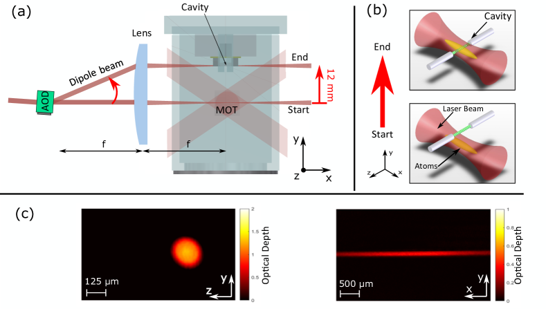
Here we use cold 87Rubidium atoms which have a cooling transition at 780.24 nm. The red-detuned light for the optical dipole trap is provided by a 1070 nm fiber laser with a maximal output power of 50 W [37], which is a linearly polarized multimode laser [38, 39]. The laser output beam which is fiber delivered has an initial beam diameter of 5.0 mm. The AOD has an aperture of 7.5 mm and an efficiency above % over the whole scan angle of 85 mrad [40]. The 2 inches diameter achromat has a focal length mm, which in combination with the scan angle of the AOD allows us to move the dipole trap by up to 14 mm. The lens also sets the trap waist at m. This fulfills two important requirements: it allows the transport beam to overlap with several tens of sites of an intra-cavity optical lattice at a wavelength of nm; on the other hand, it is small enough to fit into the m long cavity without depositing excessive optical power on the fibers.
Due to the tight fit, any misalignment or extended transport duration can cause the high-power laser to damage the micromirrors. We implement a safety system to monitor both the intensity of the dipole trap beam and the frequency of the AOD (representing the transverse position of the beam). It switches off the laser beam if the dipole beam stays close the cavity for too long or when the beam intensity is too large. The radio-frequency (RF) signals used to drive the AOD are provided by a Direct Digital Synthesizer (DDS) [41] controlled by an Arduino microcontroller [42] via serial communication. The DDS is used in the linear sweep mode and the microcontroller performs a dynamical update of the DDS sweeping slope at a rate of up to 20 kHz. This allows the implementation of arbitrary velocity profiles for the transport, where the effect of discretization on the atoms is fully negligible even for transport duration as short as 10 ms [43]. Equivalently, discretization of the profile is negligible if the number of steps is above 100.
3 Transport efficiency and heating
To load the dipole trap, the 1070 nm beam is overlapped with the MOT and a 5 ms molasses cooling is performed before switching off the cooling beams. Approximately atoms are loaded at a power of W, which corresponds to an optical trap depth of K. The longitudinal and transverse trap frequencies are found to be kHz and Hz respectively. For a laser power of 6 W, the temperature of the cloud after loading is about 20K. Residual heating of the atoms is observed on the timescale of 1 s in the static trap. However this will not play a significant role during the transport, as we achieve transport durations in the 100 ms range.
With the RF-control system described in the previous paragraph, an arbitrary velocity profile can be implemented for the transport with a high level of control. We typically use transport ramps which are discretized in 200 time steps. Different velocity profiles have been investigated: the Blackman-Harris function [44, 35], a polynomial of degree 2, a linear function and a constant velocity profile. We observe a clear degradation of the transport if a constant velocity profile is used, while only minor differences exist between all the other profiles. In the following, we use the Blackman-Harris profile (see Appendix), which for a given transport duration leads to a slightly lowest heating of the atoms by about 2K.
To characterize the transport with the optical elevator, the atoms are moved by 10 mm and we measure the transport efficiency and the heating by absorption imaging. Here and are respectively the number of atoms at the initial position and at the final position of the ramp. The temperature increase of the atoms is extracted from and which are the temperature of the atoms at the end and at the start of the transport. All temperatures are measured along the axis by time-of-flight measurement. An hold time of s was applied after the transport to allow for thermalization. In figure 2, the efficiency and the heating are shown as a function of the transport duration for different values of the dipole laser power . If is kept larger than ms, the transport efficiency is above and the heating is kept small for all laser powers. To limit the amount of heat transferred to the microcavity, a laser power of W and a transport duration of ms are considered optimal. With these parameters, atoms are transported with an efficiency of . The cloud temperature is increased by K after transport. The calculated maximal acceleration is ms-2, which is an order of magnitude larger than typical transport schemes along the longitudinal direction. These results show that a fast, robust, and efficient transport can be performed over a wide range of parameters without inducing excessive heating.
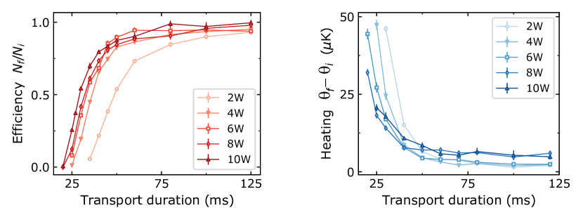
As gets shorter than ms, losses and heating become significant. For the parameters of our transport setup, the minimal transport time due to the finite trap depth is 4.6 times larger than the oscillation period along the transport direction. Therefore, we expect that the minimal duration for an efficient transport is limited by the finite trap depth. By computing the effective potential along the vertical direction in the reference frame of the transport beam moving against gravity for W, we find that the atoms become untrapped when moving faster than 12 ms. This occurs at the time when the acceleration is maximal for a Blackman-Harris velocity profile. For transport duration 12 ms 40 ms, the actual height of the potential barrier is strongly reduced by the acceleration in the moving frame, inducing large atom loss.
Due to the large anisotropy of the trapping potential, we also observe oscillations of the atomic cloud of mm along the longitudinal weak axis of the trap for ms (see Fig. 3). We attribute the excitation of these oscillations to time-dependent thermal aberrations of the AOD and the focusing lens which affect the trapping potential during the transport. These oscillations lead to a less efficient and reproducible loading of the atoms in the cavity mode. We address this issue in the following section.
4 Improved transport and cavity loading
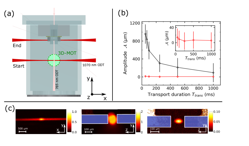
To circumvent the aforementioned longitudinal oscillations, a second red-detuned beam is introduced, orthogonal to the transport beam, creating a crossed dipole trap. This second beam intersects both the center of the fiber cavity and the center of the nm dipole trap at the MOT position, see Figure 3 a. It acts as a guide for the sub-ensemble of atoms at the center of the elongated nm trap. Since the guide beam passes through the microcavity, its heating effect has to be minimized in order to protect the mirror coatings as well as to maintain the cavity stabilization. For this reason, we choose the wavelength of the guide beam to be nm, which is only nm away from the 87Rb D2 line. As the beam waist is m, this allows us to achieve a trap depth of 280K with a reasonably low optical power of 380 mW. This waist size guarantees at the same time low clipping from the cavity mirrors and a small beam divergence along the path between the cavity and the MOT.
To load the atoms in the crossed dipole trap, we proceed as previously described with the additional ramping up of the guide beam power in 25 ms before the molasse phase. With this configuration and a transport duration of 100 ms over 11 mm, the guide beam allows us to increase the atom number in the cavity by . A temperature increase of the atoms by 10K is also observed and deemed acceptable. It can be explained by the adiabatic compression of the cloud as the size of the guide beam is reduced from 80m at the MOT to 50m inside the cavity.
The main advantage of the guide beam is visible in Fig.3b, where the oscillations of the atomic ensemble along the weak axis of the 1070 nm trap are shown for different transport durations. The sloshing amplitude of the atoms in the bare 1070 nm trap is on the order of mm for ms. In the crossed dipole trap, the position of the sub-ensemble is stable within a few tenths of microns, which is small compared to the extension of the cloud itself, enabling the efficient and reproducible loading of atoms inside the cavity.
In our optical microcavity, the atoms are trapped in an intra-cavity standing-wave at 1559 nm, which ensures an equal and maximal coupling of all the atoms with a resonant probing standing wave at 780 nm [45]. To avoid irreversible damages to the cavity mirrors and to be less demanding for the cavity stabilization, we reduce the optical power of both the transport and the guide beams when moving the transport beam closer to the cavity. Starting at 2.5 mm away from the cavity, we reduce exponentially their power to 15 of their initial values, which leads to an approximately isotropic trap with calculated trap frequencies of Hz at the cavity position. We typically end up with atoms in the crossed dipole trap inside the cavity at a temperature of 25K.
The atoms are then transferred adiabatically from the crossed dipole trap to the intra-cavity lattice, by ramping down the transport and guide beam power while increasing the 1559 nm intensity over 20 ms. As the 1559 nm is also used for cavity stabilization, we also have to keep a minimal amount of power inside the cavity corresponding to a trap depth of 10K. In Fig. 3c, we show an absorption image of a cold atoms cloud loaded in a 1 mK deep intracavity lattice after a time-of-flight of 100s. For such a short time, the expansion is negligible compared to the initial size. We load typically around 1600 atoms, and the cloud size is 60m along the cavity axis, corresponding to the loading of about 80 sites with more than 10 atoms per site on average.
5 Conclusion
In this article, a novel scheme for transporting cold atoms into a Fabry-Perot microcavity is presented. It is based on the realization of an optical elevator with an acousto-optical deflector at the focus of a lens. We have presented a new scheme for transporting ultracold atoms that enables a fast transport at high acceleration by moving along the strong axis of the dipole trap while avoiding any mechanical vibration due to the elimination of moving parts. Clouds of atoms are transported over a distance of mm in ms with efficiency above 95 and low residual heating. An additional guide beam, orthogonal to the nm laser, is shown to reduce the effect of atoms sloshing along the weak axis of the dipole trap. This moving crossed dipole elevator has enabled us to deliver the atomic cloud with sub-micrometer accuracy and can therefore be used to precisely position a cold atomic ensemble in or nearby microscopic devices. In our lab, this fast and highly reproducible scheme enables future studies of many-body QED entanglement generation for quantum metrology [46] and quantum simulations [47]. This scheme can be used advantageously in a wide range of applications where cold atomic ensembles must be positioned with high accuracy, in particular near nanodevices such as photonic waveguides and optomechanical resonators.
Acknowledgements
We thank Constance Poulain for careful reading of the manuscript. This project has received funding from: Agence Nationale de la Recherche (ANR) (SAROCEMA project, ANR-14-CE32-0002);
European Research Council (ERC) under the European Union’s Horizon 2020 research and innovation programme Grant agreement No 671133 (EQUEMI project). This work has been supported by Region Ile-de-France in the framework of DIM SIRTEQ. S. Schwartz acknowledges funding from the European Union under the Marie Sklodowska Curie Individual Fellowship Programme H2020-MSCA-IF-2014 (project No. 658253).
Appendix
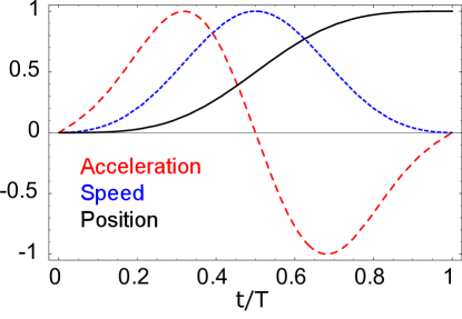
The Blackman-Harris profile of the speed used to transport the atoms over a distance in a time is given by the following equation :
The Blackman-Harris profile describes the velocity of the atoms while they move over a distance D in a time T with the following equation:
| (1) |
In figure 4, the acceleration, velocity and position are shown for .
References
References
- [1] Sauer J A, Fortier K M, Chang M S, Hamley C D and Chapman M S 2004 Phys. Rev. A 69 051804 ISSN 1050-2947, 1094-1622 URL https://link.aps.org/doi/10.1103/PhysRevA.69.051804
- [2] Nußmann S, Hijlkema M, Weber B, Rohde F, Rempe G and Kuhn A 2005 Phys. Rev. Lett. 95 173602 URL https://link.aps.org/doi/10.1103/PhysRevLett.95.173602
- [3] Khudaverdyan M, Alt W, Dotsenko I, Kampschulte T, Lenhard K, Rauschenbeutel A, Reick S, Schörner K, Widera A and Meschede D 2008 New J. Phys. 10 073023 ISSN 1367-2630 URL https://iopscience.iop.org/article/10.1088/1367-2630/aaa634
- [4] Kim M E, Chang T H, Fields B M, Chen C A and Hung C L 2019 Nat Commun 10 1–8 ISSN 2041-1723 URL http://www.nature.com/articles/s41467-019-09635-7
- [5] Béguin J B, Burgers A P, Burgers A P, Luan X, Qin Z, Qin Z, Yu S P, Yu S P and Kimble H J 2020 Optica 7 1–2 ISSN 2334-2536 URL https://www.osapublishing.org/optica/abstract.cfm?uri=optica-7-1-1
- [6] Ðorđević T, Samutpraphoot P, Ocola P L, Bernien H, Grinkemeyer B, Dimitrova I, Vuletić V and Lukin M D 2021 Science 373 1511–1514 URL https://www.science.org/doi/full/10.1126/science.abi9917
- [7] Hunger D, Camerer S, Hänsch T W, König D, Kotthaus J P, Reichel J and Treutlein P 2010 Phys. Rev. Lett. 104 143002 URL https://link.aps.org/doi/10.1103/PhysRevLett.104.143002
- [8] Gierling M, Schneeweiss P, Visanescu G, Federsel P, Häffner M, Kern D P, Judd T E, Günther A and Fortágh J 2011 Nature Nanotech 6 446–451 ISSN 1748-3395 URL http://www.nature.com/articles/nnano.2011.80
- [9] Montoya C, Valencia J, Geraci A A, Eardley M, Moreland J, Hollberg L and Kitching J 2015 Phys. Rev. A 91 063835 URL https://link.aps.org/doi/10.1103/PhysRevA.91.063835
- [10] Greiner M, Bloch I, Hänsch T W and Esslinger T 2001 Phys. Rev. A 63 031401 ISSN 1050-2947, 1094-1622 URL https://link.aps.org/doi/10.1103/PhysRevA.63.031401
- [11] Goldwin J, Inouye S, Olsen M L, Newman B, DePaola B D and Jin D S 2004 Phys. Rev. A 70 021601 ISSN 1050-2947, 1094-1622 URL https://link.aps.org/doi/10.1103/PhysRevA.70.021601
- [12] Hänsel W, Reichel J, Hommelhoff P and Hänsch T W 2001 Phys. Rev. Lett. 86 608–611 ISSN 0031-9007, 1079-7114 URL https://link.aps.org/doi/10.1103/PhysRevLett.86.608
- [13] Long R, Rom T, Hänsel W, Hänsch T W and Reichel J 2005 Eur. Phys. J. D 35 125–133 ISSN 1434-6060, 1434-6079 URL http://www.springerlink.com/index/10.1140/epjd/e2005-00177-6
- [14] Günther A, Kemmler M, Kraft S, Vale C J, Zimmermann C and Fortágh J 2005 Phys. Rev. A 71 063619 URL https://link.aps.org/doi/10.1103/PhysRevA.71.063619
- [15] Gustavson T L, Chikkatur A P, Leanhardt A E, Gorlitz A, Gupta S, Pritchard D E and Ketterle W 2001 Phys. Rev. Lett. 88 020401 ISSN 0031-9007, 1079-7114 (Preprint cond-mat/0108496) URL https://journals.aps.org/prl/abstract/10.1103/PhysRevLett.88.020401
- [16] Léonard J, Lee M, Morales A, Karg T M, Esslinger T and Donner T 2014 New J. Phys. 16 093028 ISSN 1367-2630 URL https://iopscience.iop.org/article/10.1088/1367-2630/16/9/093028/meta
- [17] Unnikrishnan G, Beulenkamp C, Zhang D, Zamarski K P, Landini M and Nägerl H C 2021 Review of Scientific Instruments 92 063205 ISSN 0034-6748, 1089-7623 URL https://aip.scitation.org/doi/10.1063/5.0049320
- [18] Kuhr S, Alt W, Schrader D, Müller M, Gomer V and Meschede D 2001 Science 293 278–280 ISSN 0036-8075, 1095-9203 URL https://science.sciencemag.org/content/293/5528/278
- [19] Schmid S, Thalhammer G, Winkler K, Lang F and Denschlag J H 2006 New J. Phys. 8 159–159 ISSN 1367-2630 URL https://iopscience.iop.org/article/10.1088/1367-2630/8/8/159
- [20] Middelmann T, Falke S, Lisdat C and Sterr U 2012 New J. Phys. 14 073020 ISSN 1367-2630 URL https://doi.org/10.1088/1367-2630/14/7/073020
- [21] Klostermann T, Cabrera C R, von Raven H, Wienand J F, Schweizer C, Bloch I and Aidelsburger M 2021 arXiv:2109.03804 [cond-mat, physics:quant-ph] (Preprint 2109.03804) URL http://arxiv.org/abs/2109.03804
- [22] Beugnon J, Tuchendler C, Marion H, Gaëtan A, Miroshnychenko Y, Sortais Y R P, Lance A M, Jones M P A, Messin G, Browaeys A and Grangier P 2007 Nature Physics 3 696–699 ISSN 1745-2481 URL http://www.nature.com/articles/nphys698
- [23] Lengwenus A, Kruse J, Schlosser M, Tichelmann S and Birkl G 2010 Phys. Rev. Lett. 105 170502 URL https://link.aps.org/doi/10.1103/PhysRevLett.105.170502
- [24] Endres M, Bernien H, Keesling A, Levine H, Anschuetz E R, Krajenbrink A, Senko C, Vuletic V, Greiner M and Lukin M D 2016 Science 354 1024–1027 ISSN 0036-8075, 1095-9203 URL https://www.sciencemag.org/lookup/doi/10.1126/science.aah3752
- [25] Barredo D, de Léséleuc S, Lienhard V, Lahaye T and Browaeys A 2016 Science 354 1021–1023 ISSN 0036-8075, 1095-9203 URL https://www.sciencemag.org/lookup/doi/10.1126/science.aah3778
- [26] Stuart D and Kuhn A 2018 New J. Phys. 20 023013 ISSN 1367-2630 URL https://iopscience.iop.org/article/10.1088/1367-2630/aaa634
- [27] Haas F, Volz J, Gehr R, Reichel J and Esteve J 2014 Science 344 180–183 ISSN 0036-8075, 1095-9203 URL http://www.sciencemag.org/cgi/doi/10.1126/science.1248905
- [28] Barontini G, Hohmann L, Haas F, Esteve J and Reichel J 2015 Science 349 1317–1321 ISSN 0036-8075 URL http://www.sciencemag.org/cgi/doi/10.1126/science.aaa0754
- [29] McConnell R, Zhang H, Hu J, Ćuk S and Vuletić V 2015 Nature 519 439–442 ISSN 1476-4687 URL https://www.nature.com/articles/nature14293
- [30] Welte S, Hacker B, Daiss S, Ritter S and Rempe G 2017 Phys. Rev. Lett. 118 210503 ISSN 0031-9007, 1079-7114 URL http://link.aps.org/doi/10.1103/PhysRevLett.118.210503
- [31] Onofrio R, Durfee D S, Raman C, Köhl M, Kuklewicz C E and Ketterle W 2000 Phys. Rev. Lett. 84 810–813 URL https://link.aps.org/doi/10.1103/PhysRevLett.84.810
- [32] Henderson K, Ryu C, MacCormick C and Boshier M G 2009 New J. Phys. 11 043030 ISSN 1367-2630 URL https://iopscience.iop.org/article/10.1088/1367-2630/11/4/043030
- [33] Rakonjac A, Deb A B, Hoinka S, Hudson D, Sawyer B J and Kjærgaard N 2012 Opt. Lett. 37 1085 ISSN 0146-9592, 1539-4794 URL https://www.osapublishing.org/abstract.cfm?URI=ol-37-6-1085
- [34] Roberts K O, McKellar T, Fekete J, Rakonjac A, Deb A B and Kjærgaard N 2014 Opt. Lett. 39 2012 ISSN 0146-9592, 1539-4794 URL https://www.osapublishing.org/ol/abstract.cfm?uri=ol-39-7-2012
- [35] Couvert A, Kawalec T, Reinaudi G and Guéry-Odelin D 2008 EPL 83 13001 ISSN 0295-5075 URL https://iopscience.iop.org/article/10.1209/0295-5075/83/13001
- [36] Guéry-Odelin D, Ruschhaupt A, Kiely A, Torrontegui E, Martínez-Garaot S and Muga J G 2019 Rev. Mod. Phys. 91 045001 URL https://link.aps.org/doi/10.1103/RevModPhys.91.045001
- [37] IPG photonics, model: YLR-50-LP-Y12
- [38] Lauber T, Küber J, Wille O and Birkl G 2011 Phys. Rev. A 84 043641 URL https://link.aps.org/doi/10.1103/PhysRevA.84.043641
- [39] Hung W, Huang P, Wu F C, Bruvelis M, Xiao H Y, Ekers A and Yu I A 2015 J. Opt. Soc. Am. B 32 B32–B36 ISSN 1520-8540 URL http://www.osapublishing.org/josab/abstract.cfm?uri=josab-32-5-B32
- [40] AA opto electronic, model: DTSX-400-1064
- [41] Analog devices, model: AD9959/PCB evaluation board
- [42] Arduino, model: Due URL https://store.arduino.cc/arduino-due
- [43] Ferri F 2018 Strong coupling between a fiber-cavity mode and a commensurate atomic lattice Ph.D. thesis Ecole Normale Supérieure
- [44] Harris F 1978 Proceedings of the IEEE 66 51–83 ISSN 1558-2256 URL https://ieeexplore.ieee.org/document/1455106
- [45] Garcia S, Ferri F, Reichel J and Long R 2020 Opt. Express, OE 28 15515–15528 ISSN 1094-4087 URL https://www.osapublishing.org/oe/abstract.cfm?uri=oe-28-10-15515
- [46] Gessner M, Smerzi A and Pezzè L 2020 Nature Communications 11 3817 ISSN 2041-1723 URL http://www.nature.com/articles/s41467-020-17471-3
- [47] Davis E J, Bentsen G, Homeier L, Li T and Schleier-Smith M H 2019 Phys. Rev. Lett. 122 010405 ISSN 0031-9007, 1079-7114 URL https://link.aps.org/doi/10.1103/PhysRevLett.122.010405