Quantum crosstalk analysis for simultaneous gate operations on superconducting qubits
Abstract
Maintaining or even improving gate performance with growing numbers of parallel controlled qubits is a vital requirement for fault-tolerant quantum computing. For superconducting quantum processors, though isolated one- or two-qubit gates have been demonstrated with high fidelity, implementing these gates in parallel commonly shows worse performance. Generally, this degradation is attributed to various crosstalks between qubits, such as quantum crosstalk due to residual inter-qubit coupling. An understanding of the exact nature of these crosstalks is critical to figuring out respective mitigation schemes and improved qubit architecture designs with low crosstalk. Here we give a theoretical analysis of quantum crosstalk impact on simultaneous gate operations in a qubit architecture, where fixed-frequency transmon qubits are coupled via a tunable bus, and sub-100-ns controlled-Z (CZ) gates can be realized by applying a baseband flux pulse on the bus. Our analysis shows that for microwave-driven single-qubit gates, the dressing from the qubit-qubit coupling can cause non-negligible cross-driving errors when qubits operate near frequency collision regions. During CZ gate operations, although unwanted nearest-neighbor interactions are nominally turned off, sub- parasitic next-nearest-neighbor interactions involving spectator qubits can still exist, causing considerable leakage or control error when one operates qubit systems around these parasitic resonance points. To ensure high-fidelity simultaneous operations, there could raise a request to figure out a better way to balance the gate error from target qubit systems themselves and the error from non-participating spectator qubits. Overall, our analysis suggests that towards useful quantum processors, the qubit architecture should be examined carefully in the context of high-fidelity simultaneous gate operations in a scalable qubit lattice.
I Introduction
In pursuit of a useful quantum processor, the quality of qubits (e.g., qubit coherence time and fidelity of gate operations), and the number of qubits are two of the most important figures of merit. Nonetheless, in the practical implementation of quantum processors, an outstanding challenge is how to maintain or even improve gate performance with growing numbers of parallel controlled qubits Martinis2015 . For quantum processors built with superconducting qubits, isolated single-qubit gates with gate error below Kjaergaard2020 ; Chen2016 ; McKay2017 ; Somoroff2021 and two-qubit gates with gate error approaching Kjaergaard2020 ; Barends2019 ; Rol2019 ; Sung2021 ; Xu2020 ; Mitchell2021 ; Wei2021 ; Sete2021 ; Ficheux2021 have been demonstrated in various qubit architectures Kjaergaard2020 . However, in multi-qubit systems, implementing gate operations in parallel has commonly shown worse gate performance, especially for simultaneous two-qubit gate operations applied to nearby qubits, where gate errors are typically increased by Chow2015 ; Arute2019 ; Zhu2021 ; Zhang2021 ; Zajac2021 . Generally, the performance degradation is caused by the crosstalk effect Arute2019 ; Sarovar2020 that breaks the textbook assumption on quantum computing, i.e., gate operations are implemented spatial locally and independently (for a high-level and hardware-agnostic definition of crosstalk, we refer the reader to Ref. Sarovar2020 for details). Moreover, this crosstalk effect can cause not just increased gate errors but even a variety of correlated and nonlocal errors which are particularly harmful to the realization of fault-tolerant quantum computing Fowler2012 . Thus, mitigating the crosstalk effect is critical to improving gate performance in superconducting quantum processors and achieving the long-term goal of fault-tolerant quantum computing.
Recently, various studies on the detection, characterization, and mitigation of crosstalk have been published Sarovar2020 ; Gambetta2012 ; Rudinger2019 ; Huang2020 ; Niu2021 ; Ash-Saki2021 ; Rudinger2021 ; Sung2021 ; Barends2014 ; Abrams2019 ; Dai2021 ; Takita2016 ; Takita2016b ; McKay2019 ; Sundaresan2020 ; Zajac2021 ; Winick2021 ; Deng2021 ; Tripathi2021 ; Murali2020 ; Ding2020 ; Smith2021 . From a high-level and hardware-agnostic perspective, several schemes have been proposed for detecting and characterizing crosstalk in multi-qubit systems Sarovar2020 ; Gambetta2012 ; Rudinger2019 ; Huang2020 ; Niu2021 ; Ash-Saki2021 ; Rudinger2021 . Meanwhile, by taking software strategies, various mitigation schemes have also been proposed, such as, at the qubit- or gate-level, one first characterizes the crosstalk and then actively cancels it with compensated pulses Sung2021 ; Barends2014 ; Abrams2019 ; Dai2021 ; Takita2016 ; Takita2016b ; McKay2019 ; Sundaresan2020 ; Zajac2021 or optimal control pulses Winick2021 ; Deng2021 ; Tripathi2021 , and at the quantum circuit level, one takes better crosstalk-aware compilation schemes and instruction scheduling schemes for implementing quantum algorithms Murali2020 ; Ding2020 ; Smith2021 . However, these detection and characterization schemes cannot in general directly clarify the exact nature of crosstalk, and these software approaches for mitigating crosstalk commonly require complex control and characterization, thus placing heavy resource burdens on the control system and limiting their feasibility for large-scale quantum computing. Given these considerations, besides taking high-level software strategies, it is highly desirable to further understand crosstalk and figure out how to mitigate crosstalk from a hardware perspective.
Crosstalk that appears in multi-qubit superconducting quantum processors is commonly very architecture-dependent. For example, in qubit architectures with fixed coupling and fixed-frequency qubits Chow2015 , the dominated crosstalk is associated with microwave crosstalk and residual inter-qubit coupling Gambetta2012 ; Mitchell2021 ; Wei2021 , whereas in qubit architectures with frequency-tunable qubits or tunable coupling Barends2014 ; Chen2014 ; Yan2018 , the flux crosstalk is considered as more involved Barends2014 ; Abrams2019 . Despite its architecture-dependent multiformity, from the hardware perspective, crosstalk can be categorized into two types according to its physical origination Patterson2019 . One is the classical crosstalk associated with unintended classical electromagnetic couplings, such as DC or AC flux crosstalk Abrams2019 ; Dai2021 and microwave crosstalk Sung2021 ; Mitchell2021 ; Wei2021 . The other one is quantum crosstalk resulting from inter-qubit couplings, such as residual nearest-neighbor (N.N.) coupling Barends2014 ; Wei2021 and next-nearest-neighbor (N.N.N.) coupling Barends2014 ; Yan2018 ; Zhao2020b . An understanding of the exact nature of crosstalk or separating error contributions from different crosstalks is an urgent need for figuring out respective mitigation schemes and for obtaining improved qubit architecture designs with low crosstalk. Although several works have previously examined various quantum crosstalk effects, such as crosstalk for single-qubit gates Gambetta2012 ; Mundada2019 ; Li2020 , two-qubit gates Wei2021 ; Sundaresan2020 ; Mundada2019 ; Ku2020 ; Zhao2020 ; Xu2021 ; Kandala2020 ; Zhao2021 ; Finck2021 ; Noguchi2020 ; Mitchell2021 ; Petrescu2021 ; Leroux2021 ; Li2020 , and spectator-qubit induced crosstalk in multi-qubit systems Takita2016 ; Takita2016b ; McKay2019 ; Sundaresan2020 ; Krinner2020 ; Malekakhlagh2020 ; Cai2021 , they are restricted mainly to isolated two-qubit gates. Crosstalk analysis in the context of simultaneous gate operations on a multi-qubit lattice could provide more physical insight into the nature of the crosstalk effect Zajac2021 ; Chu2021 on practically implemented quantum processors Arute2019 ; Zhu2021 .
In this work, we give a theoretical analysis of quantum crosstalk impact on simultaneous gate operations in a qubit architecture with tunable coupling, as sketched in Fig. 1, where fixed-frequency transmon qubits Koch2007 are coupled via a tunable bus McKay2016 . To do so, we first give detailed descriptions of the proposed qubit architecture, especially focusing on the tunable coupling enabled by the tunable bus, gate operations, and the scalability of the architecture. We then turn to illustrate the quantum crosstalk effect on simultaneous gate operations in this qubit architecture. We consider two typical gate operations, i.e., single-qubit X gate and two-qubit CZ gate:
(i) For simultaneous single-qubit X gate operations, the dressing from the qubit-qubit coupling can induce substantial quantum crosstalk, i.e., cross-driving effect, and the associated crosstalk strength is comparable with that of classical microwave (see Fig. 4). Focusing on the nearest-neighbor qubit pairs, we show that when qubit systems approach the frequency-collision region, the cross-driving effect can make gate performance worse by almost an order of magnitude (see Fig. 6). This suggests that to ensure high-fidelity single-qubit addressing, this dressing-induced cross-driving effect should be considered as a serious contender of the error sources.
(ii) For simultaneous CZ gate operations, we show that due to the quantum crosstalk, the performance of simultaneous CZ gate operations can be almost an order of magnitude worse than that of the isolated case (see Fig. 8). We further illustrate the exact nature of these quantum crosstalks, i.e., residual N.N.N. interactions with small coupling strength, and argue that although unwanted N.N. interactions are nominally turned off, sub- parasitic N.N.N. interactions involving spectator qubits (enabled by high-order processes) can still exist. To mitigate their impact on simultaneous two-qubit gate operations, we show that engineering system parameters (e.g., pushing these parasitic N.N.N. interaction points away from the system working point) (see Fig. 10) or implementing short-time gate operations (see Fig. 12) could mitigate the quantum crosstalk impact on simultaneous gate operations. However, on the contrary, gate operations with a slower speed can, in general, suppress unwanted interactions within target qubit systems. Hence, we argue that for high-fidelity simultaneous gate operations, this could give rise to a trade-off between the error resulting from target qubit systems themselves and the error from non-participating spectator qubits (see Fig. 12). More strikingly, this trade-off suggests that even without the consideration of qubit decoherence error, gate operations with slower speeds do not always show better performance.
Overall, the analysis presented in this work shows that isolated gate performance, especially, obtained with all non-participating spectator qubits in their ground states, cannot capture its true performance for the realistic situation in which gates are implemented simultaneously. Towards a functional quantum processor, the performance of quantum processors should be examined carefully in the context of simultaneous gate operations. The analysis can improve our understanding of the exact nature of quantum crosstalk and its impact on simultaneous gate operations, thus may also pave the way for figuring out crosstalk mitigation schemes and qubit architecture designs with low crosstalk. Additionally, the result of this analysis also suggests that the proposed qubit architecture may be a promising architecture towards a large-scale superconducting quantum processor with low crosstalk.
This paper is organized as follows. In Sec. II, we introduce our qubit architecture and give a detailed description of the gate operation in this qubit architecture. In Sec. III, we numerically study the performance of simultaneous gate operations (i.e., simultaneous single-qubit and two-qubit gate operations) in the qubit architecture introduced in Sec. II, analyze the leading error source (i.e., quantum crosstalk) of the added error for the parallel implemented gate operations, and show how to mitigate quantum crosstalk impact on gate operations. In Sec. IV, we give conclusions of our investigation.
II fixed-frequency qubit architectures with tunable buses
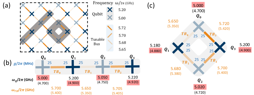
In this section, we propose a qubit architecture comprising fixed-frequency transmon qubits coupled via a tunable bus, as shown in Fig. 1(b). We first focus specifically on this single building block and show how qubit-bus coupling can enable a high-contrast interaction. Therefore, high fidelity single-qubit gates can be achieved with suppression of crosstalk, and a sub-100-ns CZ gate can be realized when we switch on the interaction between qubits. Then, we consider scaling up this building block to scalable two-dimensional (2D) qubit grids.
II.1 System Hamiltonian and tunable ZZ coupling
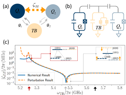
Here, we consider a system of two transmon qubits depicted in Fig. 1(b), where two transmon qubits are coupled through a tunable bus (a third ancilla frequency-tunable transmon qubit). The full system can be modeled by a chain of three weakly anharmonic oscillators Koch2007 with nearest-neighboring coupling, and can be described by (hereafter , notation represents states of the full system, and when restricted to the qubit-subspace, notation is used),
| (1) |
where the subscript labels th oscillator with anharmonicity and frequency , is the associated annihilation (creation) operator, and () denotes the strength of the coupling between qubit and the tunable bus. The qubit-bus coupling can mediate an effective coupling between qubits, which is defined as
| (2) |
where denotes eigenenergy of system associated with dressed eigenstate , which is adiabatically connected to the bare state . According to the fourth-order perturbation theory Krishnan1978 , this effective coupling can be approximated as DiCarlo2009 ; Mundada2019 ; Zhao2020
| (3) |
where , and denote the qubit-bus detuning and qubit-qubit detuning, respectively. In the above expression for coupling strength, the first two terms result from the interaction , and the final one contributes from interaction Zhao2021 ; Jin2021 .
We first consider how to suppress coupling at the system idle point, where single-qubit gates can be implemented with suppression of crosstalk. From Eq. (3), one can find that -free point, i.e., , is independent of the qubit-bus coupling strengths. Assuming and considering , the -free point is at , where the qubit-bus detuning has a magnitude similar to that of qubit anharmonicity Goerz2017 . For transmon qubits with a typical anharmonicity of and operated in the dispersive regime (i.e., ), this means that to suppress residual interaction, the qubit-bus coupling strength should take a value far less than that of the conventional qubit-bus coupling, the strength of which is typically McKay2016 ; Jin2021 . Note here that although qubit systems can in principle operate in the non-dispersive regime (i.e., ), single qubit addressing and eliminating unwanted parasitic interactions, such as N.N.N. coupling, may become highly nontrivial Goerz2017 .
Thus, below, we consider that the qubit-bus coupling strength takes the value , which is similar to the qubit-qubit coupling strength in the conventional qubit architecture with fixed direct coupling Barends2014 . In this way, at the idle point, where the qubit system operates in the dispersive regime, both the qubit addressing error and unwanted parasitic interaction could be suppressed heavily. However, one may doubt that how this rather small qubit-bus coupling can enable a bus-mediated inter-qubit interaction with adequate strength for implementing a successful two-qubit gate. Figure 1(c) shows the coupling strength versus bus frequency with qubit frequency , anharmonicity . The observation is that the destructive interference of coupling contributions from interactions (see Fig. 1(c), the inset outlined with red line) gives rise to a -free point at frequency , where the qubit-bus detuning is comparable to the qubit anharmonicity. This confirms the perturbational analysis given above. When biasing the bus at frequency , there exists a coupling with a strength of , which is adequate and suitable for implementing a sub-100-ns CZ gate. This interaction mainly results from the resonance interaction (see Fig. 1(c), the inset outlined with grey line) at the working point , where denotes the mean qubit frequency.
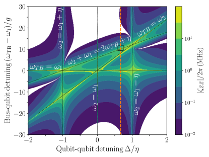
In addition, by fixing ’s frequency at , Figure 2 shows the coupling strength (data points with ZZ coupling strengths below 10 are removed) as a function of qubit-qubit detuning and bus-qubit detuning. One can find that suppression of coupling can be achieved in several parameter zones, such as the straddling regime (i.e., qubit-qubit detuning ) Mundada2019 ; Goerz2017 , and out of the straddling regime with one qubit above and one qubit below the bus in frequency. Moreover, contrary to the conventional qubit-bus system Mundada2019 , one can find that for systems operated out of the straddling regime with qubits below or above the bus in frequency, interaction can still be heavily suppressed. This is to be expected, because in the present qubit system, the qubit-bus coupling is far smaller than that of the conventional case.
II.2 Gate operation
The above illustration shows that the proposed qubit architecture is promising to achieve high-contrast interactions in several different parameter regions. Such flexibility in the choice of parameters can potentially be used to explore various possible advantages for implementing a scalable quantum processor. In the following discussion, we focus specifically on the straddling regime, i.e., .
II.2.1 single-qubit gate
As usual, the -free point is chosen as the system idle point, thus single-qubit gates can be implemented without the detrimental effect from residual interaction. However, we note that for microwave-activated single-qubit gates, while residual coupling is eliminated, there can exist another error source, i.e, cross-driving error. The cross-driving error describes a phenomenon that microwave driving applied to one qubit can cause unintended driving on the others Gambetta2012 ; Patterson2019 . This can be due to classical microwave crosstalk or qubit state dressing (resulting from inter-qubit coupling) induced quantum crosstalk. Here, we restrict ourselves to the last case. Unlike the cross-driving effect resulting from classical microwave crosstalk, the qubit-dressing induced one can create a non-local coherent error on coupled qubits. The exact nature of this cross-driving effect is essentially the same as the cross-resonance (CR) interaction Paraoanu2016 ; Rigetti2010 ; Gambetta2012 , and CR interaction can be seen as a special cross-driving effect, where one intends to maximize the ”non-local coherent error”, thereby, enabling the implementation of a two-qubit gate, i.e., CR gate.
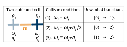
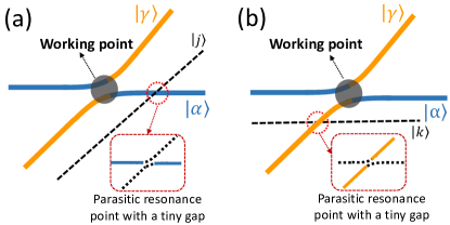
Similar to the classical microwave crosstalk, when we focus on an individual qubit, the dressing-induced cross-driving can excite qubits, causing unintended single-qubit rotation or leakage out of the qubit-subspace. This can result in a substantially large gate error, especially when considering the qubit system operated near the frequency collision regions Malekakhlagh2020 ; Brink2018 . As shown in Fig. 3, there are three main types of frequency collisions: (Type-1) when the frequencies of two coupled qubits are close to the on-resonance condition, the cross-driving between qubits can cause transition within computational subspace, leading to unintended single-qubit rotations; when one qubit’s frequency is nearly on-resonance with the frequency of two-photon transition (Type-2) or high-level transitions (Type-3) of others, the cross-driving can result in population leakage out of qubit-subspace.
For illustration purposes, here we consider a microwave driving with a constant amplitude applied to in the two-qubit system described by Hamiltonian in Eq. (1), intending to implement a single-qubit gate on . The driven Hamiltonian can be described by
| (4) |
with , where denotes the driving amplitude, and is the driving frequency. Similar to the CR interaction, the cross-driving from to is dependent on the state of . By diagonalizing the undriven system Hamiltonian (at the idle point) in Eq. (1), one can obtain the dressed eigenstate . Then, rewriting the driven Hamiltonian Eq. (3) in terms of the dressed eigenstate, one can obtain strength of the cross-driving from to (similar analysis can also be applied to the cross-driving from to ). For example, the strength of the cross-driving from to can be approximated as
| (5) |
where and denote the cross-driving applied to ’s transitions for in the ground and excited states, respectivelyMagesan2020 , and denotes the effective bus-mediated exchange coupling, which can be approximated as .
Similar to the characterization of classical microwave crosstalk, we can define the crosstalk strength of this dressing-induced cross-driving as . Moreover, to quantify the cross-driving induced gate error, here we also introduce the worst-case population error (since off-resonance driving can cause incomplete Rabi oscillation, here we choose the maximum population amplitude as an indicator of the gate error and set ) defined as
| (6) |
where denotes the detuning between the cross-driving frequency and qubit’s transition frequencies between different energy levels.
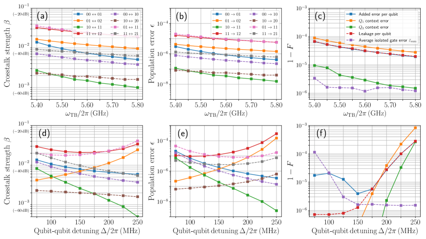
To ensure high-fidelity single-qubit gates, the cross-driving effect should be minimized. From the expression given in Eq. (LABEL:eq5), this can be achieved by reducing exchange coupling and avoiding the qubit frequency collisions shown in Fig. 3. Figures 4(a) and 4(b) show the crosstalk strength between and , and the cross-driving induced population error versus bus frequency. One can find that both the crosstalk strength and the population error are indeed decreased as we increase the bus frequency. In Figs. 4(d) and 4(e), we also show the crosstalk strength and the population error versus qubit-qubit detuning . We find that the crosstalk strength itself is dependent on the detuning , and it is also highly asymmetric (also see Fig. 4(a)). For example, for qubits with lower frequency, i.e., , the cross-driving from (with a higher qubit frequency) to becomes notable when is in the excited state (e.g., ). Meanwhile, the crosstalk from to especially tends to give leakage out of qubit subspace (e.g., and ). Nevertheless, as shown in Fig. 4(e), on the whole, the cross-driving impact on gate fidelity can still be captured by the frequency collision analysis:
(i) For coupled qubits with small qubit-qubit detuning, the system approaches Type-1 frequency collision, thus the dominated error from cross-driving is unintended single-qubit rotations, whereas the leakage error is suppressed.
(ii) When qubit-qubit detuning approaches the anharmonicity of qubits, i.e., the Type-3 frequency collision, the cross-driving induced leakage error is dominated and unintended rotation is greatly reduced. This suggests a fundamental trade-off between control error and leakage error.
(iii) The Type-2 frequency collision seems to have less impact on gate performance Kelly2014 . This is reasonable since the Type-2 frequency collision involves a second-order process that tends to be orders of magnitude weaker than that of Type-1 and Type-3.
In the discussion given above, the population error is just a rough estimation of the cross-driving induced gate error Malekakhlagh2021 . In practical implementations of single-qubit gates, rather than using a constant magnitude driving, one commonly uses a shaped pulse, e.g., Derivative Removal by Adiabatic Gate (DRAG) pulse Motzoi2009 ; Chen2016 ; McKay2017 , thus suppressing leakage out of qubit-subspace. In the following discussion, to implement a single qubit gate, we consider using DRAG scheme with a 20-ns cosine-shaped pulse Chen2016 , given as , where , is the gate time, is the peak pulse amplitude (for , ), is a free parameter that is chosen to suppress leakage error (see Appendix A.1 for details on the calibration procedure of X gates) Motzoi2009 ; Chen2016 ; McKay2017 .
To give a more exact characterization of the cross-driving impact on single-qubit gates, we consider the following virtual experiment: (1) First, an isolated single-qubit gate on qubit is tuned up and characterized with the other qubit in its ground state, giving rise to the isolated gate fidelity, i.e., (here the subscript denotes the state bitstring , and for the active target system to which a gate operation is applied, its qubit state is labeled by ) for and for . (2) Then, the same gate is re-characterized with the other qubit in its excited state, giving rise to for and for . (3) Finally, we consider that both gates are implemented simultaneously, characterization of this composite gate, i.e., , gives rise to the gate fidelity . Here, we define () context error () to characterize the cross-driving impact on isolated single-qubit gates, and define added error per qubit for simultaneous single-qubit gate operations.
To quantify the effect of cross-driving on the gate performance, we use the metric of gate fidelity given as (without qubit decoherence) Pedersen2007
| (7) |
where and denote the target gate operation and implemented gate operation, respectively, and represents the system dimension. In Figs. 4(c) and 4(f), we show the fidelity of gate as a function of bus frequency and qubi-qubit detuning, respectively. Similar to the result shown in Figs. 4(b) and 4(e), one can find that reducing exchange coupling indeed suppresses the cross-driving effect on single-qubit gates, and a non-negligible gate error of about (given the state-of-the-art single-qubit gate error approaching Chen2016 ; McKay2017 ) appears when the qubit-qubit detuning approaching Type-1 or Type-3 frequency collision region. To identify the nature of the added error, we also show the added leakage error per qubit Wood2018 . As shown in Fig. 4(f), for qubit-qubit detuning near the Type-3 frequency collision, the leakage error is indeed the dominated error source, accounting for the added error during simultaneous gate operations. Moreover, the context error also coincides with the leakage, this is true since leakage out of qubit-subspace can only occur when the cross-driven qubit is in the excited state. On the contrary, the context error and leakage errors are far less important near the Type-1 frequency collision region, in which the dominated error is the unintended single-qubit rotations, e.g., under- or over-rotation (bit-flip error) and an additional single-qubit phase error (phase error) when one focuses on each individual qubit.
In addition, it is worth mentioning that under our definition of gate characterization, we always assume that the other nearby qubit is in the ground or excited state, thereby, the cross-driving induced flip of nearby qubit states contributes to errors of the isolated single-qubit gate, i.e., leading to leakage error. Therefore, the added error per qubit cannot capture the cross-driving induced single-qubit rotation error. As shown in Fig. 4(f), near the Type-1 frequency collision region, although the added error per qubit is rather small, the averaged isolated single-qubit error is far larger than that for Type-3 frequency region. As we mentioned before, when the qubit system works nearby the Type-1 frequency collision region, the cross-driving effect can lead to unintended single-qubit rotations on one qubit when single-qubit operations are applied to its neighboring qubits. This explains the increase in average gate error when decreasing qubit-qubit detuning. We thus argue that restricted totally to the isolated single-qubit system regardless of nearby qubits states, i.e., tracing out nearby qubits, one can only achieve a nominally high-fidelity single-qubit gate, which cannot account for its practical performance on multi-qubit systems.
Overall, for the present system operated in the straddling regime, the dressing from the qubit-qubit coupling can induce a substantial cross-driving effect, and the associated crosstalk strength (as shown in Figs. 4(c) and 4(d), typically, from to ) is comparable with that of classical microwave crosstalk Patterson2019 ; Huang2021 . For systems with small qubit-qubit detuning (i.e., near the Type-1 frequency collision region), cross-driving favors bit-flip error or phase error, whereas, for large detuning cases (i.e., near the Type-3 frequency collision region), cross-driving tends to cause leakage error. To ensure high-fidelity single-qubit addressing, the bus-qubit detuning should be large enough, thus bus-mediated exchange coupling is suppressed, and the qubit-qubit detuning should also be away from the frequency collision regions, especially for the Type-1 and Type-3 Kelly2014 . Note here that in principle, the direct coupling between qubit and bus can also cause cross-driving from qubit to bus. However, according to Eqs. (LABEL:eq5) and (6), one can find , thus, here, the cross-driving effect on the bus is heavily suppressed by the large qubit-bus detuning. This was checked for the present system and was found to be less important.
II.2.2 two-qubit gate
As demonstrated in Sec. II.1, for the present qubit architecture operated in the straddling regime, a high-contrast control over interaction can be achieved. When tuning the system energy level on-resonance with , i.e., biasing the bus to the working point at , a sub-100-ns CZ gate can be achieved by using diabatic scheme Barends2019 ; Linghu2020 or fast-adiabatic scheme Xu2020 ; Martinis2014 ; Collodo2020 ; Stehlik2021 . In principle, during the idle time, the system (tunable bus) can be biased to the exact -free point. However, as discussed in Sec. II.2.1, to have a high fidelity single-qubit addressing, besides residual crosstalk, the cross-driving effect should also be minimized. Thus, here the system idle point is chosen so that the typical bus frequency is above the qubit in frequency. In this way, the residual coupling can still be suppressed below , as shown in Figs. 1(c) (marked by the black arrow) and 2. Moreover, to avoid the harmful frequency collision in the straddling regime, the qubit-qubit detuning should be located within specific limits, e.g., , thereby, the single-qubit gate error can be pushed below (or even approaches ), as shown in Fig. 4(f).
In the present qubit architecture, to implement a successful two-qubit gate, several practical experimental limitations also need to be considered seriously:
(1) Uncertainty of system parameters due to fabrication. This is one of the most critical issues faced by fixed-frequency qubits. As shown in Fig. 2, both the available -free zone (where the coupling strength is below 10 ), and the available working zone (where resonance interaction gives rise to a coupling with strength about , indicated by black-dashed line labeled by ) in the straddling regime show a promising insensitivity against variation of qubit-qubit detuning and qubit-bus detuning. Thus, the parameter uncertainty issues could be largely fixed by combing this parameter insensitivity and the state-of-the-art fabrication techniques Kreikebaum2020 ; Hertzberg2020 .
(2) Gate error resulting from qubit relaxation and dephasing. Although fixed-frequency transmon qubit itself can have a long coherence time, qubit relaxation rate or dephasing rate can be enhanced through the tunable bus, which is more vulnerable to system noise, especially, flux noise. Moreover, during the CZ gate operation, a baseband flux pulse is commonly applied to the tunable bus, tuning its frequency from the idle point to the working point. Considering the qubit system shown in Fig. 1, at the working point, the qubit-bus detunings are and . We expect that the small qubit-bus detuning at the working point can cause a strong hybrid between qubit and bus (qubit-bus dressing), especially for , thus the qubit relaxation and dephasing through the bus can become greatly serious McKay2016 ; Xu2020 ; Collodo2020 ; Stehlik2021 . For the noise induced dephasing, this can be mitigated by employing a tunable bus, whose maximum frequency point (i.e., flux-insensitive point) is around the idle point. Therefore, at the idle point, the qubit dephasing through the bus is reduced. Moreover, during CZ gate operations, the needed frequency excursion of the bus is smaller than , thereby potentially greatly reducing flux sensitivity of bus and mitigating the effect of flux noise Arute2019 ; Foxen2020 (in principle, this could be further improved by using tunable buses with asymmetric SQUID Hutchings2017 ).
(3) Flux pulse distortion. Flux pulse distortion is a critical problem faced by baseband flux controlled gate operations. The presence of flux pulse distortion can cause a substantial gate error, such as leakage error and gate bleedthrough, during CZ gate operations Barends2014 ; Foxen2020 ; Martinis2014 ; Kelly2014 . Although pulse distortion can be largely corrected, one needs to characterize it at first Barends2014 . Unfortunately, in general, one can not directly characterize this distortion without control and measurement of the system subjected to pulse distortion. In qubit architectures with tunable buses or couplers, the bus or coupler, in general, does not have a dedicated driving line and readout resonator. Still, one can put these back, but it will greatly increase circuit complexity Sung2021 . Commonly, due to the presence of (classical or dressed-induced) microwave crosstalk, the bus or coupler can be addressed through the driveline of nearby qubits. However, the readout of bus or coupler state through the readout resonator of nearby qubits is still a challenge. One possible strategy is that combined with the readout of nearby qubits, full control on the bus could be achieved through the qubit-bus interaction Leek2009 ; Caldwell2018 ; Pechal2020 , then the distortion could be corrected Jerger2019 ; Rol2020 ; Barends2014 . Meanwhile, in the present qubit architecture, the frequency excursion of the bus is small, thereby potentially mitigating the effect of flux setting tails caused by pulse distortion Foxen2020 ; Foxen2019 .
In the present work, we consider that during the CZ gate operation, a fast adiabatic pulse is applied to the tunable bus, tuning its frequency from the idle point () to the working point () and then back. Expressed in terms of Fourier basis functions, the pulse shape is described as Martinis2014
| (8) |
with constraints on the odd coefficients , and control angle , where denotes the strength of resonance interaction , represents the detuning between and , and is the gate time.
II.3 Scaling up to two-dimensional qubit grids
In principle, the above two transmon qubits system can be exploited as building blocks of scalable qubit architectures. An illustration of a 2D qubit lattice, where each transmon qubit is coupled to four nearest neighbors through tunable buses, is shown in Fig. 5(a). In the 2D qubit lattice, the allocation of qubit and bus frequency follows the following rules:
(1) The frequency of the qubit in each row and column belongs to one of the two frequency bands, i.e., a lower frequency band with typical frequency and a higher frequency band with typical frequency , and qubits in the nearby row or column belong to different frequency bands. Thus, typical detuning between N.N. qubits is about , which is adequate to mitigate cross-driving effect at idle point (Sec. II.2) and to implement a sub-100-ns CZ gate, as demonstrated in Sec. II.1. Moreover, to mitigate microwave crosstalk impact on qubit addressing between next-nearest-neighbor qubits Barends2014 ; Kelly2014 at the idle point and suppress N.N.N. coupling between qubits at the idle and the working point, frequency degeneracy in the lower- or higher-frequency band breaks, yielding typical qubit detuning between next-nearest-neighbors of about .
(2) To have a better balance between the requirement for suppressing qubit-qubit residual interaction and to limit the frequency excursion range during CZ gate operations, the bus frequency is typically above of the qubit in the higher frequency band, as shown in Fig. 5(a).
When considering a practical realization of this qubit lattice, frequency uncertainty due to fabrication is the most critical issue, as discussed in Sec.II.2.2. Besides striving to improve qubit device fabrication precision Kreikebaum2020 ; Hertzberg2020 , one could also try to adopt more sparse qubit connections towards large-scale qubit lattice Hertzberg2020 .
III quantum crosstalk analysis for simultaneous gate operations
In this section, we give a quantum crosstalk analysis for simultaneous gate operations on two four-qubit systems shown in Figs. 5(b) and 5(c), where system-specific parameters are also presented. Similar to the discussion in Sec. II.2.1, to characterize the quantum crosstalk effect on gate performance, we use the metric of gate fidelity given in Eq. (7). The isolated gate fidelity is obtained by characterizing each gate operation individually with all other non-participating spectator qubits at their ground states, and the simultaneous gate fidelity is obtained by characterizing the parallel implemented gate operations (see Appendix A for details on the calibration procedure). To have enough sensitivity to the added error caused by quantum crosstalk during simultaneous gate operations, each isolated gate is optimized numerically, giving typically isolated single-qubit gate error at and typical two-qubit CZ gate error at . Note here that we don’t attempt to search for an optimal isolated gate operation with the lowest error, but only for gate operations with enough fidelity, thus enabling an adequate crosstalk sensitivity.
In addition, we note here that in the following discussion, notations and represent states of the four-qubit square and four-qubit chain system, respectively. When confined to qubit subspace, notation is used.
III.1 Simultaneous single-qubit X gate operations
Here, we consider that two 20-ns single-qubit gates are applied simultaneously to the arbitrary qubit-pair of the four-qubit system, i.e., implementing a composite X gate (). All tunable buses are tuned to their idle points, thus residual interaction between qubits is suppressed below . Same as the discussion in Sec. II.2.1, single-qubit gates are realized by using the DRAG scheme with a cosine-shaped pulse.
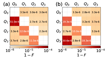
Figures 6(a) and 6(b) show the error matrix of the parallel implemented X gates in the four-qubit chain system shown in Fig. 5(b) and the four-qubit square system shown in Fig. 5(c), respectively. Elements in the upper and lower triangular part of the error matrix denote ideal composite gate error obtained by adding the errors of constituted isolated gates and directly characterizing the parallel implemented gate operations, respectively. We find that almost no additional error is observed for the next-nearest-neighbor qubits, and we thus conclude that the quantum crosstalk between next-nearest-neighbor qubits can be neglected. However, focusing on the nearest-neighbor qubit-pairs, the performance of simultaneous gate operations is almost an order of magnitude worse than that of the isolated case.
The above observations are consistent with the analysis of dressing induced cross-driving effect on the gate performance discussed in Sec. II.2.1. As interactions between next-nearest-neighbor qubits are commonly an order of magnitude weaker than that of nearest-neighbor qubits, the cross-driving effect can be greatly suppressed. On the contrary, the cross-driving effect between nearest-neighbor qubits cannot be ignored, and in general can cause a non-negligible error on the simultaneous gate operations. The error can become even more serious when the nearest-neighbor qubit-pair approaches the frequency collision region. For example, focusing on the qubit-pair in the chain system, the detuning between transition of and transition of (i.e., type-3 frequency collision) takes the smallest value () among all nearby qubits, as marked (in pink shadow) in Fig. 5(b). The closer to the frequency collision region, the more serious the cross-driving error, which can explain that simultaneous gate on qubit-pair has the worst gate performance in the four-qubit chain system. Similar results can also be obtained for the qubit-pair in the square system.
In addition, note that as discussed in Sec. II.2.1, cross-driving induced single-qubit rotation error has been taken into account already for the characterization of the isolated gate performance, and can lead to leakage error since we always assume all the non-participating spectator qubit in their ground states. However, during simultaneous single-qubit gate operations, this rotation error occurs within the two-qubit computational subspace, thus here it does not contribute to the leakage error but the control error for the composite gate operation. The combination of decreased leakage error and increased control error can explain that for the next-nearest-neighbor qubit-pair, whose detuning approaches the Type-1 frequency collision (as discussed in Sec. II.2.1, here the cross-driving effect favors single-qubit rotation error), the ideal composite gate appears to have a little bit larger gate error than that of the simultaneous gate operation, as shown in Fig. 6(a) (we have checked this independency, and find that without consideration of leakage error, this feature indeed disappears).
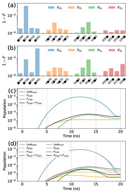
To give a more concrete illustration of the cross-driving impact on the present four-qubit system, Figures 7(a) and 7(b) show the X gate error with the other three spectator qubits in four different state-configurations for the four-qubit chain and square system, respectively. Generally, we find that compared with the isolated gate operation, gate error is increased when a state flip of one nearby qubit occurs. Moreover, qubits in the lower-frequency band show a more prominent decrease in gate performance, such as in the two four-qubit systems. This is to be expected, as detuning between the transition of the qubit in the lower-frequency band and the transition of one in the higher-frequency band, typically, , is smaller than that in the reversed case, typically, . Thus, the cross-driving effect from the low-frequency qubit to the nearby high-frequency qubit is more serious and can result in leakage error for the low-frequency qubit. In Figs. 7(c) and 7(d), we also show the time evolution of state population during with one of ’s nearby qubit in its excited state. For the four-qubit system initialized in , we find that during gate on , the qubit state can be excited from to (see Figs. 7(c) and 7(d), and ), accounting for the dominated leakage error . Similarly, for the four-qubit square system prepared in , the leakage error is mainly resulted from the population leakage of (see Fig. 7(d), dashed line). Overall, the above analysis shows that the dressed induced cross-driving can explain the performance degradation of simultaneous gate operations applied to qubit-pair () in the four-qubit chain system and () in the four-qubit square system.
Before leaving this subsection, we note that although the cross-driving effect can cause almost an order of magnitude worse gate performance in the above illustration, on average the added gate error is about , which is an order of magnitude lower than the state-of-the-art gate performance Chen2016 ; McKay2017 ; Somoroff2021 . However, when qubit systems approach the frequency-collision region or have a larger inter-qubit coupling at the idle point, this cross-driving effect can become a dominant error source for simultaneous single-qubit gate operations. This suggests that the cross-driving effect should be taken seriously into account to design and construct a large multi-qubit lattice.
III.2 Simultaneous two-qubit CZ gate operations
In this subsection, we turn to examine the performance of simultaneous CZ gates in the two four-qubit systems shown in Figs. 5(b) and 5(c). Similar to the analysis of the single-qubit case, we consider that individual CZ gate is tuned up and characterized with the other two nonparticipating qubits in their ground states. During gate operations, except for the bus to which a baseband flux pulse is applied for realizing a CZ gate, the other buses are all biased to their idle points. The CZ gate is implemented by using a fast-adiabatic pulse given in Eq. (8) with three Fourier coefficients , giving rise to totally three free parameters . The other parameters are: gate time , . For reaching a given target error at , the three free parameters are fixed using numerical optimization (see Appendix A.2 for details).
III.2.1 gate performance
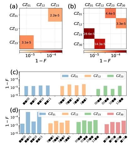
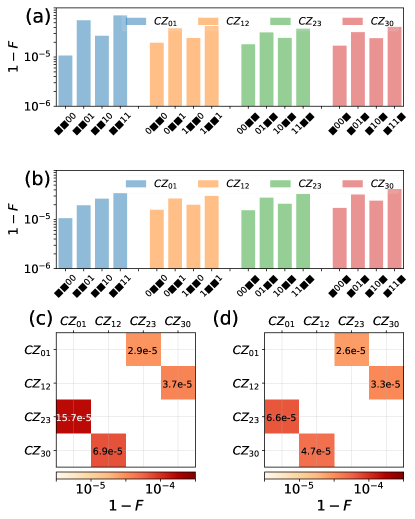
In Figs. 8(a) and 8(b), we show simultaneous CZ gate performance in the four-qubit chain system and four-qubit square system. In the chain system, the added error of simultaneous CZ gates is about , giving an average added error for the individual CZ gate, and in the four-qubit square system, the added error is about and for gate pairs and , respectively, which are about an order of magnitude larger than that of the isolated case. Given the state-of-the-art two-qubit gate performance, although it appears likely that the quantum crosstalk between the gate pair in the chain system is less important, the quantum crosstalk effect on the square system can become a near-term performance limiting factor. Thus, in the following discussion, we can restrict our attention to the square system in which the quantum crosstalk effect is more prominent.
To explore the exact nature of the performance degradation, Figures 8(c) and 8(d) show the CZ gate error with the other two nonparticipating qubits in four different state-configurations for the chain system and square system, respectively. One can find that except for in the square system, gate errors of all the CZ gates show only a weak size dependence on the state of nonparticipating qubits. Typically, here the added error is about . However, in the square system, when is in the excited state, the gate error of is increased by about a factor of 28, giving rise to an added error of .
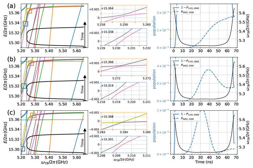
To explain the above striking increase in the gate error, we have examined the time evolution of the square system during with prepared in its excited state. We find that the leakage error, which is caused by the high-order parasitic interaction among , and , can account for the added gate error, as illustrated in Fig. 9(a). From the energy spectrum of the four-qubit square system in the left panel of Fig. 9(a), there exists two avoided crossings resulting from interaction and , which are on either side of the working point at . Thus, when a flux pulse tunes the bus to the working point and then comes back according to the fast-adiabatic pulse given in Eq. (8), the system will first sweep through the avoided crossing () at , and then approaches the avoided crossing () at , as shown in the middle panel of Fig. 9(a). In the right panel of Fig. 9(a), where the time evolution of state population is presented, we find that leakage to mainly occurs when the system approaches the avoided crossing at .
Before giving a more detailed analysis of the leakage error, we note that during an ideal fast adiabatic CZ gate operation, the qubit system should always be in the instantaneous eigenstates of the qubit system. For the system initialized in , the system dynamics should be restricted in the subspace spanned by . In light of this, the above observation can be explained by that as the flux-pulse has a short-time ramp (right panel of Fig. 9(a), black line), and the energy gap of the avoided crossing at is about , the system can thus sweep through it with a negligible leakage to . However, during the main part of the flux-pulse that has a flat shape, the system is almost settled at the working point, where the instantaneous eigenstates is an almost maximal superposition state of and . Moreover, the working point nears the second avoided crossing with a tiny energy gap of at , in which the detuning to the working point is about . Thus, an off-resonance population swap between and occurs, causing significant leakage to . Note here that during the main part of the flux-pulse, the off-resonance population swap between and can also occur due to the avoided crossing at . However, as its detuning to the working point is about and its gap is , the leakage resulting from the off-resonance interaction between to is expected to be far less than that from the off-resonance interaction between and .
The above analysis suggests that although individual gate operations with high gate fidelity can be achieved, implementing the gate operation in parallel can show substantial performance degradation. Moreover, in multiqubit systems, there can exist detrimental high-order parasitic interactions that cannot be captured by only characterizing isolated gate operations with all other nonparticipating qubits in their ground states. On the contrary, characterizing gate operations with other nonparticipating qubits at different state configurations may give further insight into the quantum crosstalk behind the performance degradation of the simultaneous gate operations Krinner2020 .
III.2.2 mitigation of parasitic interaction involving spectator qubits
From the above, the leakage to state is the dominated error source for with in its excited state. Here, we intend to mitigate such errors from the hardware perspective. As the leakage is mainly caused by the existence of the parasitic interaction (i.e., and ) around the working point, here we intend to push them away from the working point. As shown in the left panel of Figs. 9(b) and 9(c), due to the increase of qubit anharmonicities, the energy of state is lowered, thereby, the avoided crossings resulting from the parasitic interactions are far away from the working point. In this way, due to the increased detuning from state , the off-resonance population swap between state and state can be suppressed. Thus, as shown in the right panel of Figs. 9(b) and 9(c), the leakage to is indeed greatly reduced, in line with expectation. Note that this is similar to the incomplete Rabi oscillation resulting from an off-resonance driving, and the population error can be roughly estimated by Eq. (6).
Given the suppression of the leakage error, Fig. 10(a) and Fig. 10(b) show the isolated gate fidelity of with qubit anharmonicity and qubit anharmonicity , respectively. The gate errors of with in its excited state are indeed greatly decreased in both cases. In particular, for the case of , there is no fundamental difference between the gate error of the CZ gate on different qubit-pairs, and gate errors of all pairs show a weak dependence on the state of the nonparticipating qubits. On average, the added error for each operation is suppressed below . Figures 10(c) and 10(d) also present the error matrix of simultaneous CZ gates. We find that compared to the result shown in Fig. 8(b), where , on average the added error of the parallel implemented CZ gates is suppressed twofold for the square system with , and sixfold for .
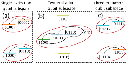
Besides the leakage error, the remaining error could be attributed to the parasitic interactions between next-nearest-neighbor qubits. As shown in Fig. 11, parasitic swap interactions (double-headed arrow) among single-excitation, two-excitation, and three-excitation subspace can exist through high-order processes. Since the typical detuning between next-nearest-neighbor qubits is (see Fig. 5), when a flux pulse tunes the tunable bus from the idle point to the working point, the bus energy levels will push down the qubit energy levels, thus potentially diminishing the detuning between next-nearest-neighbor qubits and leading to population swap between next-nearest-neighbor qubits. Thanks to the rather small qubit-bus coupling, the population swap can be suppressed below (this was checked for the four-qubit square system prepared in different qubit-state-configurations, see Appendix B for details). In principle, this can be further improved by increasing the detuning between next-nearest-neighbor qubits. This suggests that for systems with increased qubit-bus or qubit-coupler coupling, as the energy level shift is also increased, thereby, to ensure high-fidelity simultaneous gates, a large detuning between next-nearest-neighbor qubits is needed.
III.2.3 leakage from the avoid-crossing with a tiny gap
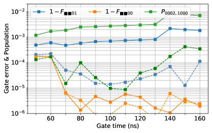
We end this section by showing that without the consideration of qubit decoherence, there could exist a performance trade-off between isolated two-qubit gate operations and simultaneous two-qubit gate operations, i.e., in general, isolated gate operations with slower gate-speed can suppress parasitic interactions within target qubit systems, but for simultaneous gate operations, fast-speed gates could mitigate parasitic interactions associated with nonparticipating spectator qubits. In Fig. 12, the solid line represents the isolated gate error with the other two nonparticipating qubits prepared in two different state-configurations, i.e., and , versus gate time in the four-qubit square system shown in Fig. 5(c). In general, we find that isolated gates with slow-speed have a lower error, but the increased gate error of with in the excited state and the leakage to state , i.e., , suggest that the gate error of simultaneous gate operations becomes serious.
To further elucidate the general physics behind the trade-off, we consider that the present four-qubit system can be simplified to a multi-anticrossing system that comprises a main avoided crossing with a dominated energy gap (at the working point) and several avoided crossings with tiny energy gaps (this is in general different from the parasitic interaction within target qubit systems, in which the strength of the parasitic interactions is comparable to or even larger than that of the desired interaction, thereby, the working point is chosen so that it is far detuned from the parasitic resonance points). The main avoided crossing results from the desired interaction used for realizing gate operations, e.g., the interaction between and , and the tiny avoided crossing comes from high-order parasitic interaction, e.g., interaction between and , and interactions between next-nearest-neighbor qubits, as shown in Fig. 11. In Fig. 13, we show two different situations that correspond to the two error sources discussed in Sec. III.2.2:
(i) as shown in Fig. 13(a), there is a tiny avoided crossing resulting from the interaction between and . Generally, to implement a gate operation, one needs to bias the system to the working point. Therefore, during the operation, the system will sweep through this tiny avoided crossing and then come back. Thus, sweeping through this avoided crossing with fast-speed could suppress leakage to state .
(ii) as shown in Fig. 13(b), around the working point, a tiny avoided crossing, i.e., labeled as , exists, corresponding to the parasitic interaction point (resulting from the coupling between and ). During the gate operation, the system approaches the parasitic resonance point, thus the detuning between and is reduced. In addition, the energy level is pushed down due to its coupling to the state , thereby, further reducing its detuning from . Ideally, the system dynamics should be restricted in the subspace spanned by . However, the off-resonance interaction between the and can result in an incomplete population swap between the two states, especially, when the detuning between and becomes smaller, a population swap with a larger magnitude will present, thus potentially causing non-negligible control or leakage error (here, i.e, leakage to the state ). Note that the same as the off-resonance error in single-qubit systems Malekakhlagh2021 , in general, the off-resonance swap can be suppressed by increasing the detuning between the two states, as demonstrated in Sec. III.2.2. Furthermore, the exact off-resonance swap error should be studied by considering the shape and the gate-time of the control pulse Sung2021 ; Foxen2020 ; Malekakhlagh2021 . In general, pulses with a long ramp can mitigate the off-resonance swap error. Moreover, the error itself exhibits a periodic dependence on the gate time, and the period generally is inversely proportional to the detuning. As shown in Fig. 12, the dashed line denotes the isolated gate error versus gate time with an increased qubit anharmonicity , giving a larger detuning between state and state (Fig. 9(b), about ). Compared to the case of (see Fig. 13, solid lines), we can find that due to the increased detuning, both the magnitude of leakage to state and the time of the oscillation period are decreased as expected. Thus, to mitigate the off-resonance error, particular attention should be paid to the parasitic resonance point (where a tiny avoided crossing exists) with a small detuning to the working point. In this case, the smaller the detuning, the longer the period of the error oscillation, thereby, implementing a gate operation within a short time can mitigate the off-resonance swap error (see Fig. 12, solid lines).
To circumvent the detrimental effect from these tiny-gap avoided crossings, on the whole, we argue that implementing short gates or pushing away these avoided-crossings could greatly relieve the population leakage and swap process involving parasitic next-nearest-neighbor interactions. However, fast-speed gate operations are commonly realized with potentially increased gate error within target qubit systems, such as the leakage error Foxen2020 . In the present qubit architecture, to suppress diabatic transitions within the target two-qubit system, the gate-length cannot be reduced below 50 ns, limited by the small qubit-bus coupling. This could raise a tread-off between gate error resulting from target qubit systems themselves and error from non-participating spectator qubits, as shown in Fig. 12. With regard to engineering quantum systems to remove harmful tiny-gap avoided crossings, although its success has been demonstrated in the four-qubit square system (see Sec. III.2.2), it is still an open question as to whether this will prove useful in a large qubit lattice.
IV conclusion and discussion
In this work, we first propose a qubit architecture with tunable coupling, where fixed-frequency transmon qubits are coupled via a tunable bus, and sub-100-ns CZ gates can be realized by applying a fast-adiabatic flux-pulse to the bus. Then, we thoroughly analyze the quantum crosstalk impact on simultaneous gate operations in this qubit architecture. In general, we find that characterization of isolated gate errors, especially, with all non-participating spectator qubits in their ground states, cannot capture the full physical picture of error sources behind simultaneous gate operations. Given this insight, we examine the isolated gate performance with non-participating spectator qubits in various state configurations. Combing with an inspection of the system dynamics during gate operations, we find that to ensure high simultaneous single-qubit gate fidelities, dressing-induced cross-driving should be seriously considered when one operates qubits near the frequency collision regions. For simultaneous two-qubit gates, while parasitic nearest-neighbor interactions are commonly suppressed, parasitic next-nearest-neighbor interactions involving spectator qubit can still exist, causing considerable leakage or control error when qubit systems sweep through or approach these parasitic resonance points slowly. As gate operations with slower speed can, in general, suppress unwanted interactions within target qubit systems, but for high-order parasitic interactions involving spectator qubits, one tends to favor short gates. This could give rise to a trade-off between the error resulting from target qubit systems themselves and the error from non-participating spectator qubits. Thus, our analysis suggests that in pursuit of a functional quantum processor, the qubit architecture should be examined carefully in the context of high-fidelity simultaneous gate operations.
To mitigate the dominated high-order parasitic interaction in the proposed qubit architecture, we also consider a hardware approach to mitigating their detrimental effect. We demonstrate that by engineering qubit parameters, we can push these parasitic resonance points far away from the working point of desired interaction. In this way, on average, there is almost an order of magnitude improvement in gate performance, giving the added error for simultaneous CZ gates below . The remaining error could be further suppressed by increasing the detuning between next-nearest-neighbor qubits. This suggests that the proposed qubit architecture may be a potential architecture towards a large-scale superconducting quantum processor with low quantum crosstalk.
Although our present analysis of quantum crosstalk focuses on superconducting qubit architecture with tunable buses, we expect that many of our conclusions may also be applied to other qubit architecture, such as the qubit architecture with tunable coupler Yan2018 ; Collodo2020 ; Xu2020 ; Foxen2020 ; Sete2021 , and or at the very least, may give some physical insight into the exact nature of quantum crosstalk in these qubit architectures. Meanwhile, the analysis procedure may also provide a preliminary guideline for analyzing quantum crosstalk in other qubit architecture, and may help motivate future work on bridging the gap between high-level, hardware-agnostic crosstalk characterization Sarovar2020 and the exact nature of crosstalk.
Acknowledgements.
We would like to thank Yanwu Gu, Mengjun Hu, Yingshan Zhang, Jingning Zhang, and Teng Ma for many helpful discussions. We also thank Yu Song and Shuang Yang for helpful suggestions on the manuscript. This work was supported by the Beijing Natural Science Foundation (Grant No.Z190012), the National Natural Science Foundation of China (Grants No.11890704, No.12004042, No.11905100), the National Key Research and Development Program of China (Grant No.2016YFA0301800), and the Key-Area Research and Development Program of Guang Dong Province (Grant No. 2018B030326001). P.X. was supported by the Young Fund of Jiangsu Natural Science Foundation of China (Grant No.BK20180750) and the National Natural Science Foundation of China (Grant No.12105146).Appendix A calibration procedure of gate operations
In this Appendix, we gave further detailed descriptions on the calibration procedure of gate operations (i.e., single-qubit X gate and two-qubit CZ gate) discussed in the main text. Here, for illustration purposes only, we consider the two-qubit system shown in Fig. 1. In the following discussion, we show how the single-qubit X gate and the two-qubit CZ gate are calibrated in the two-qubit system. As in Fig. 1, the system parameters are: qubit frequency , anharmonicity , and qubit-bus coupling (at . In addition, the idle point of the tunable bus is at , as marked by the black arrow in Fig. 1(c). In the following discussion, notations represent the full system states, and when confined to the qubit subspace, notation is used.
In addition, we note that the following introduced calibration procedures are also applied to the calibration of single-qubit gates and two-qubit gates in the four-qubit system studied in Sec. III.
A.1 Calibration of single-qubit X gates
As we mentioned in Sec. II.2.1, in the present work, the single-qubit X gate is implemented by using the DRAG scheme Motzoi2009 ; Chen2016 ; McKay2017 . For illustration purposes, here, we consider the implementation of a single-qubit X gate applied to the qubit . As shown in Eq. 4, the driven Hamiltonian for implementing is
| (9) |
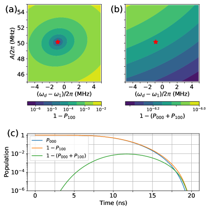
The gate is tuned up by adjusting the driving amplitude and the driving detuning of the pulse from the qubit bare frequency for a fixed gate length () and the parameter . Figure 14(a) shows the population error ( denotes the population in state at the end of the gate operation) as a function of the driving amplitude and the driving detuning for the two-qubit system initialized in state . In Fig. 14(b), we also show the leakage error . One can find that at the minimal error point, i.e., , marked by the red stars in Figs. 14(a) and (b), both the population error and leakage is suppressed below , as shown in Fig. 14(c). Note here that in the present setting, as expected, the obtained optimal driving frequency is indeed at the dressed qubit frequency of .
After obtaining the optimal parameter set from the result shown in Fig. 14, we characterize the fidelity of gate by using the metric given in Eq. 7, i.e.,
| (10) |
where denote the actual implemented X gate operation, and
| (11) |
According to the two-qubit system Hamiltonian given in Eq. 1 and the driven Hamiltonian given in Eq. LABEL:eq9, the actual evolution operator is
| (12) |
where , and denotes the time-ordering operator. Thus, in the single-qubit computational subspace for , the actual implemented X gate operation is given as
| (13) |
where is the projected operator defined in the computational subspace of the full system, i.e., the subspace spanned by . Finally, to account for the local single-qubit phase Chen2016 ; McKay2017 , the gate fidelity is obtained as Zhao2020b ; Zhao2020
| (14) |
with , where Z represents the single-qubit Pauli operator .
A.2 Calibration of CZ gates
As mentioned in Sec. II.2.2 and Sec. III.2, the CZ gate
| (15) |
is realized by applying a fixed-length () flux pulse to the tunable bus, tuning its frequency from its idle point () to the working point () and then coming back. The pulse shape is given in Eq. 8 with three Fourier coefficients , where . Thus, this gives rise to totally three free parameters . For reaching a target error at around , the free parameter set is determined by optimizing the CZ gate fidelity according to the metric given in Eq. 7, i.e.,
| (16) |
Similar to the case of single-qubit gates, according to the system Hamiltonian given in Eq. 1 and the pulse shape given in Eq. 8, the actual evolution operator for the gate operation is
| (17) |
Thus, truanted to the two-qubit computational subspace, the actual implemented CZ gate operation is given as
| (18) |
where is the projected operator defined in the two-qubit subspace spanned by . Finally, to account for the local single-qubit phases Zhao2020b ; Zhao2020 , the gate fidelity is obtained as
| (19) |
with , where Z and I represent the single-qubit Pauli operator and identity operators, and the order indexes the qubit number.
Appendix B population swap between next-nearest-neighboring qubits
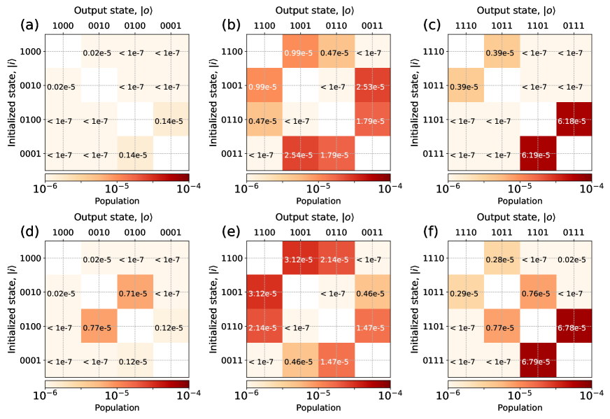
As shown in Fig. 11 and mentioned in Sec. II.2.2, the population swap between next-nearest-neighbor qubit pairs which results from off-resonance interaction among them in the four-qubit system, can contribute to the gate error of simultaneous CZ gates. Figure 15 shows the population swap matrix in the single-excitation subspace , the two-excitation subspace , and the three-excitation subspace of the four-qubit square system shown in Fig. 5(c). Each matrix element denotes the population in state after the gate operation with the qubit system initialized in state .
From Fig. 15, one can find that a significant population swap only exists for the state transition process involving next-nearest-neighboring qubits. These transitions are indicated by double-headed arrows connecting the states of next-nearest-neighboring qubits, as shown in Fig. 11. Moreover, as these population swaps are enabled by high-order processes, the population swap errors are suppressed below .
References
- (1) J. M. Martinis, Qubit Metrology for Building a Fault Tolerant Quantum Computer, npj Quantum Inf. 1, 15005 (2015).
- (2) M. Kjaergaard, M. E. Schwartz, J. Braumüller, P. Krantz, J. I.-J. Wang, S. Gustavsson, and W. D. Oliver, Superconducting qubits: Current state of play, Annu. Rev. Condens. Matter Phys. 11, 369 (2020).
- (3) Z. Chen, J. Kelly, C. Quintana, R. Barends, B. Campbell, Y. Chen, B. Chiaro, A. Dunsworth, A. G. Fowler, E. Lucero, E. Jeffrey, A. Megrant, J. Mutus, M. Neeley, C. Neill, P. J. J. ÓMalley, P. Roushan, D. Sank, A. Vainsencher, J. Wenner, T. C. White, A. N. Korotkov, and J. M. Martinis, Measuring and Suppressing Quantum State Leakage in a Superconducting Qubit, Phys. Rev. Lett. 116, 020501 (2016).
- (4) D. C. McKay, C. J. Wood, S. Sheldon, J. M. Chow, and J. M. Gambetta, Efficient z gates for quantum computing, Phys. Rev. A 96, 022330 (2017).
- (5) A. Somoroff, Q. Ficheux, R. A. Mencia, H. Xiong, R. V. Kuzmin, and V. E. Manucharyan, Millisecond coherence in a superconducting qubit, arXiv:2103.08578.
- (6) R. Barends, C. M. Quintana, A. G. Petukhov, Y. Chen, D. Kafri, K. Kechedzhi et al., Diabatic Gates for Frequency-Tunable Superconducting Qubits, Phys. Rev. Lett. 123, 210501 (2019).
- (7) M. A. Rol, F. Battistel, F. K. Malinowski, C. C. Bultink, B. M. Tarasinski, R. Vollmer, N. Haider, N. Muthusubramanian, A. Bruno, B. M. Terhal, and L. DiCarlo, Fast, High-Fidelity Conditional-Phase Gate Exploiting Leakage Interference in Weakly Anharmonic Superconducting Qubits, Phys. Rev. Lett. 123, 120502 (2019).
- (8) Y. Sung, L. Ding, J. Braumüller, A. Vepsäläinen, B. Kannan, M. Kjaergaard, A. Greene, G. O. Samach, C. McNally, D. Kim, A. Melville, B. M. Niedzielski, M. E. Schwartz, J. L. Yoder, T. P. Orlando, S. Gustavsson, and W. D. Oliver, Realization of High-Fidelity CZ and ZZ-Free iSWAP Gates with a Tunable Coupler, Phys. Rev. X 11, 021058 (2021).
- (9) Y. Xu, J. Chu, J. Yuan, J. Qiu, Y. Zhou, L. Zhang, X. Tan, Y. Yu, S. Liu, J. Li, F. Yan, and D. Yu, High-Fidelity, High-Scalability Two-Qubit Gate Scheme for Superconducting Qubits, Phys. Rev. Lett. 125, 240503 (2020).
- (10) B. K. Mitchell, R. K. Naik, A. Morvan, A. Hashim, J. M. Kreikebaum, B. Marinelli, W. Lavrijsen, K. Nowrouzi, D. I. Santiago, and I. Siddiqi, Hardware-Efficient Microwave-Activated Tunable Coupling Between Superconducting Qubits, arXiv:2105.05384.
- (11) K. X. Wei, E. Magesan, I. Lauer, S. Srinivasan, D. F. Bogorin, S. Carnevale, G. A. Keefe, Y. Kim, D. Klaus, W. Landers, N. Sundaresan, C. Wang, E. J. Zhang, M. Steffen, O. E. Dial, D. C. McKay, and A. Kandala, Quantum crosstalk cancellation for fast entangling gates and improved multi-qubit performance, arXiv:2106.00675.
- (12) E. A. Sete, N. Didier, A. Q. Chen, S. Kulshreshtha, R. Manenti, and S. Poletto, Parametric-Resonance Entangling Gates with a Tunable Coupler, Phys. Rev. Applied 16, 024050 (2021).
- (13) Q. Ficheux, L. B. Nguyen, A. Somoroff, H. Xiong, Ko. N. Nesterov, M. G. Vavilov, and V. E. Manucharyan, Realization of Fast Logic with Slow Qubits: Microwave-Activated Controlled-Z Gate on Low-Frequency Fluxoniums, Phys. Rev. X 11, 021026 (2021).
- (14) J. M. Chow, S. J. Srinivasan, E. Magesan, A. D. Córcoles, D. W. Abraham, J. M. Gambetta, and M. Steffen, Characterizing a four-qubit planar lattice for arbitrary error detection, Proc. SPIE 9500, Quantum Inf. Comput. 13, 95001G (2015).
- (15) F. Arute, K. Arya, R. Babbush, D. Bacon, J. C. Bardin, R. Barends, R. Biswas, S. Boixo, F. G. Brandao, D. A. Buell et al., Quantum supremacy using a programmable superconducting processor, Nature 574, 505 (2019).
- (16) Q. Zhu, S. Cao, F. Chen, M.-C. Chen, X. Chen, T.-H. Chung, H. Deng, Y. Du, D. Fan, M. Gong et al., Quantum Computational Advantage via 60-Qubit 24-Cycle Random Circuit Sampling, arXiv:2109.03494.
- (17) X. Zhang, W. Jiang, J. Deng, K. Wang, J. Chen, P. Zhang, W. Ren, H. Dong, S. Xu, Y. Gao, F. Jin, X. Zhu, Q. Guo, H. Li, C. Song, Z. Wang, D.-L. Deng, and H. Wang, Observation of a symmetry-protected topological time crystal with superconducting qubits, arXiv:2109.05577.
- (18) D. M. Zajac, J. Stehlik, D. L. Underwood, T. Phung, J. Blair, S. Carnevale, D. Klaus, G. A. Keefe, A. Carniol, M. Kumph, M. Steffen, O. E. Dial, Spectator Errors in Tunable Coupling Architectures, arXiv:2108.11221.
- (19) M. Sarovar, T. Proctor, K. Rudinger, K. Young, E. Nielsen, and R. Blume-Kohout, Detecting crosstalk errors in quantum information processors, Quantum 4, 321 (2020).
- (20) A. G. Fowler, M. Mariantoni, J. M. Martinis, and A. N. Cleland, Surface codes: Towards practical large-scale quantum computation, Phys. Rev. A 86, 032324 (2012).
- (21) J. M. Gambetta, A. D. Córcoles, S. T. Merkel, B. R. Johnson, John A. Smolin, J. M. Chow, C. A. Ryan, C. Rigetti, S. Poletto, T. A. Ohki, M. B. Ketchen, and M. Steffen, Characterization of Addressability by Simultaneous Randomized Benchmarking , Phys. Rev. Lett. 109, 240504 (2012).
- (22) K. Rudinger, T. Proctor, D. Langharst, M. Sarovar, K. Young, and R. Blume-Kohout, Probing Context-Dependent Errors in Quantum Processors, Phys. Rev. X 9, 021045 (2019).
- (23) C. Huang, X. Ni, F. Zhang, M. Newman, D. Ding, X. Gao, T. Wang, H. Zhao, F. Wu, G. Zhang, C. Deng, H. Ku, J. Chen, and Y. Shi, Alibaba Cloud Quantum Development Platform: Surface Code Simulations with Crosstalk, arXiv:2002.08918.
- (24) S. Niu and A. Todri-Sanial, Analyzing crosstalk error in the NISQ era, arXiv:2106.01671.
- (25) A. Ash-Saki, M. Alam, and S. Ghosh, Experimental Characterization, Modeling, and Analysis of Crosstalk in a Quantum Computer, IEEE Transactions on Quantum Engineering 1, 1 (2021).
- (26) K. Rudinger, C. W. Hogle, R. K. Naik, A. Hashim, D. Lobser, D. I. Santiago, M. D. Grace, E. Nielsen, T. Proctor, S. Seritan, S. M. Clark, R. Blume-Kohout, I. Siddiqi, and K. C. Young, Experimental Characterization of Crosstalk Errors with Simultaneous Gate Set Tomography, arXiv:2103.09890.
- (27) R. Barends, J. Kelly, A. Megrant, A. Veitia, D. Sank, E. Jeffrey, T. C. White, J. Mutus, A. G. Fowler, B. Campbell, Y. Chen, Z. Chen, B. Chiaro, A. Dunsworth, C. Neill, P. O’Malley, P. Roushan, A. Vainsencher, J. Wenner, A. N. Korotkov, A. N. Cleland, and J. M. Martinis, Superconducting quantum circuits at the surface code threshold for fault tolerance, Nature 508, 500 (2014).
- (28) D. M. Abrams, N. Didier, S. A. Caldwell, B. R. Johnson, and C. A. Ryan, Methods for Measuring Magnetic Flux Crosstalk between Tunable Transmons, Phys. Rev. Applied 12, 064022 (2019).
- (29) X. Dai, D. M. Tennant, R. Trappen, A. J. Martinez, D. Melanson, M. A. Yurtalan, Y. Tang, S. Novikov, J. A. Grover, S. M. Disseler, J. I. Basham, R. Das, D. K. Kim, A. J. Melville, B. M. Niedzielski, S. J. Weber, J. L. Yoder, D. A. Lidar, and A. Lupascu, Calibration of flux crosstalk in large-scale flux-tunable superconducting quantum circuits, arXiv:2105.14360.
- (30) M. Takita, A. D. Córcoles, E. Magesan, B. Abdo, M. Brink, A. Cross, J. M. Chow, and J. M. Gambetta, Demonstration of Weight-Four Parity Measurements in the Surface Code Architecture, Phys. Rev. Lett. 117, 210505 (2016).
- (31) M. Takita, A. W. Cross, A. D. Córcoles, J. M. Chow, and J. M. Gambetta, Experimental Demonstration of Fault-tolerant State Preparation with Superconducting Qubits, Phys. Rev. Lett. 119, 180501 (2017).
- (32) D. C. McKay, S. Sheldon, J. A. Smolin, J. M. Chow, and J. M. Gambetta, Three Qubit Randomized Benchmarking, Phys. Rev. Lett. 122, 200502 (2019).
- (33) N. Sundaresan, I. Lauer, E. Pritchett, E. Magesan, P. Jurcevic, and J. M. Gambetta, Reducing Unitary and Spectator Errors in Cross Resonance with Optimized Rotary Echoes, PRX Quantum 1, 020318 (2020).
- (34) A. Winick, J. J. Wallman, and J. Emerson, Simulating and Mitigating Crosstalk, Phys. Rev. Lett. 126, 230502 (2021).
- (35) X. Deng, Y. Hai, J. Li, and Y. Song, Correcting correlated errors for quantum gates in multi-qubit systems using smooth pulse control, arXiv:2103.08169.
- (36) V. Tripathi, H. Chen, M. Khezri, K. Yip, E. M. Levenson-Falk, and D. A. Lidar, Suppression of crosstalk in superconducting qubits using dynamical decoupling, arXiv:2108.04530.
- (37) P. Murali, D. C. McKay, M. Martonosi, and A. Javadi-Abhari, Software Mitigation of Crosstalk on Noisy Intermediate-Scale Quantum Computers, arXiv:2001.02826 .
- (38) Y. Ding, P. Gokhale, S. F. Lin, R. Rines, T. Propson, and F. T. Chong, Systematic Crosstalk Mitigation for Superconducting Qubits via Frequency-Aware Compilation, arXiv:2008.09503.
- (39) K. N. Smith, G. S. Ravi, P. Murali, J. M. Baker, N. Earnest, A. Javadi-Abhari, and F. T. Chong, Error Mitigation in Quantum Computers through Instruction Scheduling, arXiv:2105.01760.
- (40) Y. Chen, C. Neill, P. Roushan, N. Leung, M. Fang, R. Barends, J. Kelly, B. Campbell, Z. Chen, B. Chiaro, A. Dunsworth, E. Jeffrey, A. Megrant, J. Y. Mutus, P. J. J. O’Malley, C. M. Quintana, D. Sank, A. Vainsencher, J. Wenner, T. C. White, M. R. Geller, A. N. Cleland, and J. M. Martinis, Qubit architecture with high coherence and fast tunable coupling, Phys. Rev. Lett. 113, 220502 (2014).
- (41) F. Yan, P. Krantz, Y. Sung, M. Kjaergaard, D. L. Campbell, T. P. Orlando, S. Gustavsson, and W. D. Oliver, Tunable Coupling Scheme for Implementing High-Fidelity Two-Qubit Gates, Phys. Rev. Applied 10, 054062 (2018).
- (42) A.D. Patterson, J. Rahamim, T. Tsunoda, P.A. Spring, S. Jebari, K. Ratter, M. Mergenthaler, G. Tancredi, B. Vlastakis, M. Esposito, and P.J. Leek, Calibration of a Cross-Resonance Two-Qubit Gate Between Directly Coupled Transmons, Phys. Rev. Applied 12, 064013 (2019).
- (43) P. Zhao, P. Xu, D. Lan, X. Tan, H. Yu, and Y. Yu, Switchable Next-Nearest-Neighbor Coupling for Controlled Two-Qubit Operations, Phys. Rev. Applied 14, 064016 (2020).
- (44) P. S. Mundada, G. Zhang, T. Hazard, and A. A. Houck, Suppression of Qubit Crosstalk in a Tunable Coupling Superconducting Circuit, Phys. Rev. Applied 12, 054023 (2019).
- (45) J. Ku, X. Xu, M. Brink, D. C. McKay, J. B. Hertzberg, M. H. Ansari, and B. L. T. Plourde, Suppression of Unwanted ZZ Interactions in a Hybrid Two-Qubit System, Phys. Rev. Lett. 125, 200504 (2020).
- (46) P. Zhao, P. Xu, D. Lan, J. Chu, X. Tan, H. Yu, and Y. Yu, High-Contrast ZZ Interaction Using Superconducting Qubits with Opposite-Sign Anharmonicity, Phys. Rev. Lett. 125, 200503 (2020).
- (47) X. Xu and M.H. Ansari, ZZ freedom in two qubit gates, Phys. Rev. Applied 15, 064074 (2021).
- (48) A. Kandala, K. X. Wei, S. Srinivasan, E. Magesan, S. Carnevale, G. A. Keefe, D. Klaus, O. Dial, and D. C. McKay, Demonstration of a High-Fidelity CNOT for Fixed-Frequency Transmons with Engineered ZZ Suppression, arXiv:2011.07050.
- (49) P. Zhao, D. Lan, P. Xu, G. Xue, M. Blank, X. Tan, H. Yu, and Y. Yu, Suppression of Static ZZ Interaction in an All-Transmon Quantum Processor, Phys. Rev. Applied 16, 024037 (2021).
- (50) A. D. K. Finck, S. Carnevale, D. Klaus, C. Scerbo, J. Blair, T. G. McConkey, C. Kurter, A. Carniol, G. Keefe, M. Kumph, and O.E. Dial, Suppressed crosstalk between two-junction superconducting qubits with mode-selective exchange coupling, arXiv:2105.11495.
- (51) A. Noguchi, A. Osada, S. Masuda, S. Kono, K. Heya, S. P. Wolski, H. Takahashi, T. Sugiyama, D. Lachance-Quirion, and Y. Nakamura, Fast parametric two-qubit gates with suppressed residual interaction using the second-order nonlinearity of a cubic transmon, Phys. Rev. A 102, 062408 (2020).
- (52) A. Petrescu, C. L. Calonnec, C.Leroux, A. D. Paolo, P. Mundada, S. Sussman, A. Vrajitoarea, A. A. Houck, and A. Blais, Accurate methods for the analysis of strong-drive effects in parametric gates, arXiv:2107.02343.
- (53) C. Leroux, A. D. Paolo, and A. Blais, Superconducting coupler with exponentially large on-off ratio, arXiv:2107.09861.
- (54) X. Li, T. Cai, H. Yan, Z. Wang, X. Pan, Y. Ma, W. Cai, J. Han, Z. Hua, X. Han, Y. Wu, H. Zhang, H. Wang, Yipu Song, Luming Duan, and Luyan Sun, Tunable Coupler for Realizing a Controlled-Phase Gate with Dynamically Decoupled Regime in a Superconducting Circuit, Phys. Rev. Applied 14, 024070 (2020).
- (55) S. Krinner, S. Lazar, A. Remm, C.K. Andersen, N. Lacroix, G.J. Norris, C. Hellings, M. Gabureac, C. Eichler, and A. Wallraff, Benchmarking Coherent Errors in Controlled-Phase Gates due to Spectator Qubits, Phys. Rev. Applied 14, 024042 (2020).
- (56) M. Malekakhlagh, E. Magesan, and D. C. McKay, First-principles analysis of cross-resonance gate operation, Phys. Rev. A 102, 042605 (2020).
- (57) T.-Q. Cai, X.-Y. Han, Y.-K. Wu, Y.-L. Ma, J.-H. Wang, Z.-L. Wang, H.-Y Zhang, H.-Y Wang, Y.-P. Song, and L.-M. Duan, Impact of Spectators on a Two-Qubit Gate in a Tunable Coupling Superconducting Circuit, Phys. Rev. Lett. 127, 060505 (2021).
- (58) J. Chu and F. Yan, Coupler-Assisted Controlled-Phase Gate with Enhanced Adiabaticity, arXiv:2106.00725.
- (59) J. Koch, T. M. Yu, J. Gambetta, A. A. Houck, D. I. Schuster, J. Majer, A. Blais, M. H. Devoret, S. M. Girvin, and R. J. Schoelkopf, Charge-insensitive qubit design derived from the cooper pair box, Phys. Rev. A 76, 042319 (2007).
- (60) D. C. McKay, S. Filipp, A. Mezzacapo, E. Magesan, J. M. Chow, and J. M. Gambetta, Universal gate for fixed-frequency qubits via a tunable bus, Phys. Rev. Applied 6, 064007 (2016).
- (61) R. Krishnan and J. A. Pople, Approximate fourth-order perturbation theory of the electron correlation energy, Int. J. Quantum Chem. 14, 91 (1978).
- (62) L. DiCarlo, J. M. Chow, J. M. Gambetta, L. S. Bishop, B. R. Johnson, D. I. Schuster, J. Majer, A. Blais, L. Frunzio, S. M. Girvin, and R. J. Schoelkopf, Demonstration of two-qubit algorithms with a superconducting quantum processor, Nature (London) 460, 240 (2009).
- (63) L. Jin, Implementing High-fidelity Two-Qubit Gates in Superconducting Coupler Architecture with Novel Parameter Regions, arXiv:2105.13306.
- (64) M. H. Goerz, F. Motzoi, K. B. Whaley, and C. P. Koch, Charting the circuit QED design landscape using optimal control theory, npj Quantum Information 3, 37 (2017).
- (65) G. S. Paraoanu, Microwave-induced coupling of superconducting qubits , Phys. Rev. B 74, 140504(R) (2006).
- (66) C. Rigetti and M. Devoret, Fully microwave-tunable universal gates in superconducting qubits with linear couplings and fixed transition frequencies, Phys. Rev. B 81, 134507 (2010).
- (67) E. Magesan and J. M. Gambetta, Effective Hamiltonian models of the cross-resonance gate, Phys. Rev. A 101, 052308 (2020).
- (68) M. Brink, J. M. Chow, J. Hertzberg, E. Magesan, and Sami Rosenblatt, Device challenges for near term superconducting quantum processors: frequency collisions, 2018 IEEE International Electron Devices Meeting (IEDM), (2018).
- (69) J. Kelly, R. Barends, B. Campbell, Y. Chen, Z. Chen, B. Chiaro, A. Dunsworth, A. G. Fowler, I.-C. Hoi, E. Jeffrey, A. Megrant, J. Mutus, C. Neill, P. J. J. ÓMalley, C. Quintana, P. Roushan, D. Sank, A. Vainsencher, J. Wenner, T. C. White, A. N. Cleland, and J. M. Martinis, Optimal Quantum Control Using Randomized Benchmarking, Phys. Rev. Lett. 112, 240504 (2014).
- (70) M. Malekakhlagh and E. Magesan, Mitigating off-resonant error in the cross-resonance gate, arXiv:2108.03223.
- (71) F. Motzoi, J. M. Gambetta, P. Rebentrost, and F. K. Wilhelm, Simple Pulses for Elimination of Leakage in Weakly Nonlinear Qubits, Phys. Rev. Lett. 103, 110501 (2009).
- (72) L. H. Pedersen, N. M. Møller, and K. Mølmer, Fidelity of quantum operations, Phys. Lett. A 367, 47 (2007).
- (73) C. J. Wood and J. M. Gambetta, Quantification and characterization of leakage errors, Phys. Rev. A 97, 032306 (2018).
- (74) S. Huang, B. Lienhard, G. Calusine, A. Vepsäläinen, J. Braumüller, D. K. Kim, A. J. Melville, B. M. Niedzielski, J. L. Yoder, B. Kannan, T. P. Orlando, S. Gustavsson, and W. D. Oliver, Microwave Package Design for Superconducting Quantum Processors, PRX Quantum 2, 020306 (2021).
- (75) K. Linghu et al., in preparation. (2020).
- (76) J. M. Martinis and M. R. Geller, Fast adiabatic qubit gates using only control, Phys. Rev. A 90, 022307 (2014).
- (77) M. C. Collodo, J. Herrmann, N. Lacroix, C. K. Andersen, A. Remm, S. Lazar, J. Besse, T. Walter, A. Wallraff, and C. Eichler, Implementation of Conditional Phase Gates Based on Tunable Interactions, Phys. Rev. Lett. 125, 240502 (2020).
- (78) J. Stehlik, D. M. Zajac, D.L. Underwood, T. Phung, J. Blair, S. Carnevale, D. Klaus, G. A. Keefe, A. Carniol, M. Kumph, M. Steffen, and O. E. Dial, Tunable Coupling Architecture for Fixed-Frequency Transmon Superconducting Qubits, Phys. Rev. Lett. 127, 080505 (2021).
- (79) J. M. Kreikebaum, K. P. O’Brien, A. Morvan, and I. Siddiqi, Improving wafer-scale Josephson junction resistance variation in superconducting quantum coherent circuits, Supercond. Sci. Technol. 33, 06LT02 (2020).
- (80) J. B. Hertzberg, E. J. Zhang, S. Rosenblatt, E. Magesan, J. A. Smolin, J.-B. Yau, V. P. Adiga, M. Sandberg, M. Brink, Je. M. Chow, and J. S. Orcutt, Laser-annealing Josephson junctions for yielding scaled-up superconducting quantum processors, npj Quantum Information 7, 129 (2021).
- (81) B. Foxen, C. Neill, A. Dunsworth, P. Roushan, B. Chiaro, A. Megrant, J. Kelly, Z. Chen, K. Satzinger, R. Barends et al., Demonstrating a Continuous Set of Two-Qubit Gates for Near-Term Quantum Algorithms, Phys. Rev. Lett. 125, 120504 (2020).
- (82) M. D. Hutchings, J. B. Hertzberg, Y. Liu, N. T. Bronn, G. A. Keefe, M. Brink, J. M. Chow, and B. L. T. Plourde, Tunable Superconducting Qubits with Flux-Independent Coherence, Phys. Rev. Applied 8, 044003 (2017).
- (83) P. J. Leek, S. Filipp, P. Maurer, M. Baur, R. Bianchetti, J. M. Fink, M. Göppl, L. Steffen, and A. Wallraff, Using sideband transitions for two-qubit operations in superconducting circuits, Phys. Rev. B 79, 180511(R) (2009).
- (84) S. A. Caldwell, N. Didier, C. A. Ryan, E. A. Sete, A. Hudson, P. Karalekas, R. Manenti, M. P. da Silva, R. Sinclair, E. Acala, et al., Parametrically Activated Entangling Gates Using Transmon Qubits, Phys. Rev. Applied 10, 034050 (2018).
- (85) M. Pechal, G. Salis, M. Ganzhorn, D. J. Egger, M. Werninghaus, and S. Filipp, Characterization and tomography of a hidden qubit, arXiv:2011.08987.
- (86) M. Jerger, A. Kulikov, Z. Vasselin, and A. Fedorov, In Situ Characterization of Qubit Control Lines: A Qubit as a Vector Network Analyzer, Phys. Rev. Lett. 123, 150501 (2019).
- (87) M. A. Rol, L. Ciorciaro, F. K. Malinowski, B. M. Tarasinski, R. E. Sagastizabal, C. C. Bultink, Y. Salathe, N. Haandbaek, J. Sedivy, and L. DiCarlo, Time-domain characterization and correction of on-chip distortion of control pulses in a quantum processor, Appl. Phys. Lett. 116, 054001 (2020).
- (88) B. Foxen, J. Y. Mutus, E. Lucero, E. Jeffrey, D. Sank, R. Barends, K. Arya, B. Burkett, Y. Chen, Z. Chen, B. Chiaro, A. Dunsworth, A. Fowler, C. Gidney, M. Giustina et al., High speed flux sampling for tunable superconducting qubits with an embedded cryogenic transducer, Supercond. Sci. Technol. 21, 015012 (2019).